GE Telaire Ventostat 8001 User manual

Telaire Ventostat®8000 Series CO2 Sensors
User Instructions
GE
Sensing
T62659-007
October 2006
Page 1 of 7
Introduction
The GE Telaire Ventostat®8001/
8002 carbon dioxide (CO2) sensors and
controllers are designed for Demand
Controlled Ventilation (DCV) in
buildings. This approach, using CO2as
an indicator of occupancy, allows
ventilation based on actual occupancy
while still maintaining ASHARE
recommended per-person ventilation
rates. Over ventilation of buildings can
be reduced, energy can be saved, and
quality can be optimized.
The optional black case (PN 8001B and
PN 8002B) is UL94-V5 rated, making
these models suitable for mounting
directly inside the ductwork. Typical
applications for Ventostat®8001/8002 series include office buildings,
conference rooms, schools, retail stores, restaurants, gymnasiums, and
movie theatres.
Installing the Sensor
NOTICE!
Use of cellular telephones or radio transceivers within two (2) feet of the
sensor during calibration process could cause sensor interference,
calibration errors and affect sensor accuracy. Please refrain from using
these devices during sensor calibration.
Install the mounting plate and sensor as follows:
1. Prepare for installation by using the mounting holes configured for
US or European junction boxes.
2. Use the mounting plate as a template to mark the mounting holes.
See Figure 1, View A below.
Figure 1: Ventostat®CO2Controller - Mounting
3. Secure the mounting plate to the wall or junction box and make
necessary wire connections.
4. Mount the controller on the base by aligning the top clips and then
securing to the bottom clips, as shown in Figure 1, View B above. A
“snap” sound will indicate that the sensor is secure. The sensor will
now have power. A 2 minute warm-up will take place. After 2
minutes, the sensor will stabilize and display the “Normal Mode”
(current CO2readings).
5. At this point one of nine preset programs or one custom channel can
be selected for operation. See the section “Configuring the Sensor”
on page 3.
6. Finish installation by sliding the cover over the menu keys and
secure with the supplied screw.
Mounting the Sensor into the Duct
The 8001B and 8002B have the UL94-V5 rated black case and are
specifically designed for mounting inside the return air ductwork. When
mounting these products inside the ductwork, seal the hole around the
wires and leave the duct insulation in place to prevent condensation
which may damage the sensor.
Pitot Tube Installation for the
8001 and 8002
Install the mounting bracket, then install the pitot tube assembly as
follows:
Note: The length of the Tygon®tubing is three feet. In order to
maintain optimum accuracy, the tubing should not be
lengthened. If the sensor is mounted closer than three
feet, the excess tubing should be shortened to avoid
interference with mechanical or moving devices.
1. To mount the pitot tube, drill one 7/8” hole through the duct as
shown in Figure 2 below.
Figure 2: Pitot Tube - Installation
View A View B View C
Mounting
Plate
Ventostat
CO2Sensor/
Controller
clear
mode
enter
Top Clips
Bottom Clips
H
FLOW
L
Filter mustbe
attached to the
“H” side ofthe
pitot tube
View in Direction of A
Drill One Hole
7/8” in Diameter
Drill Two Machine
Screw Holes
Mounting
Flange

Page 2 Telaire Ventostat™ 8000 Series
2. Insert the pitot tube and mark the two remaining holes for the
mounting screws.
3. Punch or drill the two marked holes.
4. Note the direction of airflow in the duct (see View in Direction of A)
above.
5. Note the marking on the pitot tube flange and insert the tube so that
it is properly aligned with the airflow.
6. To ensure an airtight seal, make sure the mounting surface of the
duct is clear of dirt or obstructions. Then, attach the pitot tube to the
duct with sheet metal screws or rivets.
7. On top of the sensor, unscrew the protective caps from the tube
connectors.
8. Check the length of the tubing before attaching to the sensor. The
tubing should connect without stretching or pulling. If the length is
long enough to create a loop or bind in the tubing, it should be
shortened.
9. To shorten the tubing, remove the connectors that attach to the
sensor and cut the tubing to the required length.
10. Replace the tubing connectors by using a twisting or screwing
motion.Verify the connection is secure.
Note: If the tubing length has been shortened, be sure the in-
line filter is replaced on the pitot tube connector marked
with an “H” as shown in Figure 2, View in Direction of
A (on the previous page).
11. Complete the installation by screwing the tube connectors to the
input ports on the sensor. The tubing connectors can be attached to
either input port. It will not affect the performance of the sensor.
Accessory Enclosures
Three kinds of accessory enclosures are listed below, and two are shown
in Figure 3 below.
• Model 1508 Duct Mount Enclosure (Aspiration Box) - Any 8000
product can be installed inside this enclosure.
• Model 1551 Outside Air Measurement Enclosure - This NEMA-
3R enclosure is weatherproof for measuring outside air CO2con-
centrations. It also includes heat stabilizers.
• Model 1505 Harsh Environment Enclosure - For extreme envi-
ronments where the sensor might be subjected to condensation or
water spray such as those found in greenhouses or breweries-
NEMA-3R rated.
Figure 3: Accessory Enclosures
Typical Wiring Diagrams
The typical wiring diagrams appear in Figure 4 through Figure 8
below.
Figure 4: AC Power 3/4 Wires System - Diagrams
Figure 5: Relay Contacts and Lennox L-Series
Diagrams
Figure 6: Lennox L-Series/Mounting Bracket Diagrams
Figure 7: Damper Actuator and W7459 Logic Module
Diagrams
Use Either Output
0-10Vout
4-20mAout
1
2
Input
L1
L2
18-30 VAC RMS
12
3
4
5
6
78
Ventostat®
MountingBracket
0-10Vout
4-20mAout
1
2
Input
L1
L2
18-30 VAC RMS
12
3
4
5
6
78
SignalGround
Ventostat®
MountingBracket
Isolated AC Power 4-Wire System
AC Power 3-Wire System
L1
L2
18-30 VAC RMS
NCNO
COM
Ventostat
®
MountingBracket
1
2
Input
12
3
4
5
6
7
8
Common
NCNO
COM
Ventostat MountingBracket
1
2
Input
12
3
4
5
6
7
8
Common
6
7
8
910 11 12 13 14
16
24VAC+
24VAC
GND
24VAC In
Common
+10VDCIn
15
TB1
Using the Relay Contacts Lennox L-Series
24VAC+
24VAC
GND
AI-3
AI-CM
TB1
1
2
3
4
5
6
7
8
1
2
Input
12
3
4
5
6
7
8
Common
Ventostat MountingBracket
Lennox L-Series w/Johnson Controls
Metasys UNT or Facilitator FA-UNT
8-Pin and 2-Pin Terminal
Ventostat®
MountingBracket
1
2
Input
12
3
4
5
6
78
0-10V Output
SignalGround
4-20mA Output
RelayNorm Closed
RelayCommon
RelayNorm Open
Not Used
Not Used
AC- /GND
AC+/DC+
Block Pin Designations on
the Ventostat Mounting Bracket
(P1)
(P)
Rear View
Front ViewPP1
Honeywell Damper
Actuator M7415 and
W7459LogicModule
(-)
(+)
Honeywell
Q769C 0-10 Vdc
Adaptor
Black
OptionalHigh
and/or Low
Temp Swtich
White
L1
L2
18-30 VAC RMS
1
2
Input
1
2
3
4
5
6
78
Common
Ventostat MountingBracket
Honeywell M7415 Damper Actuator with W7459 Logic Module

Telaire Ventostat™ 8000 Series Page 3
Set minimum position potentiometer to twice the design load. For
example, if the space is designed for 30 people at 15 cfm/person, adjust
the minimum position potentiometer at the economizer logic to 900 cfm.
This will allow the economizer to introduce 450 cfm (1000 ppm CO2
level) at the design load. The CO2sensor should use “STDSET#1.”
Note: For 24V, do not use a HVAC unit transformer. Provide
24 V by using a non-grounding transformer.
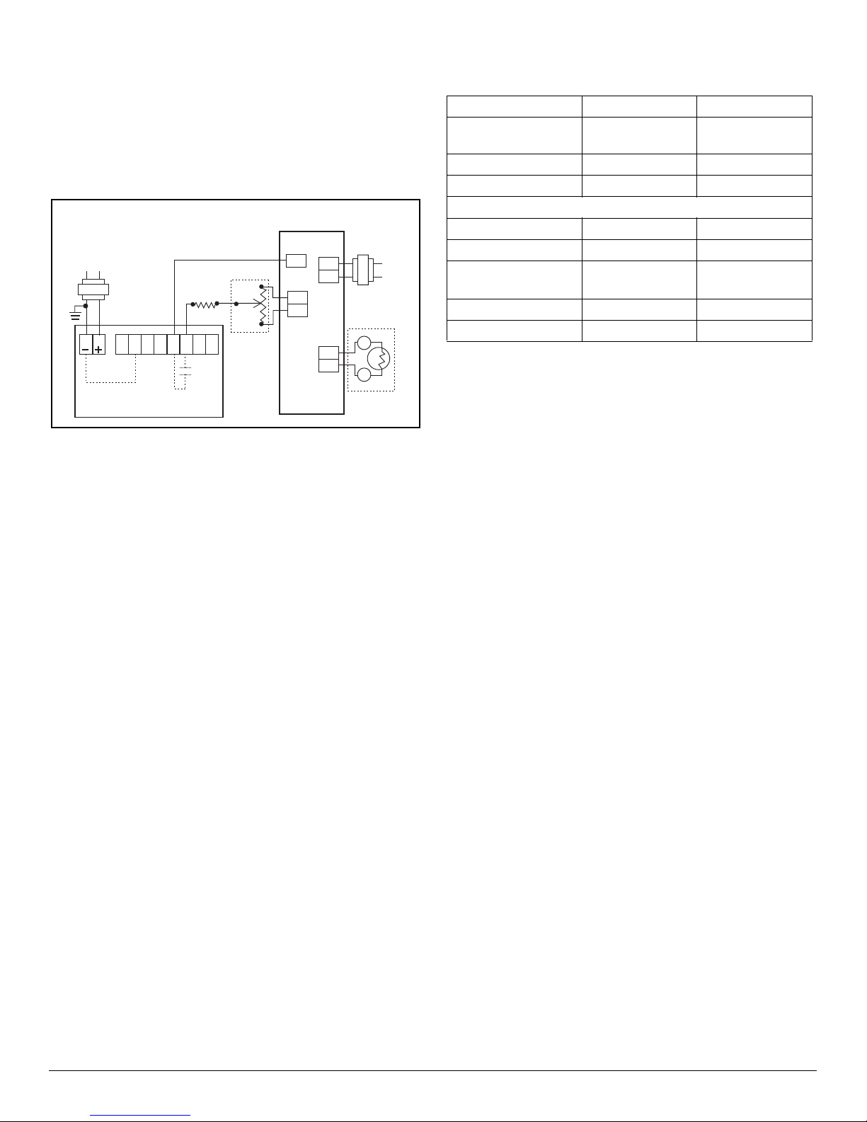
Figure 8: Economizer Actuator and Interface Board -
Diagrams
Configuring the Sensor
The sensor has two different settings:
•User Adjustable Sensor Settings
•Factory Settings
User Adjustable Sensor Settings
The GE Telaire 8000 series includes features which are user adjustable.
These adjustments can be made using the keypad on display units, or by
the PC based UIP program that communicates to the sensor via a custom
RS232 interface cable.
Factory Settings
The default settings are the typical settings used by a building control
system.
If the installation requires changes to the sensor, the user can customize
certain characteristics of the sensor. For example, non-factory settings
may be applicable when the sensor is being connected to equipment that
has a fixed input range (e.g., actuators used with economizer systems).
Sensor Programming Features
Outlined below in Table 1 are the adjustable parameters of the sensor
and the factory setting. In addition to offering these adjustable features,
the programming interface allows for a fast and simple adjustment of
sensor calibration.
All GE Telaire 8000 series products are calibrated at sea level. As
altitude increases, the accuracy of this sensor, as of all gas sensors,
introduces an error of approximately -3% of the reading per 1,000 ft of
elevation. Users that are in elevations significantly higher than sea level,
such as Denver, Colorado, should consider adjusting the altitude to have
the most accurate reading. The altitude setting can be adjusted on the
unit in 500 ft increments.
ABC Logic™ Self Calibration System
All GE Telaire 8000 series sensors are factory set with the ABC Logic
(Automatic Background Calibration) self calibration feature ON. This
feature allows the sensor to continually re-calibrate itself when the
indoor concentrations drop to outside levels while the building is
unoccupied. Generally a building must be regularly unoccupied for 4
hours or more for this self-calibration system to operate properly. Under
these conditions, the ABC Logic feature should maintain sensor
calibration over the lifetime of the sensor. The ABC Logic feature should
be turned OFF where a building is continuously occupied 24 hours per
day, or where there could be significant sources of non-occupant related
CO2such as greenhouses, breweries and other industrial and food
processing applications.
Pre-Programmed Settings
In addition to the factory setting for the 8000 series sensors, nine
standard settings can easily be selected using the keypad (display units
only) or the PC based UIP Program. Table 2 on the next page describes
each of the settings. The definitions for some of the terms used in the
table are described in more detail as part of the custom settings outline in
the “Custom Settings” section on the next page.
Settings 1, 2 and 3 are applicable for automated or computerized
building control systems.
Settings 4 to 7 are specifically designed for operation with economizer
controls and actuators where a 0-10 VDC signal will provide 0-100%
outside air modulation. These control settings provide different
modulation ranges, depending on the target cfm-per-person ventilation
rate desired. As described below, the exponential setting is best used in
applications that have large volumes of air and people, such as
auditoriums, gyms and large conference areas.
Setting 8 is for use in occupational health and safety applications where
users want to measure concentrations in relation to the 5000 ppm, 8 hour
exposure levels established by OSHA (Occupation Safety and Health
Administration).
M100E
8T2
T1
L1
L2
S2
S1
B
R
T
A91MixedAir
Thermistor
9
10
Open
Close
Y45AA-9Remote Minimum
Position Potentiometer
(1,000-10,000 ohm)
L1
L2
Common
1
2
Input
12
3
4
5
6
78
Common
Ventostat MountingBracket
Johnson Controls M100E Economizer Actuator with R81EAA-2
Interface Board
Table 1: 8000 Series Adjustment Parameters and
Factory Settings
Adjustment Range Factory Setting
Altitude Above Sea
Level
0 - 10,000 ft. 0 ft.
ABC Logic™ ON/OFF ON
Select Standard Setting 1 to 9 1
Customize Setting:
PPM Range 0 - 10,000 0-2,000
Output Range 4-20 mA/ 0 - 10 V 4 - 20 mA/ 0-10 V
Proportional/
Exponential Output
Select One Proportional
Relay Setpoint 0 - 10,000 PPM 1000 PPM
Relay Hysteresis 0 - 10,000 PPM 50 PPM

Page 4 Telaire Ventostat™ 8000 Series
Setting 9 is intended for use in parking garages where CO2can be used
as an indicator of the presence of combustion fumes. As part of most
types of combustion, CO2is generated at a rate that is 50 times or more
than other, more harmful contaminants. This is particularly the case with
the extensive use of catalytic converters that tend to remove
most of the carbon monoxide from vehicle exhaust. The 700
ppm setting should maintain levels of other exhaust
contaminants well below levels of concern.
Custom Settings
In addition to the nine standard settings programmed into the 8000 series
(see Table 2 above), users can also custom program the sensor for their
own application.
Outlined below is a brief description of each of the adjustable custom
settings:
Control Range - The range that will correspond to the analog signal
output range. The range consists of a low level and a high level in ppm.
Setting this range does not limit the actual measurement or display
range.
Analog Output Range - Can be expressed in V or mA. This range
will correspond to the range of CO2concentrations established in the
measurement range. The output in V or mA is selected based on the wir-
ing terminals. It is possible to simultaneously connect to both the V and
mA outputs.
Proportional or Exponential Control - Proportional (linear) control
increases the signal output in proportion to the increase in CO2concen-
trations for the measurement range and analog output range selected.
Exponential control provides an output function that is exponential over
the selected range of the sensor. The effect of the exponential output is to
initially introduce more ventilation to the space as concentrations are at
the lower level of the control range. The exponential output is particu-
larly useful for areas of potential high occupancy and high air volume
where significant time may be required for CO2levels to build up.
Potential applications include arenas, gyms, auditoriums and large con-
ference areas. Examples of both types of outputs appear in Figure 9 on
the next page.
Relay Set Point - Establishes the level at which the on-board relay
will activate. The relay is a double pole single throw (DPST) relay that
allows the user to operate the relay normally open or normally closed
based on the selection of wiring terminals connected on the sub-base.
Relay Hysteresis (Deadband) - Is the point at which the relay will
deactivate. It is entered as a ppm value below the setpoint. A sensor with
a relay setting of 1000 and a hysteresis of 50 would activate at 1000
ppm and deactivate at 950 ppm.
Table 2: Standard Settings Adjustable via Keypad UIP Interface
Setting
No.
Type of
Equipment
Type of
Output
Ventilation
Rate (cfm/
Person)
Analog
Output
CO2
Control
Range
(ppm)
Optional
Relay
Setpoint
(ppm)
Relay
Hysteresis
(ppm)
1 Interface w/Standard
Building Control
System
Proportional Any 0 - 10V
4 - 20 mA
0 - 2000 1000 50
2 Interface w/Standard
Building Control
System
Proportional Any 2 - 10V
7 - 20 mA
0 - 2000 1000 50
3 Interface w/Standard
Building Control
System
Exponential Any 0 - 10V
4 - 20 mA
0 - 2000 1100 50
4 Economizer (Hvac) Proportional 15 0 - 10V
4 - 20 mA
0 - 1100 1100 50
5 Economizer (Hvac) Proportional 20 0 - 10V
4 - 20 mA
0 - 900 900 50
6 Economizer (Hvac) Exponential 15 0 - 10V
4 - 20 mA
0 - 1100 1100 50
7 Economizer (Hvac) Exponential 20 0 - 10V
4 - 20 mA
0 - 900 900 50
8 Health & Safety Proportional NA 0 - 10V
4 - 20 mA
0 - 9999 5000 500
9 Parking/Air Intakes/
Loading Docks
Proportional NA 0 - 10V
4 - 20 mA
0 - 2000 700 50

Telaire Ventostat™ 8000 Series Page 5
Figure 9: Design Ventilation Rate
Adjusting Sensor Using Display
The four buttons listed below perform the following functions:
•[CLEAR]- Resets Menu / Returns to Normal Mode
•[MODE]- Toggles to Next Menu Item
•[ENTER] - Press to Lock Menu
•[UP/DOWN] - Increase/Decrease Selection Value
Altitude Correction and ABC Logic™ (ON/
OFF)
1. After 2 minute warm-up period, press [CLEAR] + [MODE]. Hold at
least 5 seconds until the sensor enters the edit mode.
2. The first menu is Altitude Correction. Use the [UP/DOWN] button
to adjust to the proper altitude in 500 ft. increments.
3. Press [ENTER] to lock in value, then press [ MODE] to proceed to
ABC Logic.
4. Use the [UP/DOWN] button to switch to ON or OFF.
5. Press [ENTER] to lock value then press [MODE] to proceed to
Normal Mode. It is recommended that the ABC Logic feature is left
ON for the best sensor operation.
Selecting a Pre-Programmed Setting:
The pre-programmed settings shown in Table 2 are factory set and
cannot be changed. These settings can be selected from the Standard
Settings (STDSET) menu. The Altitude and ABC Logic features can be
changed without entering the Standard Settings (STDSET) menu.
1. After a 2 minute warmup period, press [CLEAR] + [MODE] and hold
(at least 5 seconds) until the sensor enters the edit mode.
2. Press [MODE] 2 times. You will enter the STDSET menu.
3. Use the [UP/DOWN] button to select the desired pre-programmed
number. See the section “Configuring the Sensor” on page 3, for the
appropriate setting number.
4. Press [ENTER] to lock selection; press [MODE] to return to Normal
Mode.
For Non-Standard (Custom) Settings
The non-standard (custom) settings can be changed at any time after the
sensor is powered up. The seven settings (variables) are:
•PPM Range
•Scale (proportional or exponential)
•Output (V or mA)
•Output Range V
•Output Range mA
•Relay Setpoint
•Relay Hysteresis.
The Altitude and ABC Logic™ features can be changed without entering
into the Non-Standard (NONSTD) menu.
1. After 2 minute warmup period, press [CLEAR] + [ MODE] and hold
(at least 5 seconds) until the sensor enters the edit mode.
2. Press [MODE] 2 times. You will enter the STDSET menu.
3. Use the [UP/DOWN] button to toggle to the NONSTD menu.
4. Press [MODE] to move through the variables. Use the [UP/DOWN]
button to toggle to the desired setting.
5. Press [ENTER] to lock in the selection; press [MODE] for the next
variable.
Adjusting the Sensor with the UIP Program
The UIP 8000 program (Model 2072) is a Windows based interface
program designed to work with Ventostat ventilation controllers. It
allows quick, easy adjustments to the output, elevation, relay setpoint,
hysteresis and can be used with calibration for calibration. This program
is ideal for units without display but can also be used with display. The
UIP accessory package comes with the program and cables for
connecting the sensor to a laptop computer equipped with a serial
communications port. The main UIP screen (easy-to-use-program) is
shown in Figure 10 below.
Figure 10: Main UIP Screen
IncreasingVentilation
Design Ventilation Rate
ExponentialControlApproach
ProportionalCO2 ControlApproach
Minimum Position =Vs
Maximum Position =Vs+Vp
Base Ventilation For Sources
Ventilation
BasedOn
CO DCV
2
RelayControl
Approach
Deadband
SettingSetpoint
500 1000
Inside/OutsideCO Differential
2
Equilibrium CO Concentration
For Target Ventilation Rate
(15 CFM=700 PPM)
2

Page 6 Telaire Ventostat™ 8000 Series
Troubleshooting
See Table 3 below for symptoms and remedies.
Table 3: Symptoms and Remedies
Symptom Remedy
LCD Display is blank
after the 2 minute
warmup period (8002
and 8008 models)
Note: Follow the Remedy Steps in
numerical order.
1. Remove the sensor from the wiring
plate and check the voltage on pins 1
and 2 of the 2-pin terminal block. The
voltage should be: 18-30 VAC RMS or
18 - 42 VDC
2. Ensure that the sensor pins that connect
to the 2-pin terminal block are not
broken, bent, or damaged.
3. If the LCD display is still blank after
replacing the sensor on the mounting
plate, call GE Telaire or your
distributor/dealer for a return
authorization number.
Green light is not
illuminated (8001
and 8008 models)
after the two minute
warmup period.
1. Remove the sensor from the wiring
plate and check the voltage on pins 1
and 2 of the 2-pin terminal block. The
voltage should be: 18-30 VAC RMS or
18 - 42 VDC.
2. Ensure that the two pins on the sensor
that connect to the 2-pin terminal block
are not broken, bent, or damaged.
3. If the green light is still not illuminated
after replacing the sensor on the
mounting plate, try verifying the sensor
operation using the UIP 8000 computer
interface or checking the output signal
on the building automation system.
4. If there is no output signal, call GE
Telaire or your distributor/dealer for a
return authorization number.
Suspect the sensor is
out of calibration.
1. Compare the sensor reading to a GE
Telaire 7001 hand-held CO2monitor.
2. Take another sensor from the building
and replace the suspect sensor to see if
the readings are similar.
3. Connect the sensor outdoors (if
possible). The readings should be
between 350 and 450 ppm.
4. Connect the sensor to nitrogen gas from
a Model 2075 calibration kit. The
reading should be close to zero.
5. If the sensor still proves to be out of
calibration, calibrate the sensor
according to the instructions included in
your calibration kit, or call for a Return
Authorization (RA) number before
returning the sensor to GE Telaire for
factory calibration.
Relay does not
actuate at the proper
setpoint.
1. Using the LCD menu or the UIP 8000
computer interface, verify that the relay
setpoint is correct.
2. Return the sensor to normal operating
mode, and breathe into the sensor to
raise the ppm value above the relay
setpoint.
3. If the relay does not actuate at the
proper setpoint, call GE Telaire or your
distributor/dealer for a Return
Authorization (RA) number.
Table 3: Symptoms and Remedies (cont.)
Symptom Remedy

Telaire Ventostat™ 8000 Series Page 7
Specifications
Method
•Single Beam Absorption Infrared™
•Diffusion sample method (8001, 8001B, 8002, 8002B)
•Flow-Through sample method (70-120 ml/min) (8007, 8008)
Performance
Measurement Range
•0-2000 ppm factory default
•Adjustable to 10,000 ppm with UIP software kit
Accuracy
±100 ppm or 7%, whichever is greater
Elevation (Pressure) Correction
Add 0.13% of reading per mm Hg decrease from 760 mm Hg (On-board
correction, user set with UIP software)
Response Time 0-90%
<1 minute
Warm-Up Time @ 25oC
<2 minutes
Operating Conditions
•15 to 32°C (60 to 90°F)
•0 – 95% RH, non-condensing
Storage Temperature
-40° to 70°C (-40 to 158°F)
Agency Certification
FCC Part 15 Class B, CE, California Energy Commission
Input/Output
Power
•18-30 VAC RMS, 50/60 Hz – half-wave rectified
•18-42 VDC polarity protected
•1.75 VA maximum average power
•2.75 VA peak power
Analog Output (Simultaneous)
•0 - 10 VDC (100 Ohms output impedance)
•4 - 20 mA (RLmax = 500 Ohms)
Relay Output
Normally Open and Normally Closed (wire either way), gold bifurcated,
2A max. @ 24VAC. Adjustable setpoint, factory set at 1000 ppm, 50
ppm hysteresis.
Wiring
18-28 AWG stranded copper wire only. 2 wires each for power, analog
output, relay
Digital I/O
RS-232 interface for use with optional PC software and cable in UIP kit
2072
Warranty Repairs
GE Sensing will repair Telaire product that fails to meet the terms
provided for in the Return and Warranty Policy Statement (See, http://
www.gesensing.com/service/brochures.htm).Warranty period shall start
from date of manufacture and be based on product category and type of
equipment as specified in Table 1: Product Warranty Periods. For all
warranty repairs, GE Sensing will bear all product repair parts, labor,
and standard ground shipping charges.
This product is covered by one or more of the following patents:
5,650,624/5,721,430/5,444,249/5,747,808/5,834,777/5,163,332/
5,340,986/5,502,308/6,344,798/6,023,069/5,370,114/5,601,079/
5,691,704/5,767,776/5,966,077/6,107,925/5,798,700/5,945,924/
5,592,147/6,255,653/6,250,133/6,285,290
USA
1100 Technology Park Drive
Billerica, MA 01821-4111
Telephone: 800-833-9438
978-437-1000
Fax: 502-479-6722
Web: www.gesensing.com

This manual suits for next models
1
Table of contents
Other GE Accessories manuals
Popular Accessories manuals by other brands

Skov
Skov DOL 68 Technical user guide

Craftsman
Craftsman 486.24508 Assembly instructions

Ace
Ace ac-29 owner's manual

GRASS VALLEY
GRASS VALLEY 8964FS - datasheet

ENMET
ENMET CD-1300-ST Series OPERATION AND MAINTENANCE MENU

Jalousie-Welt
Jalousie-Welt Jupiter Operations and Maintenance, Instructions of shipment, unpacking and installation