Dufour 530 User manual

ENGLISH 28-04-2020 1/97 DUFOUR 530
OWNER'S MANUAL
YACHT DESIGN CATEGORY: A
COMPLIANT WITH EUROPEAN DIRECTIVE 2013/53/EU

ENGLISH 28-04-2020 2/97 DUFOUR 530
This page intentionally left blank.

ENGLISH 28-04-2020 3/97 DUFOUR 530
Your agent:
Surname
is the DUFOUR representative and will give you all the help you need to solve any
difficulties you might have during the launching and masting of your boat, as well as
for commissioning and maintenance technical checks. If necessary, he will help you
with the administrative process of registering your boat.
As soon as you become the owner, familiarize yourself with the manual supplied with
your boat, sign and date the receipt acknowledgements below, and give (or send) the
last one to your agent.
Acknowledgement of receipt of the Owner's Manual. Owner's copy to be kept in your
Manual
I, the undersigned:
Name:
Address:
owner of the DUFOUR 530 no.
confirm that I have received the DUFOUR 530 Owner's Manual and accept that
it is written in the English language.
Date:
Signature:
Detach along dotted line
………………………………………………………………………………………………………
………….
Owner's Manual receipt acknowledgement to be returned to DUFOUR
11, Rue Blaise Pascal- 17187 PERIGNY CEDEX- FRANCE
I, the undersigned:
Name:
Address:
owner of the DUFOUR 530 no.
confirm that I have received the DUFOUR 530 Owner's Manual and accept that
it is written in the English language.
Date:
Signature:

ENGLISH 28-04-2020 4/97 DUFOUR 530
This page intentionally left blank.

ENGLISH 28-04-2020 5/97 DUFOUR 530
CONTENTS
INTRODUCTION .......................................................................................................................................................................... 7
I. GENERAL INFORMATION................................................................................................................................................... 8
YACHT DESIGN CATEGORY ..................................................................................................................................................................... 8
CERTIFICATION ................................................................................................................................................................................... 8
IDENTIFICATION .................................................................................................................................................................................. 8
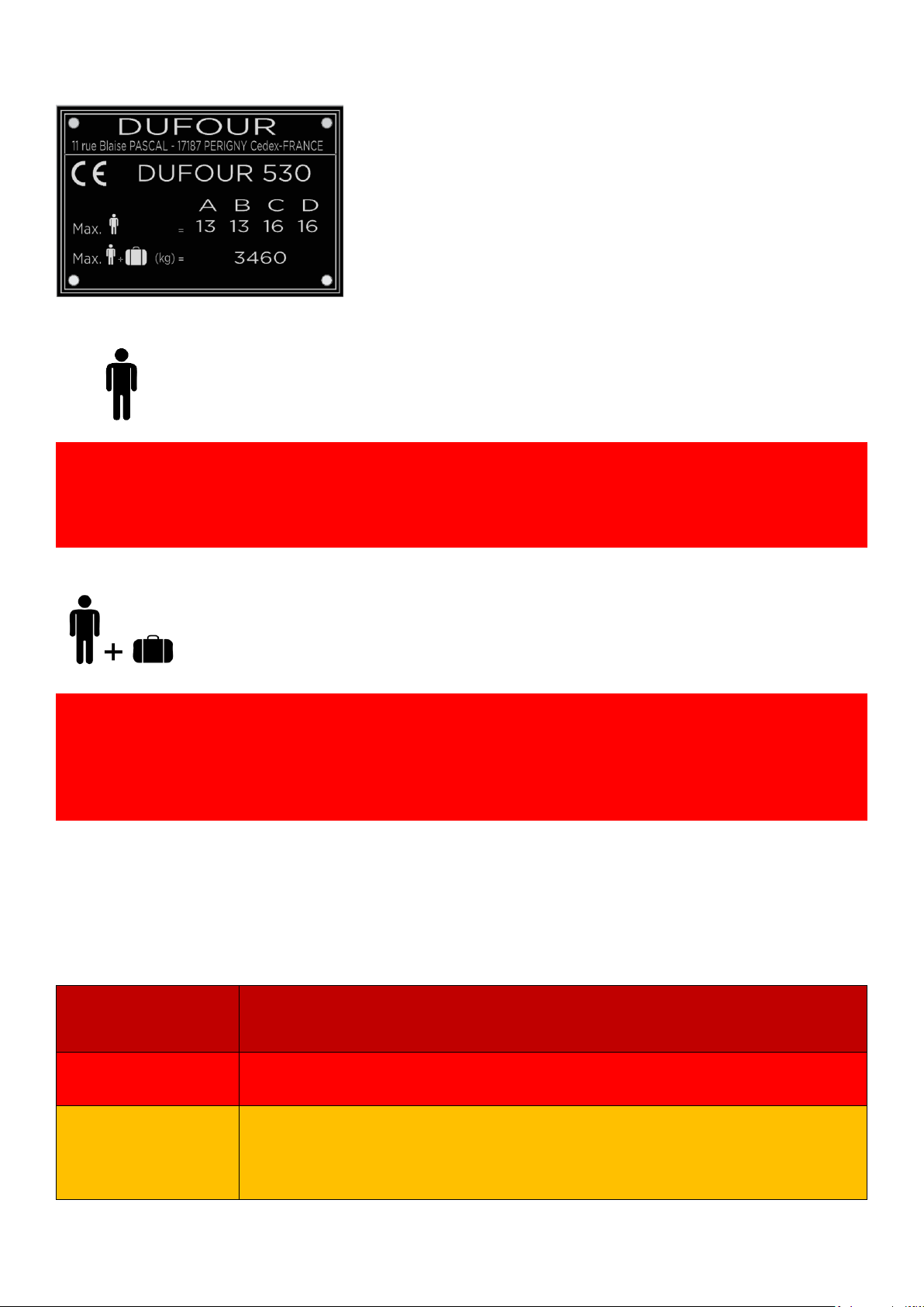
BUILDER'S PLATE................................................................................................................................................................................. 9
DEGREES OF DANGER ........................................................................................................................................................................... 9
II. PRINCIPAL SPECIFICATIONS............................................................................................................................................. 10
WEIGHTS AND DISPLACEMENTS............................................................................................................................................................ 11
SPECIFIC INFORMATION ...................................................................................................................................................................... 11
III. ELECTRICAL SYSTEMS........................................................................................................................................................... 12
SAFETY AND OPERATING INSTRUCTIONS FOR THE ELECTRICAL SYSTEM........................................................................................................... 12
FITTING NEW EQUIPMENT ................................................................................................................................................................... 12
BATTERIES ....................................................................................................................................................................................... 13
ELECTRIC WINDLASS........................................................................................................................................................................... 13
220/110 VOLT INSTALLATION (ISO 13297:2000)................................................................................................................................ 13
................................................................................................................................................................................................. 14
IV. GAS INSTALLATION.............................................................................................................................................................. 15
GENERAL INFORMATION..................................................................................................................................................................... 15
OPERATION OF THE LPG SYSTEM.......................................................................................................................................................... 15
CHECKING THE SYSTEM....................................................................................................................................................................... 15
SAFETY WARNINGS ............................................................................................................................................................................ 16
DETECTION SYSTEM ........................................................................................................................................................................... 16
V. DRAIN & SANITATION SYSTEM............................................................................................................................................. 17
CHARACTERISTICS OF THE DRAIN SYSTEM (ISO 15083:2003) ................................................................................................................... 17
PRESSURIZED FRESH-WATER PUMP ....................................................................................................................................................... 17
SEACOCKS........................................................................................................................................................................................ 17
OPERATION OF THE SEA TOILETS........................................................................................................................................................... 18
HOLDING TANK OPERATION (ISO 8099:2000) ...................................................................................................................................... 18
VI. FLOODING ........................................................................................................................................................................... 18
VII. FIRE PROTECTION............................................................................................................................................................... 19
INSTALLATION................................................................................................................................................................................... 19
SAFETY INSTRUCTIONS........................................................................................................................................................................ 20
VIII. ENGINE.............................................................................................................................................................................. 21
GENERAL PRECAUTIONS...................................................................................................................................................................... 21
EXHAUST GAS EMISSION ..................................................................................................................................................................... 21
SAFETY............................................................................................................................................................................................ 21
WINTERING ..................................................................................................................................................................................... 22
IX. FUEL INSTALLATION ............................................................................................................................................................ 22
X. HELM SYSTEM ...................................................................................................................................................................... 22
HELM ............................................................................................................................................................................................. 22
EMERGENCY TILLER............................................................................................................................................................................ 23
XI. SAILING ............................................................................................................................................................................... 24
FIELD OF VISION................................................................................................................................................................................ 24
XII. FALL PREVENTION AND MEANS OF GETTING BACK ABOARD.............................................................................................. 25
XIII. LIGHTNING PROTECTION................................................................................................................................................... 26
MAINTENANCE ................................................................................................................................................................................. 26

ENGLISH 28-04-2020 6/97 DUFOUR 530
PERSONAL PROTECTION DURING THUNDERSTORMS .................................................................................................................................. 26
XIV. ENVIRONMENTAL PROTECTION & SAFETY ........................................................................................................................ 26
XV. SAFETY FACILITIES .............................................................................................................................................................. 27
XVI. HANDLING, TRANSPORTING, HAUL-OUT ........................................................................................................................... 27
XVII. MOORING, ANCHORING, AND TOWING........................................................................................................................... 28
RESPONSIBILITY................................................................................................................................................................................. 28
XVI. GUARANTEE, TRANSFER OF OWNERSHIP .......................................................................................................................... 29
1. PRESENTATION................................................................................................................................................................ 34
2. ACCOMMODATION LAYOUT ........................................................................................................................................... 35
3. DECK FITTINGS LAYOUT................................................................................................................................................... 37
4. SAIL PLAN........................................................................................................................................................................ 39
5. RUNNING RIGGING, SHEETS AND HALYARDS LAYOUT..................................................................................................... 41
6. 220V ELECTRICAL PANEL DIAGRAM................................................................................................................................. 47
7. 220V CIRCUIT DIAGRAM.................................................................................................................................................. 49
8. 220V CIRCUIT DIAGRAM WITH OPTIONS ......................................................................................................................... 51
9. 220 V ELECTRICAL INSTALLATION DIAGRAM ................................................................................................................... 53
10. FUSE LOCATION DIAGRAM .............................................................................................................................................. 55
11. CHARGING AND POWER SYSTEM DIAGRAM.................................................................................................................... 57
12. 12V ELECTRIC PANEL ....................................................................................................................................................... 60
13. ELECTRICAL PANEL REAR WIRING.................................................................................................................................... 62
14. 12V ELECTRICAL INSTALLATION DIAGRAM ...................................................................................................................... 66
15. LIGHTING CIRCUIT ........................................................................................................................................................... 68
16. RUDDER SYSTEM DIAGRAM ............................................................................................................................................ 70
17. GAS SYSTEM DIAGRAM ................................................................................................................................................... 72
18. ABANDON SHIP PLAN...................................................................................................................................................... 74
19. FRESHWATER SYSTEM DIAGRAM .................................................................................................................................... 77
20. DRAINAGE SYSTEM DIAGRAM......................................................................................................................................... 79
21. SKIN FITTING LOCATION DIAGRAM ................................................................................................................................. 81
22. MECHANICAL INSTALLATION DIAGRAM .......................................................................................................................... 83
23. GAS SYSTEM DIAGRAM ................................................................................................................................................... 87
24. ENGINE VENTILATION CIRCUIT ........................................................................................................................................ 89
25. HOLDING TANK INSTALLATION DIAGRAM....................................................................................................................... 91
26. LIFTING DIAGRAM........................................................................................................................................................... 93
27. NAVIGATION LIGHTS ....................................................................................................................................................... 95

ENGLISH 28-04-2020 7/97 DUFOUR 530
INTRODUCTION
DUFOUR is pleased to present you with this manual, which will help you get to know your boat better.
This Manual has been produced to help you use your boat safely and enjoyably. It contains details of the
boat, the equipment supplied or fitted, its systems and information about their use. Read it carefully and
familiarize yourself with the boat before using it.
This Owner’s Manual is not a course in sailing safety or seamanship. If this is your first boat or you are
changing to a type of boat you are unfamiliar with, for your convenience and safety, make sure you gain
experience in handling and using it before taking command. Your agent, national sailing or cruising
federation or yacht club will be happy to give you information about sailing schools or qualified instructors in
your area.
Ensure that forecast wind and sea conditions correspond to the design category of your boat, and that you
and your crew are capable of handling the boat in these conditions. Even when your boat is suitable for
them, the sea and wind conditions corresponding to design categories A, B, and C vary from severe storm
for category A to severe conditions for the top end of category C, subject to dangers of abnormal gusts or
waves; these are dangerous conditions in which only an experienced, trained crew in good shape, sailing a
properly-maintained boat, can sail in a satisfactory manner.
This Owner's Manual is not a detailed maintenance or repair guide. In the event of problems, consult the
boatbuilder or their representative. If a maintenance manual is provided, be sure to use it.
Always employ the services of an experienced professional for maintenance, fitting accessories, or
modifications. Modifications that could affect the characteristics of the boat must be assessed, performed
and documented by qualified personnel. The boatbuilder cannot be held responsible for modifications made
without their approval.
In certain countries, a skipper's license or some form of authorization is required, or special rules and
regulations are applicable.
Always maintain your boat correctly and make allowances for deterioration due to age or resulting, where
applicable, from heavy or unsuitable use. Any boat, however sturdy, can be severely damaged if it is used
incorrectly. This is incompatible with safe sailing. Always suit your speed and heading to the prevailing sea
conditions.
If your boat is equipped with a life raft, read its instruction manual carefully. The crew must have all the
safety equipment on board (life-jackets, harnesses, etc.), corresponding to the type of boat, weather
conditions, etc. In some countries, this equipment is mandatory. The crew must be familiar with the use of
all the safety equipment and the emergency safety procedures (man overboard recovery, towing, etc.);
training sessions are regularly organized by sailing schools and clubs.
It is recommended that all persons wear appropriate buoyancy aids (life-jackets, personal flotation devices)
when on deck. It should be noted that in certain countries, it is compulsory to wear a buoyancy aid
(complying with national regulations) at all times.
KEEP THIS MANUAL IN A SAFE PLACE AND PASS IT ON TO THE NEW OWNER IF YOU
SELL THE BOAT.
WARNING: Our boats are regularly improved in light of our customers’ experiences and research
carried out by the shipyard. As a result, the specifications given in this Owner’s Manual are not
contractually binding and may be changed without notice and without any obligation to update
them. This manual is intended to cover as much information as possible, so certain equipment or
paragraphs might not apply to your boat. In case of doubt, please refer to the inventory which
should have been given to you by your agent when you placed your order.

ENGLISH 28-04-2020 8/97 DUFOUR 530
I. GENERAL INFORMATION
Yacht design category
Your DUFOUR 530 enters into design category OCEAN (category A).
Under normal conditions of use, your boat is designed to sail in waves of a significant height over
4 m, winds of Beaufort force 8 and above, and to resist under more severe conditions.
This navigational capacity also depends on the skill of the crew, their physical capacity, boat
maintenance and equipment.
So always take care before putting to sea.
DUFOUR YACHTS is not able to guarantee perfect functioning of the boat in exceptional sea
conditions (violent storms, hurricanes, cyclones, waterspouts, etc.)
SUMMARY OF DESIGN CATEGORIES
Yacht
Design
Categories:
Type of
sailing
Wind
strength
(Beaufort)
Wind
speed
Significant wave height
to be taken into account
A
Ocean
Above 8
Up to 28
m/s
Above 4 m
B
Open sea
Up to 8
Up to
21m/s
Up to 4 m inclusive
C
Near the
coast
Up to 6
Up to 17
m/s
Up to 2 m inclusive
D
In protected
waters
Up to 4
Up to 13
m/s
Up to 0.5 m inclusive
Note: Significant wave height equals the average of the highest one-third of the waves, which
approximately corresponds to the wave height estimated by a trained observer. Some waves will
reach twice this height.
Check weather conditions before sailing: Take to the sea, don’t take risks!
In port: every day, the Harbour Master's Office posts weather bulletins and forecasts for the next
few days.
Météo France on 08 36 68 08 08
Navifax - direct on 08 36 70 18 52
VHF: CROSS transmits several bulletins per day, preceded by an announcement on
Channel 16.
Certification
DUFOUR has chosen Institut pour la Certification et la Normalisation dans le Nautisme as the
notified body to check the conformity of your boat with European Directive 2013/53/EU of 20
November 2013, under certification module B.
Identification
The hull identification number is located on the starboard side of the transom. It contains a series
of letters and numbers that begin with FR-DUF...

ENGLISH 28-04-2020 9/97 DUFOUR 530
Builder's plate
Some of this information is provided on the builder’s
plate attached to the boat. A full explanation of this
information is given below.
Yacht design category = A : Ocean (see 1.1)
Max. number of people:
Category A = 13
Category B = 13
Category C = 16
Category D = 16
WARNING
Do not exceed the maximum recommended number of people. However many people there are
aboard, the total weight of the people and equipment must never exceed the maximum
recommended load.
Max recommended load:
Category A = 3460 kg
Category B = 3460 kg
Category C = 3460 kg
Category D = 3460 kg
WARNING
When loading the boat, never exceed the recommended maximum load.
Always load the boat carefully and distribute the weight in a suitable manner in order to maintain
the theoretical trim (approximately horizontal). Avoid placing heavy loads in the upper parts.
CE
Degrees of danger
DANGER
Indicates an extreme intrinsic risk that presents a high probability of
death or permanent injury if proper precautions are not taken.
WARNING
Indicates a risk that presents a high probability of death or
permanent injury if proper precautions are not taken.
CAUTION
Indicates a reminder about safety-related practices, or points out
dangerous practices that could result in personal injury or damage to
the boat or its components, or to the environment.
recommended by the builder when the boat sails
under sea conditions that correspond to its design
category.
recommended by the manufacturer including the
weight of all passengers aboard, provisions and
personal belongings, in addition to all equipment
not included in the boat’s light displacement, but
excluding the contents of the tanks.
: CE marking indicating the boat’s compliance
with the essential requirements of Directive
2013/53/EU. (See Written Declaration of
Compliance)

ENGLISH 28-04-2020 10/97 DUFOUR 530
II. PRINCIPAL SPECIFICATIONS
Model:
DUFOUR 530
Constructor
Dufour
11, Rue Blaise Pascal
17187 Périgny cedex
FRANCE
Architecture:
Umberto Felci
Interior design
DUFOUR Design
Yacht design category
A
No. of the notified body
CE/0607
CIN No.
Primary means of propulsion
Sail
Lmax
Length overall *
16.35 m
LH
Hull length*
15.50 m
Bmax
Maximum beam*
4.99 m
BH
Hull beam*
4.99 m
HA
Maximum air draft*
23.25 m
Tmax
Draft (Shallow / deep keel / VDD) *
2.05 / 2.40 / 2.90 m
Keel weight (shallow / deep / VDD)
4950 / 4700 / 4600 kg
Standard mainsail area (approx.)
65 m²
Self-tacking jib area (approx.)
45 m²
Maximum permissible on-board engine power
110 CV / 81 kW
Water capacity excl. 60 L (approx.) water heater
680 L
Diesel capacity (approx.)
430 L
Holding tank –depending on the version
Up to 235 L
Engine battery
105 Ah
Auxiliary battery (optional)
Minimum 560 Ah
* The above specifications comply with ISO 8866, i.e.:
Lmax: maximum length of the boat including normally fixed parts such as bow rollers, pulpits, etc.
LH: maximum length of the vessel including structural elements that are an integral part of the
vessel, and excluding removable parts.
Bmax: breadth of the vessel measured between the outermost portions, which may include
detachable parts such as top rails, railings, etc.
BH: breadth of the vessel measured between the outermost fixed portions and excluding all
removable parts
HA: vertical distance between the unladen water line and the highest point of the mast structure.
(this does not take into account equipment such as lights and antennas that may be attached to
the masthead)
Tmax: the maximum draft is measured at the lowest point of the boat’s keel under maximum load
conditions
N.B.: due to the trim and load of the boat, it is not usually possible to use all the various
tank capacities for fresh water and diesel. It is recommended that you maintain a diesel
reserve of 20%.

ENGLISH 28-04-2020 11/97 DUFOUR 530
Weights and displacements
A
B
C
D
E
F
G
MLC
16625
16875
16525
16682
16932
16674
16574
MMO
16918
17168
16818
16975
17225
16967
16867
mL
4499
4499
4499
4499
4499
4499
4499
MLDC
21124
21374
21024
21181
21431
21173
21073
mLA
19481
19731
19381
19538
19788
19530
19430
A = classic mast + deep keel version B = classic mast + shallow keel version
C = classic mast + very deep keel version D = furling mast + deep keel version
E = furling mast + shallow keel version F = performance mast + deep keel version
G = performance mast + very deep keel version
MLC: Boat's weight specification for light displacement
MMO: Boat's weight specification for minimum conditions of use
mL: maximum load used for the stability study, including the maximum recommended load (see
builder's plate) and 95% of the total weight of the various liquids (drinkable or not) contained in the
tanks.
MLDC: Boat's weight specification for maximum load conditions
mLA: Weight specification for the boat in maximum load conditions minus 85% of the stationary
tanks or tanks holding fuel, oil and drinking water and minus 90% of the edible provisions, but
including the combination of optional items of equipment or deck fittings least favourable for stability.
The total weight of liquids when all permanent tanks are full equals 1341 kg (including black water
tanks: the scenario taken into account is the most restrictive).
Specific information
This vessel has been assessed with the help of the StabilityIndex (STIX), a measure of overall safety
with regard to stability, which takes into account the effects of the length of the vessel, its
displacement, hull proportions, stability characteristics and its resistance to flooding.
The second index (AVS, angle of vanishing stability) represents the heel angle at which stability is
lost, in degrees.
Minimum operating
condition (MMO)
Loaded arrival
condition
(MLA)
STIX
41.24
35.51
AVS
114.8°
109.6 °
These values are those of the deep-keel version with a classic mast.

ENGLISH 28-04-2020 12/97 DUFOUR 530
III. ELECTRICAL SYSTEMS
Safety and operating instructions for the electrical system
WARNING
Improper use of the DC and/or AC systems may give rise to fire or explosion hazards.
Improper use of the AC systems may give rise to electrocution
hazards.
Always:
● Check the condition of the batteries (charge and electrolyte level) and the charging system
before putting to sea.
● Disconnect and remove batteries for wintering.
● Do not let battery voltage drop below 12 V during wintering.
● Carry spare bulbs for all navigation lights and interior lighting.
Respect power ratings, particularly for navigation lights.
● Check the operation of navigational instruments.
● Check the operation of navigation lights before sailing at night.
Never:
● Work on an electrical installation under voltage.
● Modify an installation or the relevant layouts, unless performed by a qualified naval electrician.
● Change or modify the circuit breaker capacity of protection devices.
● Replace the devices or electrical equipment by elements that exceed the prescribed capacity
without recalibrating conductors and protection devices.
● Leave the boat unattended when the electrical installation is under voltage, except for an
automatic bilge pump and protection circuits against fire or theft.
If a fuse or circuit-breaker trips repeatedly, you should consult a specialist to determine the cause of
the short-circuit.
Fitting new equipment
Since 1 January 1996, electrical equipment is subject to the European Directive on ''electromagnetic
compatibility'' (Ref 89/336/EEC). It is therefore necessary that any new equipment you may wish to
install meets the requirements of this standard and bears the CE mark. Equipment must also be
supplied with a compliance certificate and instructions for use.
In the case of 220 or 110 V installations, use only double-insulated or earthed equipment. Respect
the instructions for installation when installing these devices (wire gauge, protection).
To avoid maintenance problems, note any modifications to the electrical layout in the manual.

ENGLISH 28-04-2020 13/97 DUFOUR 530
Batteries
The battery installation consists of four 140 Ah standard auxiliary batteries (plus additional optional
batteries) and one 105 Ah engine battery.
Their capacities have been designed to handle the power requirements of the on-board accessories.
To avoid any problems, it is necessary to keep a close eye on the maintenance and correct charging
of the batteries.
CAUTION!
When you install new electrical devices, make sure that the overall consumption of these
devices remains proportional to the capacity of your batteries.
When disconnecting or replacing batteries:
Always disconnect the negative (-) battery terminal before the positive (+) terminal.
Never allow a conductive object (tools, etc.) to bridge across the two battery terminals.
When handling batteries, avoid any leakage of electrolyte liquid by keeping them horizontal.
Wear gloves and proper clothing to avoid any risk of contact with the electrolyte in the event
of a leak.
In the event of a projection of electrolyte, thoroughly rinse the part of the body concerned and
consult a doctor
Never add distilled water to a maintenance-free battery
Battery installations should be replaced in their entirety
Do not connect batteries that use different technologies
Do not connect batteries whose capacities and lifespans differ by more than 10%
Electric windlass
CAUTION!
When you use the electric windlass, it is essential to run your engine with a slight acceleration.
220/110 Volt Installation (ISO 13297:2000)
DANGER!
The on-board 220V installation is protected by a circuit breaker and fitted with a residual current
device. The wiring of additional 220V on-board accessories must be carried out by professionals
and the master circuit-breaker uprated if necessary.
-Do not modify the electrical installation of the boat or the relevant layout. Installation, modification
and maintenance should be carried out by a qualified naval electrician. Have the system checked
every 2 years
-Disconnect the boat power supply when the system is not in use.
-Connect the metallic housing of on-board electrical devices to the boat’s protection conductor
(green conductor or green with a yellow stripe).
-Use double-insulated or earthed electrical appliances.
CAUTION!
When the boat is moored at the quayside, set the isolator to the open position.

ENGLISH 28-04-2020 14/97 DUFOUR 530
DANGER!
Your boat is not supplied with a shore/boat supply cable or a male plug for the shore outlet. The
cable must be suitable for outdoor use. Its diameter should be adapted to its length and the power
of the main circuit breaker (See the electrical diagram).
The plug must be suitable for the shore socket (if necessary, seek professional advice). It should
be as close as possible to the IP 67/IEC529 type
WARNING: To reduce the risk of electric shock and fire.
● Switch off the shore supply at the on-board isolator before connecting or disconnecting the
shore/boat supply cable.
● Connect the shore/boat supply cable to the boat before connecting it to the shore outlet.
● Disconnect the shore/boat supply cable at the shore outlet before disconnecting it from the
boat.
● Properly close the protection of the power supply inlet when docked
Never:
● Make any modifications to the shore/boat supply cable connections: use only compatible
connectors.
● Swim near a boat connected to a shore supply socket: risk of electrocution!
Location of the 220 V master circuit breaker: the rudder cable cache in the aft port cabin.
Have the system checked at least every 2 years.
During haul-out maintenance, set to the closed position in order to have earth [grounding]
protection via the shore socket.
WARNING
Never let the extremity of a ship/shore supply cable dangle into the water. It may create an
electrical field that could injure or kill nearby swimmers.
WARNING –RISK OF ELECTRIC SHOCK - INVERTER
If the boat is equipped with an inverter that changes direct current (DC) into alternating current
(AC), in order to avoid any risks of injury or death due to electric shock, disconnect the AC shore
supply line and the DC supply from the inverter before opening any electric panels or performing
any work on the circuits.

ENGLISH 28-04-2020 15/97 DUFOUR 530
IV. GAS INSTALLATION
General Information
-Pressure for use: 30 mbar (see indication on the label in the gas locker and on the regulator
valve)
-Vents to use for the evacuation of burnt gas: hatch above the cooker and companionway
-Do not obstruct quick access to the elements of the gas installation (cylinder locker, shut-off
valve).
-Regularly inspect the hoses at least once a year and change them if damaged, if the expiry
date is exceeded, or five years after the manufacture date printed on the hose.
-Valves attached to empty cylinders must be closed and disconnected. Protective covers, caps
and plugs must be kept in place. Gas cylinders (including reserve cylinders) must be kept in
housings or lockers for LPG cylinders with ventilation to the exterior, or stored at the exterior of
the boat, protected from weather and mechanical damage, and in such a way that any leaking
gas can only escape to the exterior of the boat.
-The locker for LPG cylinders must not be used for the storage of any other equipment.
-Ensure that the gas cylinder and regulator comply with the requirements of the cooker (flow
rate, pressure, type of gas) and with the regulations in force in the country where it is being
used.
-Make sure that all valves are closed when replacing gas cylinders.
Operation of the LPG system
-The valves of the supply lines and cylinders must be closed when the devices are not used or
before filling, and must be immediately shut off in case of emergency.
-The valves of the appliances must be closed before opening the cylinder valve.
WARNING
Fuel-burning naked-flame appliances use up the oxygen in the cabin and release combustion
products inside the vessel. Proper ventilation is necessary:
Open the deck hatch or porthole located nearby as well as the companionway when the
appliances are in operation.
-The cooker is suspended and can therefore be used when under sail. However, limit its use
when large angles of roll or heel are likely.
Checking the system
-The LPG system should be checked for leaks before each use as follows:
-Close the valve of the appliance, open the LPG cylinder valve, allow the pressure of the
pressure gauge to stabilise, close the valve of the LPG cylinder, check the pressure indicated
by the pressure gauge located near the cylinder for three minutes. The pressure indicated by
the pressure gauge should be constant if there is no leak in the system.
-Information: the pressure gauge does not give an indication of the quantity of liquid LPG
remaining in the cylinder but only its vapour pressure, which is a constant at a given
temperature.
-If a leak of LPG is detected or suspected, immediately take the following steps:
-Cut off the supply at the main supply valve(s).
-Extinguish any naked flames and other sources of combustion (heating appliances, cooking
appliances, lights, etc.)
-Do not operate any electrical switches.
-Evacuate the area, if possible.

ENGLISH 28-04-2020 16/97 DUFOUR 530
WARNING
● Do not use an installation with a leak before it has been inspected and repaired by a
competent person.
DANGER!
Never use a naked flame to look for leaks.
-N.B.: The tests above do not replace the recommended periodic inspection by a professional.
Safety warnings
WARNING
Never leave the boat unattended when naked flames are in use
Refrain from smoking or using a naked flame while LPG cylinders are being changed.
Close the valve on the empty cylinder before disconnecting it to change. Properly ventilate the
cylinder compartment when replacing cylinders.
Do not use the cooker/oven as a heating appliance.
If a leak is detected, close the main LPG supply and do not use LPG appliances.
After the boat has been shut up, never smoke when going below, and ensure that there is no
smell of gas.
Do not modify the boat’s LPG system. Installation, modification and maintenance must be
carried out by a competent person. Have the system inspected at regular intervals or at intervals
fixed by national requirements.
CAUTION!
Certain precautions must be taken to avoid any contact with naked flames or other hot areas.
Do not use solutions containing ammonia during manual tests for leaks
Detection system
The boat must be equipped with a fire alarm system (smoke detector, heat detector, etc.).
The recommended location is indicated on the evacuation plan.
This detector emits an audible signal in the case of an alert.
It has an independent battery that must be replaced when it indicates a loss of power, in
compliance with the manufacturer’s instructions or those indicated on the device.
It is essential to carry out a routine test at each boarding or every week in the case of prolonged
presence on board.
If the test shows that the device is faulty, it should be replaced by an equivalent device.

ENGLISH 28-04-2020 17/97 DUFOUR 530
V. DRAIN & SANITATION SYSTEM
Characteristics of the drain system (ISO 15083:2003)
Pump type
Theoretical flow rate
Manual
38 L @ 45 strokes/minute
12V automatic
3900 L/h
Read the operating and maintenance instructions for your boat’s bilge pump carefully.
WARNING
The bilge pump system is not designed to handle water entering as a result of holing of the hull.
It is intended to remove water coming from spray, leaks from seacocks or other moderate leaks.
CAUTION!
● The level of water in the bilges must be kept to a minimum
● Make sure that bilge pumps are in working order before putting to sea.
● Regularly clean the bilge and pump suction points or strainers to keep them free of any debris
that could obstruct them.
If the watertight bulkheads isolating the forepeak and afterpeak are fitted with valves, these
should be kept closed and only opened to drain water in the main bilge.
● Know where to find each hand pump and its handle.
● Locate the switch for the electric bilge pump on the electrical panel.
Pressurized fresh-water pump
Fresh water is supplied to the sink and washbasins by an electric pump. A filter is installed
upstream of the pump, and must be cleaned regularly.
Never allow the pump to run if the tank is empty. Refill the tank before using the water
supply again.
The tanks can be sterilized using Clonazone® tablets (available from pharmacies). Every year,
remove the inspection covers and clean them by filling with water containing a bactericidal
detergent; leave it to act for a few hours, then rinse two or three times. During wintering,
completely fill the tanks to avoid the development of algae or bacteria. If there is a risk of freezing,
empty the tanks; never use anti-freeze.
Hot water is produced by a water-heater connected to the engine cooling circuit and the shore
electric supply.
After the water-heater has been emptied, make sure that the element is covered before power is
re-applied.
Seacocks
Seacocks are of the ¼-turn type:
- OPEN position: handle in the direction of the seacock body,
- CLOSED position: handle perpendicular to the seacock body.

ENGLISH 28-04-2020 18/97 DUFOUR 530
CAUTION!
● Never interfere with the tightening of the seacocks to the hull. In the event of a leak, consult a
professional.
● In bad weather or when leaving your boat, close all the sanitation system seacocks.
● Keep the seacocks closed when not in use and remember to manipulate them regularly to
maintain their flexibility of use. An unused seacock can eventually seize up.
● During wintering, clean and rinse the seacocks and skin fittings. Inspect brass fittings; slight
surface corrosion is normal.
● In the event of more serious corrosion, consult your agent.
Operation of the sea toilets
-Open the sea water inlet cock.
-Open the bowl emptying seacock.
-Set the lever to the “FLUSH” position.
-Operate the pump.
-To empty the bowl and avoid any water slopping when heeling, set the lever to the “DRY
BOWL” position.
-Operate the pump until the bowl is dry.
-Repeat these flushing/emptying operations as many times as is necessary to ensure complete
emptying of the pipes.
-When toilets are not being used, set the lever to the "DRY BOWL" position, or the "CLEF"
position for certain models.
-Close seacocks after use, as the toilet is below the waterline.
-Change the toilet seals regularly.
Holding tank operation (ISO 8099:2000)
CAUTION!
Where a holding tank is fitted, take care to lock the discharge valve, to avoid any accidental
discharge during wintering.
-Black water tanks (50 L) operate with the manual toilet pump.
-The contents of the toilet pan are discharged straight into the holding tank.
-Periodically check that the vent is working properly.
-A deck plate is provided for emptying the tank.
-The discharge valve can be sealed in the closed position using a padlock.
-Once a season, arrange to clean out the tank using a biodegradable disinfectant chemical.
Leave the system empty if the vessel is to be left in below-freezing temperatures. During winter
lay-up, use a food-grade, non-toxic antifreeze that complies with local regulations.
VI. FLOODING
To avoid the risk of flooding the boat:
Vanne ouverte Vanne fermée

ENGLISH 28-04-2020 19/97 DUFOUR 530
-Check that portholes, deck hatches, and any other openings that may cause flooding, are
closed before putting to sea.
-While under way, close all seacocks when they are not in use, except for the engine water
intakes.
-Do not exceed the maximum recommended loading.
-The level of water in the bilges must be kept to a minimum.
-Avoid adding weight in high places so as not to affect the stability.
Periodically check:
-Skin fittings, seacocks and pipes for watertightness.
-Proper emptying of the cockpit drains.
-Stern glands or sail-drive seals for watertightness.
WARNING
Cockpit locker covers must be fastened shut before putting to sea. This is particularly important
for lockers with a serious risk of flooding
VII. FIRE PROTECTION
Installation
Since fire extinguishers are subject to national regulations, they are not supplied with the boat.
However, when in use, this boat must be fitted with portable extinguishers with the following
capacities, installed in the following locations (see drawing in Appendix 17):
- No. 1 - cockpit locker, within reach of the helmsman - capacity 1 kg - 5A34B
- No. 2 –lounge near the companionway - extinction capacity 1 kg - 5A34B
- No. 3 –forward cabin - extinction capacity 1 kg - 5A34B
- No. 4 –skipper's cabin (if available)
If you decide to install a carbon dioxide (CO2) extinguisher, be aware that it may only be fitted in
accommodation areas that contain powered electrical equipment (e.g. electric motors, battery
compartments, electrical panels) or flammable liquids (e.g. galley).
Only compatible replacement parts must be used in the fire protection system. They must bear the
same markings and be technically equivalent.
In addition, a fire blanket must be stowed near the galley, which can be very useful in the case of a
cooker fire caused by oil (e.g. saloon banquette).
Similarly, for safety on deck, a fire bucket equipped with a lanyard must be stored in an
immediately accessible locker.
If non-combustible materials are stored in the engine compartment, they must be secured to avoid
the risk of falling onto the machinery and must not obstruct access to the engine compartment or
its exit.
WARNING
If a CO2 extinguisher is fitted, the following information must be displayed close to its location:
“This extinguisher contains CO2 - use only on electrical or cooker fires. To avoid suffocation
after discharging, leave the area immediately.
Ventilate before entering.”

ENGLISH 28-04-2020 20/97 DUFOUR 530
Do not open the engine compartment immediately after putting out a fire to avoid the release of
toxic smoke or spraying of burning materials (oil, water).
Safety Instructions
CAUTION!
It is the responsibility of the owner/skipper to:
● Have fire-fighting equipment checked in accordance with the stipulations of the builder and the
regulations in your country.
● Replace fire-fighting equipment if it has expired or been discharged, with extinguishers of
equal or greater capacity.
● Show members of the crew:
- The location and operation of fire-fighting equipment.
- the location of the engine compartment discharge hole
● Ensure that fire-fighting equipment is readily accessible whenever the boat is occupied.
● Always keep the bilge clean and check that there is no fuel or gas vapour and no fuel leak.
● Indicate escape routes.
Never:
● Obstruct passageways to the emergency exits (deck hatches).
● Obstruct safety controls (gas valves, fuel valves, electrical switches).
● Obstruct fire extinguisher stowages.
● Leave the boat unattended with a cooker or heater on.
● Use a gas lamp in the boat.
● Fill a fuel tank or change a gas cylinder while the engine is running, or the cooker or heater are
on.
● Smoke while handling fuel or gas.
● Place free-hanging curtains near the cooker or any other appliance which has an open flame.
● Store flammable substances in the engine compartment.
● Modify, or allow any non-qualified person to modify, any of the boat’s installations (especially
electrical, fuel, or gas).
Table of contents
Other Dufour Boat manuals
Popular Boat manuals by other brands

Stowaway Boats
Stowaway Boats K2 owner's manual

KAYAKS2FISH
KAYAKS2FISH NEXTGEN10 owner's manual

Grady-White Boats
Grady-White Boats Freedom 275 owner's manual

Yamaha
Yamaha GP800R WaveRunner 2003 Owner's/operator's manual

Ockelbo
Ockelbo B21 CAB owner's manual

Boston Whaler
Boston Whaler 190 Outrage user manual