View/Adjust Keytime
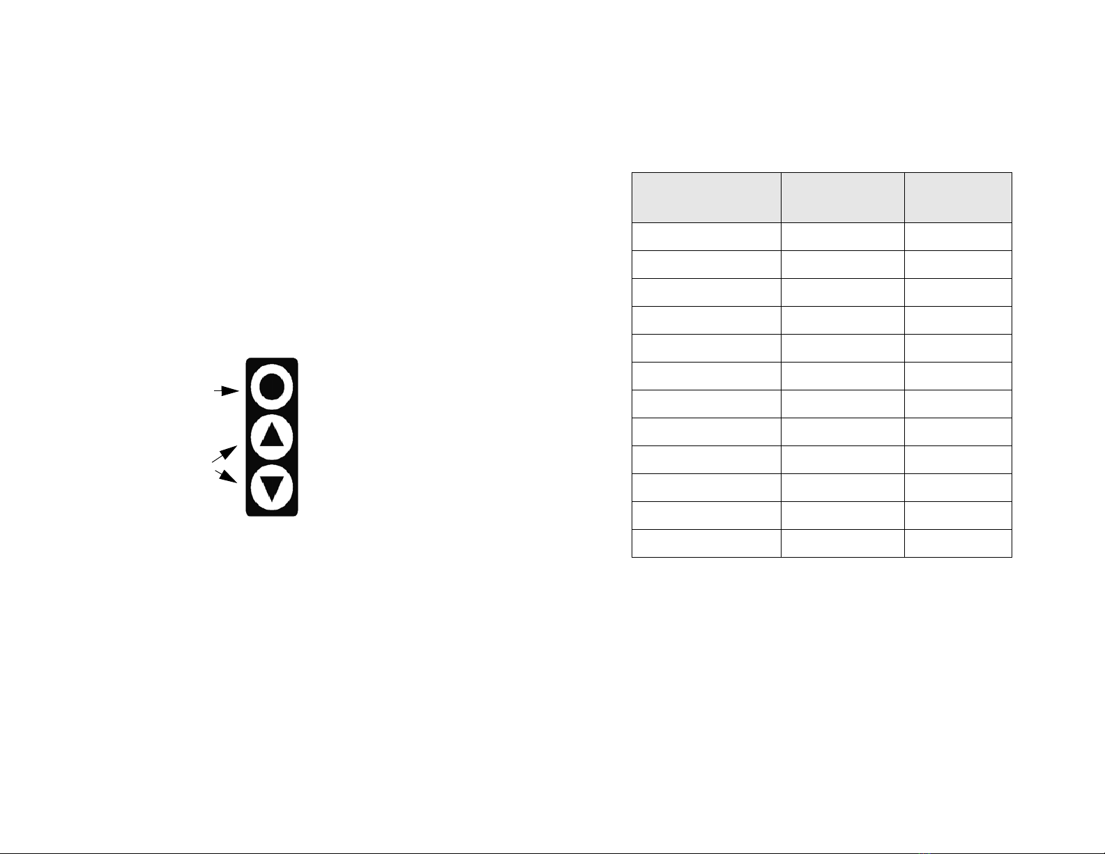
From AUTO mode, you can view the current keytime by pushing
MAIN twice, three times if running Brand-X rules. You cannot change
the keytime from this display . If you need to change keytime, press
and hold the MAIN button until “CLOCK” appears on the
display. Release the button. A “C” will be displayed on the left indicating
keytime can be adjusted. Adjust the keytime in increments of minutes
using the UP/DOWN buttons. The seconds are reset to zero each time
you change the minute. Hit the MAIN button to return to AUTO mode.
When you adjust your keytime in this mode you need to enter the
elapsed keytime since leaving the gate. If your backup watch displays
elapsed time then you can use this time directly. If it shows the actual
posted keytime you must subtract your minute before using it.
For AMA events, simply enter the time directly from your backup watch.
When running Brand-X, first set your minute to your original minute,
then adjust the clock to match your backup watch. After adjusting the
clock set your minute to your current minute.
Whichever rule you are running, adjust the clock so that the full minutes
match the backup watch. For example, if the backup shows 1:23:35,
set the computer clock to 1:23:00. When the backup seconds turn to
:00, increment the clock minute. Make sure they match then hit MAIN to
return to race displays. Adjust your minute if necessary.
Note: In Brand-X the keytime you see once back in race mode is
adjusted for your current minute. You can compare this directly to your
route sheet.
Adjusting Tire Size
At any time, to adjust your tire size, hold down the MAIN button until
“TIRESIZE” is displayed. Release the button. Now use the UP/DOWN
buttons to adjust your tire size in increments of 0.01 inches. Hit the
MAIN button to return to AUTO mode.
Tip: If your mileage is off by one one-hundredth (1/100) of a mile over
the course of a mile, adjust your tire size by about 0.80 inch.
Interactive Calculated Distance Mode (ICD)
In the event your magnet gets sheared off (or anytime), you can still use
WatchDog 2000 to display your differential time and calculated mile-
age. To enter ICD mode, press and hold MAIN button until “ ICD ON ”
is displayed. Calculated distance will be displayed on the left, and differ-
ential minutes and seconds will be displayed on the right. You will
immediately see the mileage change until the diff time is zero. The diff
time will remain 0:00 until you adjust the mileage. When you adjust the
20
Other Race Mode Displays
The following sections describes other race mode displays and how to
adjust race variables.
Adjusting Mileage
In MinuteMinderTM there are two ways to view and/or adjust your
mileage. To view or adjust the mileage hit either the UP or DOWN
button. The display switches to MileMinderTM. Then use the UP/
DOWN buttons to adjust your mileage.
If you initially hit the UP button to enter MileMinderTM , the display will
return to MinuteMinderTM after 4 seconds of no button activity. If you
initially hit the DOWN button the display will remain in MileMinderTM
until you hit the MAIN button.
When you hit the UP or DOWN button the displayed mileage stops
incrementing except for when you adjust it. If you are still moving, the
mileage is accumulated in the background. A few seconds after you
are done adjusting your mileage the accumulated mileage is added to
the displayed mileage. This allows you to adjust your mileage to match
a trail marker even though you are still moving forward. Just make sure
that you begin adjusting your mileage when you are next to the trail
marker.
Tip: Use the UP button to quickly view your mileage and adjust if
necessary. Use the DOWN button on road sections or fast sections
when you stay within your minute and want a constant display of your
mileage.
Tip: The longer you hold the UP/DOWN button the faster the mileage
will scroll.
Changing your Minute (Brand-X)
To change your minute in Brand-X racing, hit the MAIN button once
from AUTO mode. Your minute is displayed. Use the UP/DOWN
buttons to adjust. The display will return to the AUTO mode display after
4 seconds of no button activity, or after 10 seconds if you did not adjust
your minute.
Note: In AMA rules, your minute will not be displayed. Hitting the MAIN
button will display odometer and speedometer.
Tip: The display will automatically return to AUTO mode so don’t worry
about the display, adjust your minute and take off!!
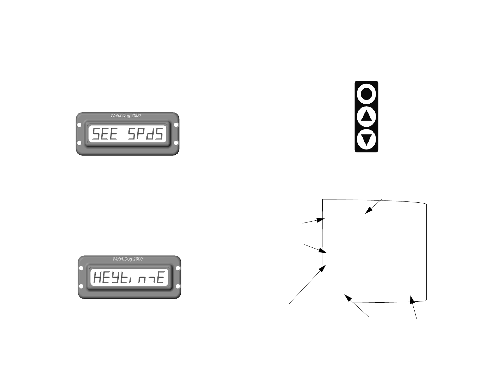
View Odometer and Speedometer
You can view your odometer and speedometer by pressing MAIN once
in AMA or twice in Brand-X. The speed is a 3 second running average.
19