Duke FBB-EC-208 User manual

Installation and
Operation Manual
BURGER KING
FLEXIBLE
BATCH BROILER –
ELECTRIC
DOMESTIC
Please read this manual completely before attempting
to install, operate or service this equipment
This manual is Copyright © 2014 Duke Manufacturing Co. All rights reserved.
Reproduction without written permission is prohibited. Duke is a registered
trademark of the Duke Manufacturing Co.
Duke Manufacturing Co.
2305 N. Broadway
St. Louis, MO 63102
Phone: 314-231-1130
Toll Free: 1-800-735-3853
Fax: 314-231-5074
www.dukemfg.com
P/N 177500
REV G 09/20/2017

Installation and Operation of Flexible Batch Broiler – Electric
2

3
Installation and Operation of Flexible Batch Broiler – Electric
TABLE OF CONTENTS
I. General Information......................................................................................................................5
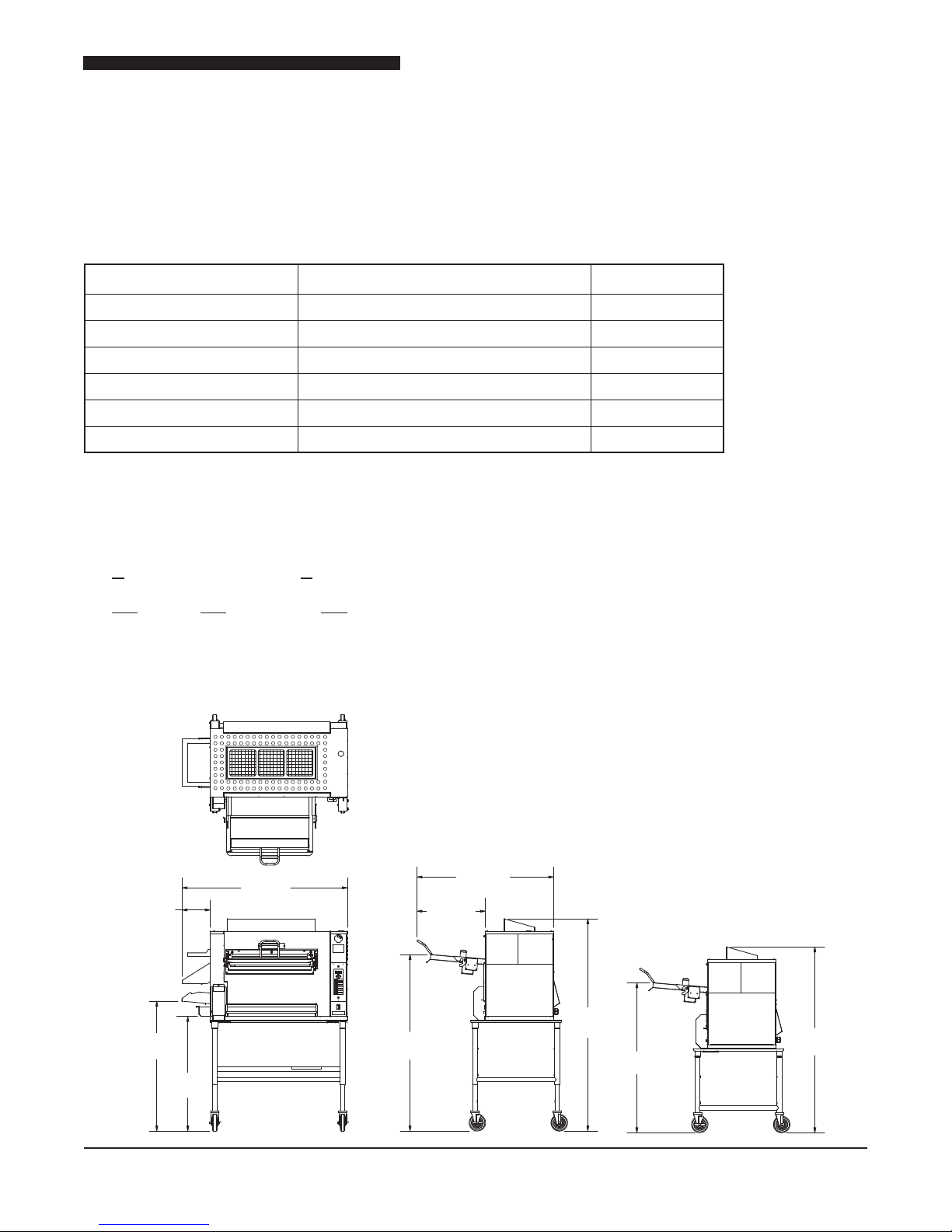
A.BatchBroilerSpecications................................................................................................. 5
A-1.0 Model Number Key................................................................................................. 5
A-2.0BroilerDimensions ................................................................................................ 5
II.InstallationInstructions................................................................................................................6
A.QualiedPersonnel............................................................................................................. 6
B.DeliveryandInspection....................................................................................................... 6
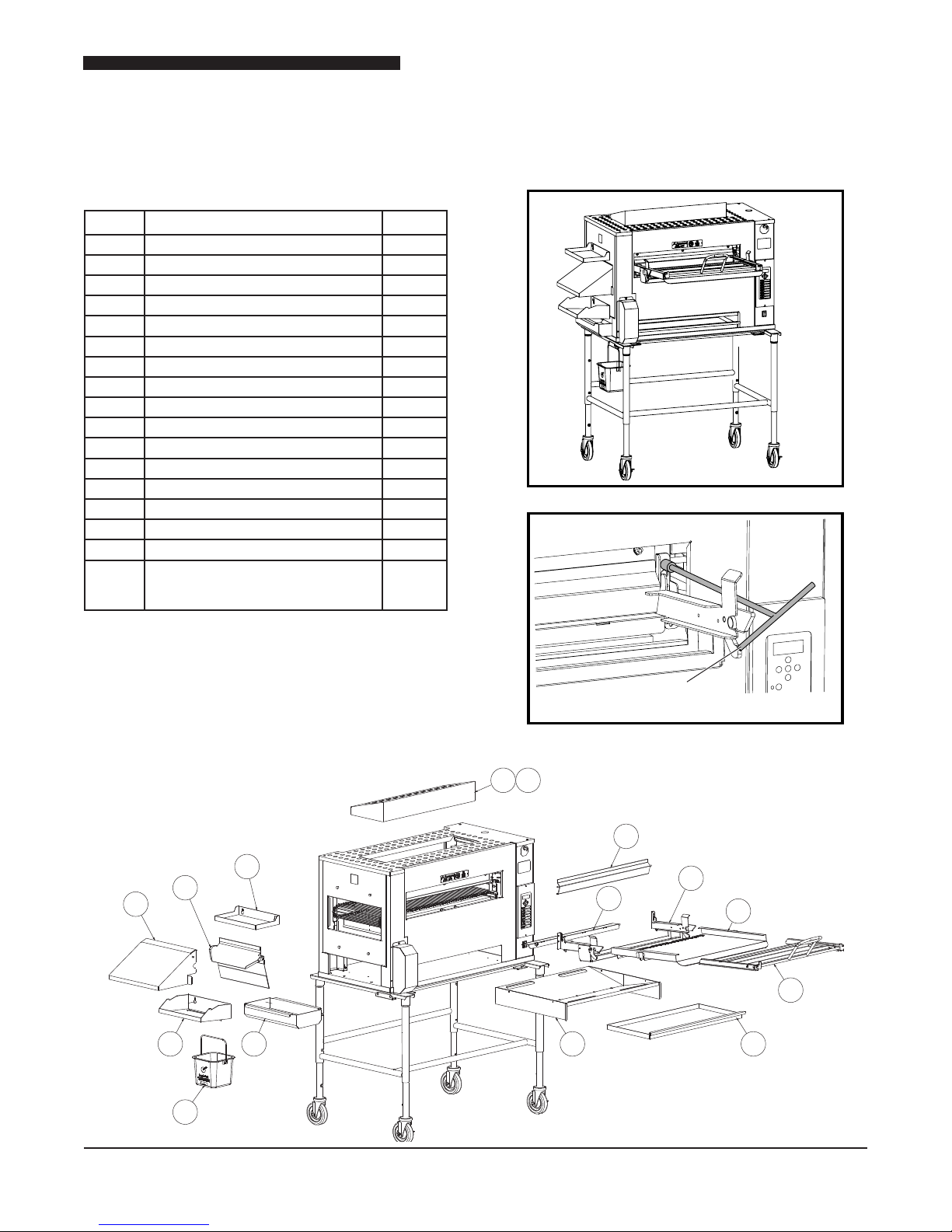
C.BroilerAssembly ................................................................................................................. 7
Setup................................................................................................................................ 7
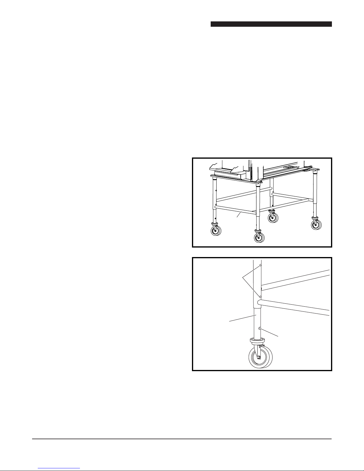
D.AdjustmentsatInstallation .................................................................................................. 8
RaiseorLowerBroiler .................................................................................................... 8
E.LocationoftheBroiler ......................................................................................................... 9
F.ElectricalConnections ......................................................................................................... 9
G. Ventilation ........................................................................................................................... 9
VentingtoaCanopyExhaustHood ................................................................................. 9
MaintenanceofVentilationSystem.................................................................................. 9
III.OperationInstructions ..............................................................................................................10
A.BroilerControls................................................................................................................. 10
B. Cooking Product.............................................................................................................. 11
B-1.0 Turning On the Broiler .......................................................................................... 11
B-2.0 Cook Product........................................................................................................ 11
B-3.0 Cook Cycle Complete........................................................................................... 12
B-4.0FineCookingAdjustment ..................................................................................... 12
B-5.0 Cancel a Cook Cycle............................................................................................ 12
B-6.0 Checking the Broiler Temperature........................................................................ 12
B-7.0 Checking the Set Point Temperature.................................................................... 12
B-8.0ShutdowntheBroiler ............................................................................................ 12
C. Cleaning.......................................................................................................................... 12
C-1.Four(4)HourCleaning ......................................................................................... 14
C-2. Daily Cleaning ........................................................................................................ 15
C-3. Weekly Cleaning ................................................................................................... 17
D. Programming the Control.................................................................................................. 20
D-1.0 Entering Program Mode ....................................................................................... 20
D-2.0NavigatingtheProgrammingScreens ................................................................ 20
D-3.0Level1Programming ......................................................................................... 20
D-3.1ProductIdentierAbCd ...................................................................................... 20
D-3.2CookingProleti1,SEt1,PL1,ti2,SEt2,PL2,… ................................... 20
D-3.3 Exit Program Mode ............................................................................................. 21
D-4.0Level2Programming ......................................................................................... 21
D-4.1 ºF or ºC Parameter dEg ..................................................................................... 21
D-4.2 Change the Idle Temperature iSEt ...................................................................... 21
D-4.3ChangetheIdlePowerLeveliPL........................................................................ 21
D-4.4ChangetheIHeatingElementVoltageSettingCSEn ........................................ 21
D-4.5AdditionalFactoryParameters ............................................................................. 21
D-4.6 Exit Program Mode ............................................................................................. 21
E.Troubleshooting................................................................................................................. 22
IV. Service and Repair...................................................................................................................23
A.Warnings ........................................................................................................................... 24
B.UserReplaceableHeatingElements ................................................................................ 24
V.ReplacementPartsList .............................................................................................................28
VI. Wiring Schematic ..................................................................................................................... 30

Installation and Operation of Flexible Batch Broiler – Electric
4
IMPORTANT WARNING AND SAFETY INFORMATION
FOR YOUR SAFETY:
Do not store or use gasoline or other ammable vapors or liquids
in the vicinity of this or any other appliance.
: Improper installation, adjustment, alteration, service or
maintenance can cause property damage, injury or death. Read the
installation, operating and maintenance instructions thoroughly before
installing or servicing this equipment.
THIS MANUAL MUST BE RETAINED FOR FUTURE REFERENCE.

5
Installation and Operation of Flexible Batch Broiler – Electric
I. GENERAL INFORMATION
A. Batch Broiler Specications
SHIPPING WEIGHT: 530lbs(240Kg)
SHIPPING DIMENSIONS: 47” x 34” x 68” (119.4 x 86.4 x 172.7 cm)
MODEL NUMBER ELECTRIC POWER
FBB-EC-208 208VAC,68A,60Hz,3Ph 23,500W
FBB-EO-208 208VAC,68A,60Hz,3Ph 23,500W
FBB-EC-230 230VAC,62A,60Hz,3Ph 23,500W
FBB-EO-230 230VAC,62A,60Hz,3Ph 23,500W
FBB-EC-240 240VAC,60A,60Hz,3Ph 23,500W
FBB-EO-240 240VAC,60A,60Hz,3Ph 23,500W
A-1.0 Model Number Key
FBB-EX-Y-ZZ
X = O(NOCATALYST)ORC(CATALYST)
Y = 208VOLTS,230VOLTSOR240VOLTS
ZZ = 2 DIGIT COUNTRY IDENTIFIER
A-2.0 Broiler Dimensions
(128 cm)
50 3/8"
(21.6 cm)
8 1/2"
(88.4 cm)
34 3/4"
(100.3 cm)
39 1/2"
(136.1 cm)
53 5/8"
(52.9 cm)
20 3/4"
(111.9 cm)
44"
(164.2 cm)
64 5/8"
(115.8 cm)
45 5/8"
(143.9 cm)
56 5/8"

Installation and Operation of Flexible Batch Broiler – Electric
6
II. INSTALLATION INSTRUCTIONS
A. QUALIFIED PERSONNEL
Theseinstallationinstructionsarefortheuseofqualied
installation and service personnel only.Installationor
servicebyotherthanqualiedpersonnelmayresultin
damage to the broiler and/or injury to the operator.
Qualiedinstallationpersonnelarethoseindividuals,rms,
companiesorcorporationswhicheitherinpersonorthrough
anagentisengagedinandresponsiblefor:
• Theinstallationofelectricalwiringfromtheelectric
meter, main control box or service outlet to the
electricalappliance.Qualiedinstallationpersonnel
must be familiar with all precautions required and
havecompliedwithallrequirementsofstateandlocal
authoritieshavingjurisdiction.See:NationalElectrical
Code,ANSI/NFPA70.
• This appliance is not intended for use by persons
(includingchildren)withreducedphysical,sensory
or mental capabilities, or lack of experience and
knowledge,unlesstheyhavebeengivensupervision
orinstructionconcerninguseoftheappliancebya
personresponsiblefortheirsafety.
B. DELIVERY AND INSPECTION
DukeManufacturingCo.doeseverythingwithinitspower
toinsureyoureceivedyourbroileringoodcondition.They
arestrappeddownonheavywoodenskidsandpacked
topreventshippingdamage.Theyhaveallbeencarefully
inspectedbeforetheywerepackagedandconsignedto
the carrier.
UpondeliveryofyourDukebroiler:
• Lookovertheshippingcontainer,carefullynotingany
exteriordamageonthedeliveryreceipt,whichmust
alsobesignedbythedriver/deliveryperson.
• Unpackandcheckforanydamage,whichwasnot
evidentontheoutsideoftheshippingcontainer.
• Checkforconcealeddamage.Thecarriermustbe
notiedwithinfteen(15)daysofthedeliveryofthe
broilerandthecarton,skidandallpackagingmaterials
mustberetainedforinspection.
DukeManufacturingCo.cannotassumeliabilityforloss
ordamagesufferedintransit.Thecarrierassumesfull
responsibilityfordeliveryingoodorderwhentheshipment
wasaccepted.However,wearepreparedtoassistyou
inlingyourclaim.
Caution: The broiler is very heavy!
Use adequate help when lifting.
2
3
5
4
6
7
4
4
5
8
1) Usingautilityknife,cutawayplasticwrap(Notshown).
2) Remove the top cardboard and inner cap.
3) Remove Training Material Box
4) Removecardboardfromthecorners(4places).
5) Removecardboardontheends(2places).
6) Remove banding straps (Cut with utility knife or scissors:
5places).
7) Removeboxofattachableparts&accessoriesfromthefront.
8) Safelyliftoneendofbroilerandtapblocktowardscenterand
thensidewaystoremove.Repeatforremainingblocks.This
allowscasterstotouchthepallet.
9) Remove the broiler from the shipping pallet using 3 people
to guide and distribute it’s weight (approx 335 lbs[152 Kg])
accordingly.Whilecarefullysupportingthebroiler.Rollitforward
untilthefrontcastersareclearofthepallet.Liftthebroiler6-8
inchesaboveandawayfromthepallet,andgentlyplaceon
oortoavoiddamagetocasters.
10) Remove protective blue tape from broiler panels, double
checkingthatnotaperemains.

7
Installation and Operation of Flexible Batch Broiler – Electric
1
11
12
13
9
10
2
3
4 5 6 7
8
16
15
C. BROILER ASSEMBLY
Before assembling and installing the broiler, please
checktomakesurethatallnecessarypartsarepresent.
Setup
Install all items as shown below.
Loader Install Tool
(Included with Broiler Tools Kit)
ITEM PART NAME
PT. NO.
1PRODUCTPANSHELF 175353
2DISCHARGECHUTE 175340
3DISCHARGEHOOD 175778
4DISCHARGEPANHOLDER 175358
5DISCHARGEGREASEPAN 175357
6 “V” GREASE PAN 177011
7 MAIN GREASE PAN 175329
8LOADER 175444
9LOADERTRAY 175430
10 LOADERBRACKET 175438
11 DOOR 175429
12 LOADERRAMP 175741
13 IMPEDANCE PAN 175226
14 CATALYST(OPTIONAL) 175480
15 CATALYSTGUARD(OPTIONAL) 175482
16 SANITATIONPAIL 175842
17 KIT,CLEANINGTOOLS/INSTALLATION
TOOLCLEANING–LOADERINSTALL
WRENCH,ALLEN,3/16"
600225

Installation and Operation of Flexible Batch Broiler – Electric
8
D. ADJUSTMENTS AT INSTALLATION
Eachbroilersectionandallitscomponentpartshave
beentestedthoroughlyandinspectedbeforeyourbroiler
wasshippedfromthefactory.However,itissometimes
necessarytofurthertestoradjustthebroileronceithas
beeninstalled.Suchadjustmentsaretheresponsibility
oftheDealerorInstaller.Thesetypesofadjustments
arenotconsidereddefects,ratheranormalandroutine
partoftheproperinstallationoftheequipment.
Theseadjustmentsincludebutarenotlimitedto:
•Broilerheightadjustment(ifrequired)
Noinstallationshouldbeconsideredcompletewithout
properinspectionand,ifnecessary,anyadjustments
byqualiedserviceorinstallationpersonnel.
It is also important not to obstruct the natural ow
ofventilation air if the broiler is to operate properly.
Thisbroilershouldnotbeinstalledonacurbbaseor
sealedtothewall.Eitherconditioncanpreventproper
ventilation of the unit.
Beforemakinganyconnectionstothebroiler,checkthe
ratingsplatetobesurethebroilerspecicationsconcur
withthevoltagetobesuppliedtothebroiler.
Theratingplateislocatedonthebackofthelowercontrol
compartment cover panel on the right end of the unit.
Theplatebearingthebroiler’smodelnumberandserial
numberisattachedtothebacksideoftheunit.
Raise or Lower Broiler
Thebroilerheightcanbeadjustedviatwoscrewson
each leg.
Caution: The Broiler is very heavy! Use adequate
help for lifting.
1. Liftoneendofthebroilerontoawide,sturdystand
(notsupplied).
2. Remove (2) screws per leg and raise/lower to
threadedholes.Reinstallscrews.
3. Removestandandsafelyraise/lowerbroiler.
4. Placeplasticholeplugs(suppliedattachtostand)
inanyunusedholes.
Support
broiler here
Screw
Slide Leg.
Reinstall screws.
Plastic Hole Plug

9
Installation and Operation of Flexible Batch Broiler – Electric
E. LOCATION OF THE BROILER
Proper planning and placement of the broiler will
giveyou thebest resultsinterms oflong-term user
convenienceandsatisfactoryperformance.Weurge
youtogiveadequatethoughtintheplacementofyour
broilerpriortoitsarrival.
• Thebroilershouldbeplacedinanareathatisfree
fromdraftsandaccessibleforproperoperationand
servicing.
• Theareaaroundthebroilermustbekeptclearof
combustiblematerials.Aminimumclearanceof:
COMBUSTIBLE NON-COMBUSTIBLE
DischargeEnd 12"(305) 12"(305)
AccessPanelEnd 3"(76) 3"(76)
Rear 4"(102) 4"(102)
:UsingtheLoaderTraytosupportheavy
items or an individual’s body weight can damage
componentsofthebroiler.
:Axedrestraintoftheproperlengthmust
beincorporatedtosecurethebroilertoanon-movable
surfacetoeliminatestrainontheplugconnection.Ifthe
broilerisremovedfromitsnormalposition,therestraint
mustthenbereattachedwhenreturned.
F. ELECTRICAL CONNECTIONS
Yourbroilerissuppliedforconnectiontoa208,230or
240voltgroundedcircuit.Theelectricmotor,indicator
lightsandcontrolcircuitareconnectedinternallyand
requirenosecondarypowersupply.
Beforemakinganyconnectionstotheseunits,check
theratingplatetoassurethatthevoltageandphaseof
thebroileriscompatiblewiththeelectricalsupply.When
installing,allbroilersmustbeelectricallygroundedin
accordancewithlocalcodes,orintheabsenceoflocal
codes,withtheNationalElectricalCode,ANSI/NFPA
70 (in Canada - CSA Std. C22.2). Wiring diagrams
are located in the control compartment area of the
broiler.Standardwiringschematicsarealsoprovided
withthismanual.
G. VENTILATION
This appliance shall be installed with sufficient
ventilation to prevent the occurrence of unacceptable
concentrationsofsubstancesharmfultohealthinthe
roominwhichtheapplianceisinstalled.
Venting to a Canopy Exhaust Hood
A mechanically driven exhaust hood must have a
minimum capacity of 1700 m3/hr (1000 cfm) with a
minimum 100cm by 130cm (39.4 in by 51.2 in) opening to
adequatelyventthisappliance.Thespeciedcapacity
andopeningisrequiredinadedicatedhoodforthis
appliance or in addition to other appliance vented
throughacommoncanopyexhausthood.
Maintenance of Ventilation System
Theventilationsystemmustbemaintainedandannually
inspectedbyQualiedPersonnelconcurrentaspartof
orinadditiontogovernmentalrequirements.
This inspection/maintenance should consist of, but
notbelimitedto:
• Inspectionforblockagesorbuildupwhichmight
interferewiththeventingofthebroiler.
• Repairofsuchblockages.
• Inspectionoftheventingcanopy,itsdrivemotors
andbells,etc.
: Do not place any objects such as sheet
pans, food containers or aluminum foil on the top of
the broiler. This will obstruct the venting of cooking
vapors and airow through the unit—resulting in
poor cooking performance.

Installation and Operation of Flexible Batch Broiler – Electric
10
III. OPERATION INSTRUCTIONS
Theinformationinthissectionisintendedfortheuse
ofqualiedoperatingpersonnel.QualiedOperating
Personnel are those individuals who have carefully
read the information contained in this manual, are
familiarwiththefunctionofthebroilerand/orhavehad
experiencewithoperating theequipmentdescribed.
Werecommendfollowingtheseinstructionstoinsure
optimumperformance,longlifeandtrouble-freeservice
from your broiler.
The controller is pre-programmed at the factory for
knownrecipesatthetimeofmanufacture.Theproduct
keysmustbeprogrammedwithanapprovedrecipeand
thebroilerproperlycalibratedpriortouse.
A. BROILER CONTROLS
1. Power Switch – Turns the broiler ON
or OFF.
2. Product Selection Keys – Selects the
productrecipetorun.Alsofunctionsas
numberkeys1-8inprogrammingmode.
3. Arrow Keys
Up-Arrow: Displays the current broiler
temperaturewhenpressedinrunmode.
Scrolls backward through parameters
whenpressedinprogrammode.
Down-Arrow:Displaysthebroilerset-point
temperaturewhenpressedinrunmode.
Scrolls backward through parameters
whenpressedinprogrammode.
Left-Right Arrows: Moves between
characters or parameters in program
mode. Also used as numerals 0 and 9
keys.
4. Display
5. Enter Key–Pressandholdfor5seconds
to enter program mode. Also used to
move though and enter parameters in
programming mode.
6. Cook Light–Thislightislitduringpreheat
andtheentirecook.Theoperatorshould
notloadthebroilerwhilethelightislit.
1
2
3
5
4
6DO NOT
LOAD
IF LIGHT ON

11
Installation and Operation of Flexible Batch Broiler – Electric
• TheLED'snexttoallproductkeyswithnon-zero
cooktimeswillbered.
• ThecontrolwilldisplayrdYatthecompletionof
thepre-heatcycleandtheLED’snexttoallproduct
keyswithnon-zerocooktimeswillbegreen.
• (Toshutdownthebroiler,seesectionB-8.0)
B. COOKING PRODUCT
B-1.0 Turning On the Broiler
• StartVentilationSystem.
• TurnON/OFFswitchtotheON(1)position.
• ThecontrolwilldisplayPrEduringthepre-heat
cycle.
B-2.0 Cook Product
DO NOT
LOAD
IF LIGHT ON
Broiler displays rdY and
Cook light is not on.
Place holding pan at discharge. Place product in front
and back rows.
Load product.
Push forward
as shown.
Load product.
Push forward as shown.
Rotate handle
down to lift
inside bar
over product.
Rotate handle down to lift
inside bar over product.
Pull out loader with
handle rotated.
Press appropriate product key.
You will have 15 seconds to
pressanotherproductkeyifa
wrongselectionismade.
The display will alternately
display the time remaining
and the four-character product
identier.
TheLEDnexttotheselected
productkeywillashred.
DO NOT
LOAD
IF LIGHT ON
The cook light will be lit.

Installation and Operation of Flexible Batch Broiler – Electric
12
B-3.0 Cook Cycle Complete
Thechainwillrotateanddischargetheproduct.
Do not load product into broiler until the cook light
has gone off and rdY is displayed on the control!
To prevent thawing of product, it is recommended not
to place product onto the loader more than ve minutes
prior to loading.
B-4.0 Fine Cooking Adjustment
Usethisfunctiontoaddorsubtractupto30seconds
fromaproductcookcyclerecipe.Thisshouldbeused
inthe eventproduct cookingneeds tobe optimized
outsideoftheprogrammingenvironment.Thisfunction
worksasfollows:
Press and hold the and keysfor3seconds.
ThecontrolwilldisplayAdJ.
AllproductLED’sforproductswithaprogrammedtime
willlightred.
Select a product key to adjust.
TheselectedproductLEDwillremainredandallother
productLED’swillgoblank.
The control will ash AdJ followed by the product
identier.
The and keys are used to set the ne cooking
adjustment. Therstpressofthe or keybrings
uptheadjustmentscreen.Thecontrolwilldisplaythe
total product cook time including the previous ne
cookingadjustment.
Subsequent presses of the or key adds or
subtracts1secondfromthecooktime.
Thecooktimecanbeincreasedordecreasedbyup
to30secondswiththisfunction.
To exit this function and save the setting, press
the ENTER key.
B-5.0 Cancel a Cook Cycle
Pressingandholdingaproductkeyfor3secondswill
cancelacookcycleanddischargetheproduct.
B-6.0 Checking the Broiler Temperature
Pressing the key at any time (other than in
programming mode) will display the actual cavity
temperature.
B-7.0 Checking the Set Point Temperature
Pressing the key at any time (other than in
programming mode) will display the set-point cavity
temperature.
B-8.0 Shutdown the Broiler
TurnON/OFFswitchtotheOFF(O)position.
C. CLEANING
Theexteriorstainlesssteelonyourbroilercanbekept
cleanwithagoodnon-abrasivestainlesssteelcleaner,
manyofwhichareonthemarket.Moistenaclothand
wipedownthebroilerwhileitisCOLD.Wipingdowna
broilerwhileitishotwillcausestreakingandotherwise
unsatisfactoryresults.Oncethebroileriscleanitcan
bewipeddownwithlightoil.
Tohelpmakeyouruseofthisbroilertrouble-freeandto
maintainthewarranty,thefollowingrecommendations
mustbefollowed:
A. Donotexposethebroilertoprolongedcontactwith
detergents,cleansers,bleaches,etc.
B. Neverleavethechemicalcompounds,particularly
thosecontainingchlorine,onbroilerpartsovernight.
Chlorinewillcausepittingandcorrosion.
C. Neverusechemicalsinastrongerconcentration
than recommended by the manufacturer.
D. Usecleanwaterandasoftclothtowipecleaning
residuefromsurfaces.
E. Neveruseordinarysteelwoolorscouringpadson
thesurfaces:usenon-abrasivebroilerde-greasers
andsoftcloths
Carefullyfollowingtheserecommendationswillhelpthis
broilertogivesatisfactoryservicestoextenditslife.

13
Installation and Operation of Flexible Batch Broiler – Electric
CLEANING SCHEDULE
WHAT’STOBECLEANED BROILER DISCONNECT
COOL POWER
4 HOUR CLEANING (Sanitizeinplace)
SANITIZELOADER&TRAY(CAUTION:HOTSURFACES,
WEARINSULATEDGLOVESWHILECLEANING)
SANITIZEDISCHARGECHUTE
DAILY CLEANING (RemoveandWash/Rinse/Sanitize)
DISCHARGEPAN(CAUTION:HOTSURFACES,WEAR
INSULATEDGLOVESWHILECLEANING)
DISCHARGEHOOD X
DISCHARGEGREASEPANS X
MAIN GREASE PANS X
DISCHARGEENDPANEL X
DISCHARGESCRAPER X
LOADER&TRAY(CAUTION:HOTSURFACES,
WEARINSULATEDGLOVESWHILECLEANING)
DISCHARGECHUTE X
LOADERRAMP X
LOWERHEATINGELEMENTREFLECTOR X
HEATINGELEMENTS X X
BROILERFLIPPERDOOR X X
FLAMEARRESTOR X X
WEEKLY CLEANING
CATALYST X X
Pg 13
MovedtwoitemsfromWeeklytodaily

Installation and Operation of Flexible Batch Broiler – Electric
14
C-1. Four (4) Hour Cleaning
Allcomponentsthatareincontactwithfoodproductmustbecleanedandsanitizedevery4hours.
Loader and Carriage: Remove loader from
carriage and sanitize food contact areas.
Caution: Hot surface near door!
Wear insulated gloves.
Discharge Chute: With discharge
hood removed, sanitize outside
chute surface.
Caution: Hot surface near door!
Wear insulated gloves.

15
Installation and Operation of Flexible Batch Broiler – Electric
C-2. Daily Cleaning
Dailycleaningshouldalsoincludeallitemslistedinthe4hourcleaningschedule.
2
1
3
2
1
2
1
1
2
2
1
1
2
LOADER – Slide out LOADER TRAY – Dislodge and pull out
MAIN GREASE PAN – Slide out "V" GREASE PAN – Slide out
PHU PAN SHELF – Slide up and out DISCHARGE HOOD – Slide up and out
DISCHARGE GREASE PAN
Tilt up, un-hook and pull forward. Discharge
grease into an approved oil collection system.
DISCHARGE PAN HOLDER – Slide up and out

Installation and Operation of Flexible Batch Broiler – Electric
16
C-2. Daily Cleaning (cont’d.)
1
2
2
1
3
2
1
1
3
2
1
2
1
2
1
3
2
DISCHARGE CHUTE – Lift up and out SIDE PANEL – Lift up, slightly pull out panel
bottom, pull panel down to remove.
ASH SCRAPER – Pull forward, up and out GREASE DEFLECTOR – Lift up and pull out
INTERIOR SIDE COMPARTMENT – Spray wipe
cloth with degreaser or approved oven cleaner
BODY FRONT & BACK PANELS –
Lift up and away
LOADER RAMP – Unlock pin, angle forward
and pull out
LOADER DOOR – Tilt in, unhook and pull out

17
Installation and Operation of Flexible Batch Broiler – Electric
C-2. Daily Cleaning (cont’d.)
2
1
3
Tabs
FLAME ARRESTOR –
Dislodge, shift down and pull out
LOWER HEATING ELEMENT COMPARTMENT –
pull up, forward and out
LOWER ELEMENT REFLECTOR –
Pull forward and out out
HEATING ELEMENTS – Use scraper end of
cleaning tool to clean top and bottom of all
heating elements
INTERIOR COMPARTMENT – Spray cloth with
degreaser or approved oven cleaner, then wipe walls
DISCHARGE SHAFT – Use scraper end of
cleaning tool to clean discharge shaft
Leave main & "V"
grease pans in place
when cleaning
Pg 17
Removedlaststep

Installation and Operation of Flexible Batch Broiler – Electric
18
C-3. Weekly Cleaning
Catalyst Guard Catalyst Assembly
Front of
Broiler
CLEANING CONSIDERATIONS
: Do not use soap, detergents,
degreasers, silicone, sodium salts, bleaches,
anti-oxidants or any other commercial cleaning
agents to clean the catalyst. Use of these
chemicals will damage the catalyst and render
it inoperable.
NOTE: Do not clean catalyst in a dishwasher or
ultrasonic cleaner. In no case should any abrasive
materialorabrasivescrubberbeusedforcleaning.
SAFETY CONSIDERATIONS
The catalytic converter (catalyst) is normally part
of a combustion system, and the general safety
practices observed with such systems should be
practiced.Thefollowingconsiderationsarespecic
tothecatalystportion.
A: Remove power: Before removing the catalyst,
disconnect power to the broiler and allow
to cool to room temperature. Remove the
catalyst guard and set aside for re-installation
after the catalyst has been cleaned.
B: Handling catalyst: Care should be taken so
that the catalyst is not dropped or damaged
in handling. If the unit is going to be handled
soon after a cooking cycle, care should be
taken to protect one’s hands from any hot
surfaces by wearing gloves designated for this
purpose.There are no moving partsorelectrical
hookups associated with the catalyst, therefore
thereshouldbenodangerofashockhazardwhen
washingtheunit.Allowthecatalysttocooltoroom
temperaturebeforestartingthecleaningprocess.
C: Operation: Understand and follow the system
instructions provided with the broiler included
in the installation and operations manual. It
is very important that you make sure that the
ductsabove thecookingappliance are cleanof
any grease, prior to the initial operation of the
appliance with the catalytic converter in place.

19
Installation and Operation of Flexible Batch Broiler – Electric
C-3. Weekly Cleaning (cont’d)
Gently tap frame of the catalyst while
holding over a waste bin to dislodge any
loose ash/carbon particles.
Begin with a clean sink and remove
all foreign matter from any wash
basin used, before starting the
catalyst washing process.
Partially ll wash basin, that is large
enough to accommodate the catalyst, with
enough clean hot water (100-130ºF) to
completely cover the catalyst when placed
into the basin. Agitate the catalyst up and
down in the water a few times and then let it
soak for 20 minutes.
Remove the catalyst and shake out the
excess water. Drain and clean the basin
thoroughly and then repeat step 3.
Remove the catalyst and rinse thoroughly with a large
volume of hot water. The typical restaurant dishwashing
spray nozzle (low pressure, high volume) is perfect for
this operation. Work the spray slowly over the entire
surface both front and back to assure the removal of any
particles caught in the catalyst face or behind the frame.
Shake the remaining water from the catalyst and then let
it air dry overnight. The catalyst can then be reinstalled
in the broiler. Ensure that the catalyst guard is re-
installed over the catalyst prior to turning on the broiler.

Installation and Operation of Flexible Batch Broiler – Electric
20
D. PROGRAMMING THE CONTROL
D-1.0 Entering Program Mode
TherearetwolevelsofcontrolProgramming.
Level1:Reciperelatedprogramming.
Level2:Broilerfunctionalityprogramming.
PressandholdtheENTERbuttonfor5seconds.
ThecontrolwillthendisplayCodE.Enterapassword
thatisspecictothelevelofprogramming.
D-2.0 Navigating the Programming Screens
TheENTERkeyisusedtomoveforwardthoughthe
listofparameters.TherstpressoftheENTERkey
bringsuptheparameternameandthenextpressbring
uptheeditableparametersetting.
The and keyswillmovebackwardthroughthe
parameters.
The and keys will scroll through parameter
settingsandalsofunctionasnumbers0and9.
Productkeys1-8alsofunctionasnumberkeys1-8.
D-3.0 Level 1 Programming
Enterthepassword1-8-2-7andpresstheENTERkey.
Atthis point the control willdisplay PROD and all
ProductLED’swillturngreen.
Select a product key for a product that you wish to
change.TheLEDnexttotheselectedproductwillturn
green.AllotherproductLEDwillbeblank.
D-3.1 Product Identier AbCd
Thisparameterallowstheusertodeneafourdigit
alphanumeric product name to associate with each
product button.
The and keys are used to move through the
characterset.
The and keysareusedtomovetothenext
orpreviouscharacter.Thecharacterthatisactive
willash.
Hitting afterthelastcharacterwilltakeyoutothe
next parameter.
D-3.2 Cooking Temperature Cooking Prole ti1 ,
SEt1 , PL 1 , bH1 , ti2 , SEt2 , PL 2 , bH2 …
Denesthecyclingparametersfortheupperinfrared
elements,dischargeheatingelementandtheoverall
cook time.
Theseparameterscanhaveupto6segments.Each
segmentconsistsof(1)timercycle,(1)temperature
setting and (1) power level setting, and (1) bottom
heatsetting.
The bottom heat setting bH1-6 controls the lower
discharge heating elements. Changing this setting
to off turns the lower discharge element off for this
segmentofthecook
Thetimercyclesettingwillcomerst.
This manual suits for next models
5
Table of contents
Other Duke Broiler manuals
Popular Broiler manuals by other brands

Vulcan-Hart
Vulcan-Hart VSB34IR Specifications

U.S. Range
U.S. Range Salamander Broiler Installation and service manual

Nieco
Nieco JF93G Gas BroilVection owner's manual

Magikitch'n
Magikitch'n LPAGA Use and care instructions

Garland
Garland M60XR Installation, operation and maintenance manual

Omcan
Omcan BR-CN-0191 instruction manual