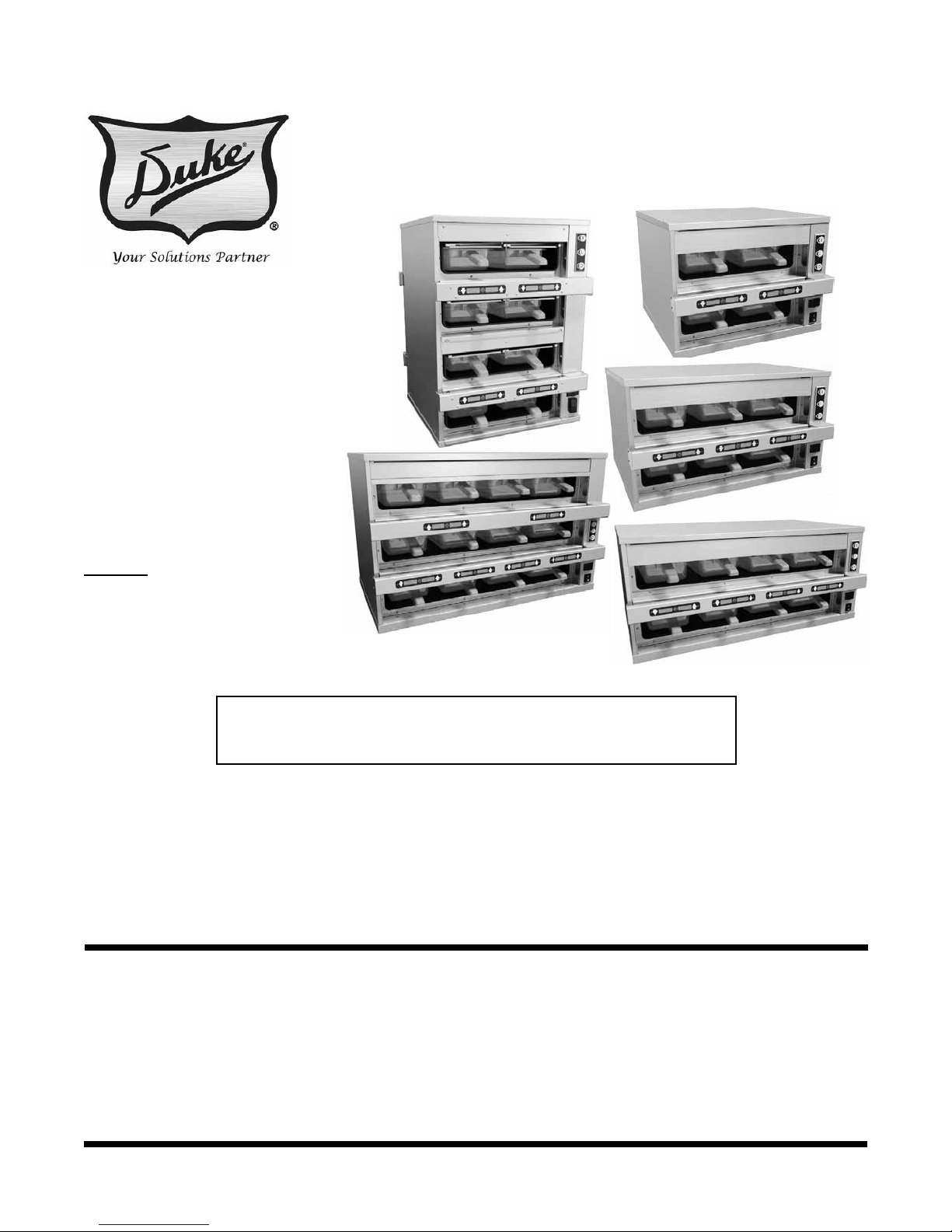
Infrared HeatSink (IRHS) Holding Unit Service Manual
3
SM-PH-IH-0003
TABLE OF CONTENTS
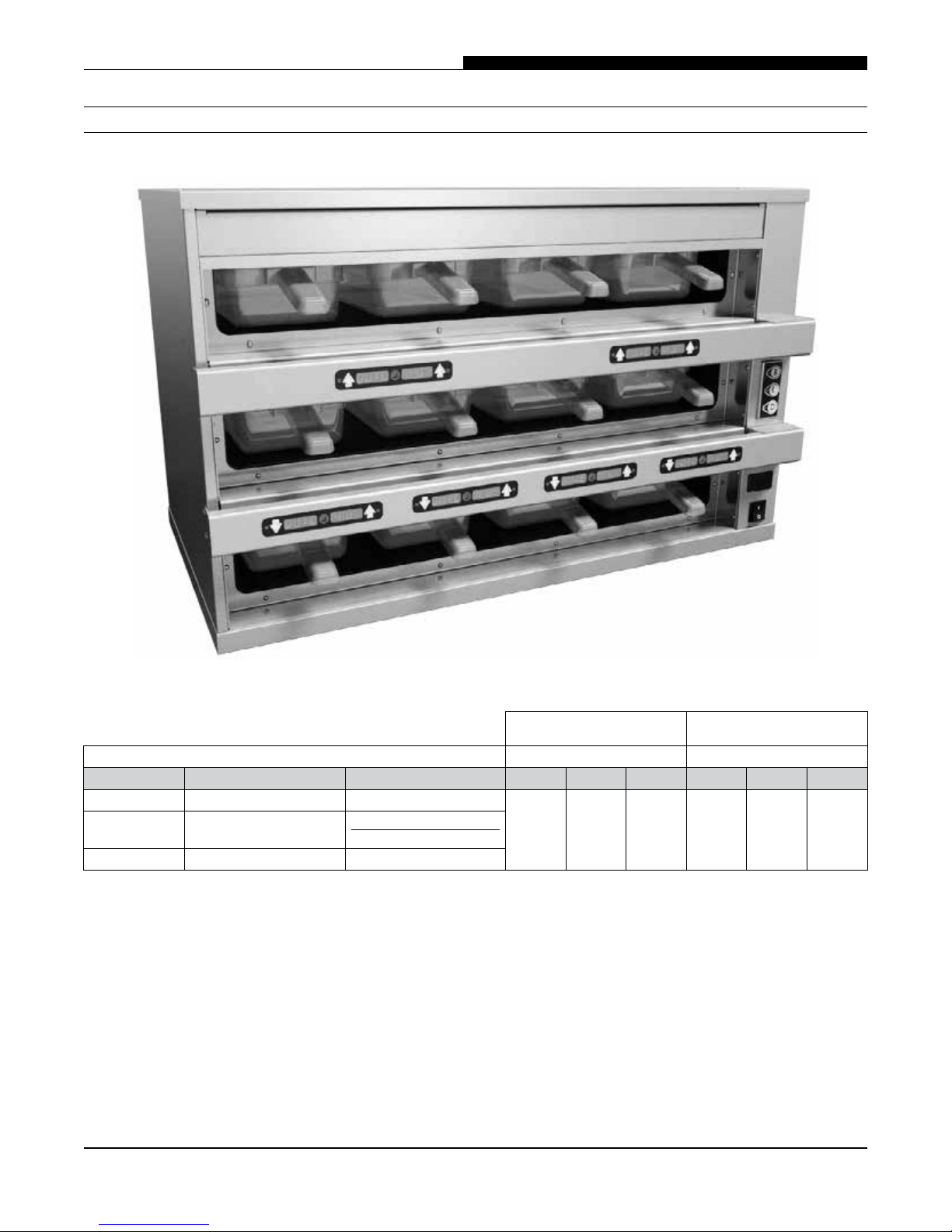
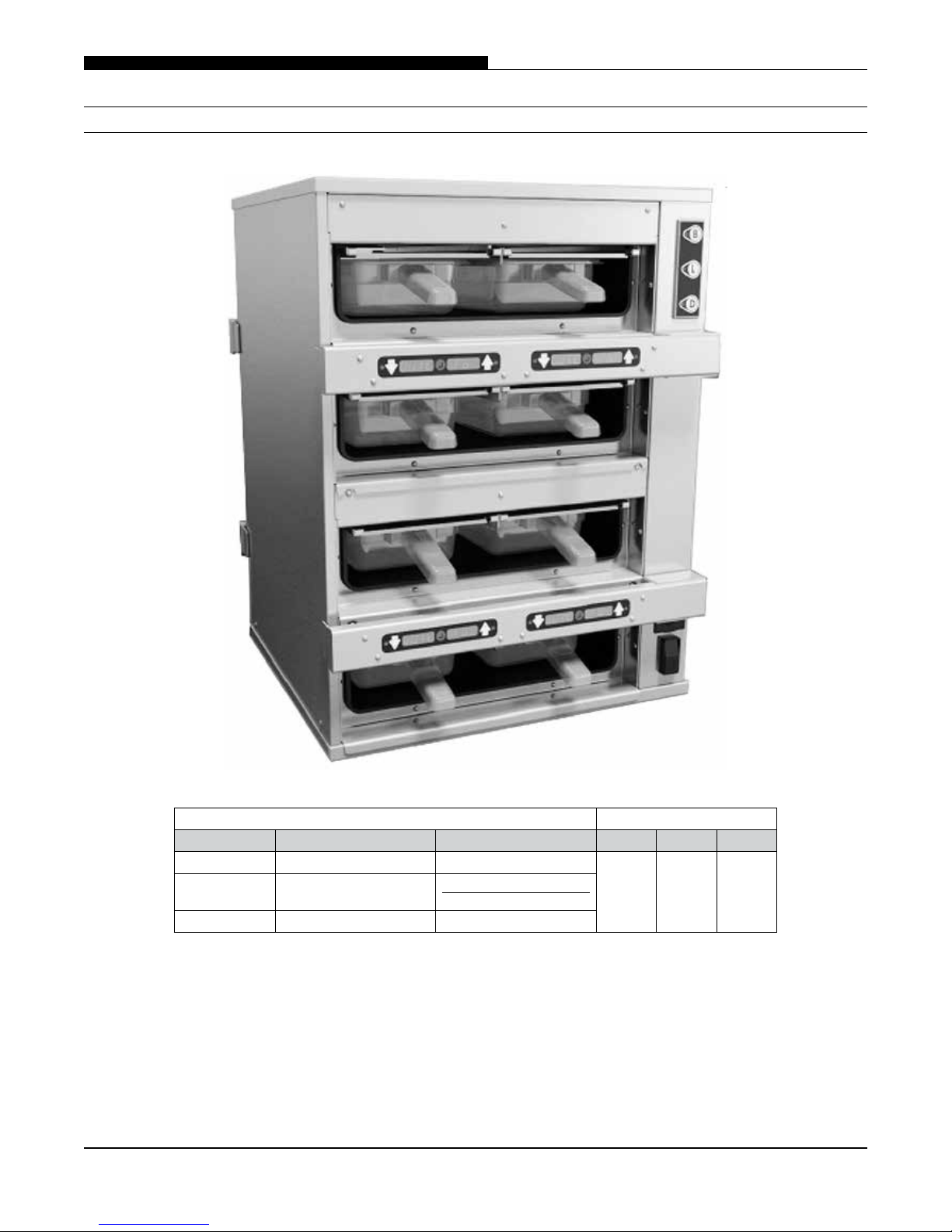
SPECIFICATIONS........................................................................................................................................ 5
IRHS22 .............................................................................................................................................. 5
IRHS23 .............................................................................................................................................. 6
IRHS24 .............................................................................................................................................. 7
IRHS34 .............................................................................................................................................. 8
IRHS42 .............................................................................................................................................. 9
REMOVALANDREPLACEMENTOFPARTS..............................................................................................10
EQUIPMENTUSEDINTHESEINSTRUCTIONS...................................................................................10
ELECTRICALLOCKOUT/TAGOUTPROCEDURE...................................................................................10
ESDWRISTSTRAP............................................................................................................................. 11
DECKASSEMBLYCOMPONENTS.......................................................................................................12
MENUBARS..............................................................................................................................12
KEYPADDISPLAYS....................................................................................................................... 14
RTD(TEMPERATURE)SENSORS.................................................................................................16
HIGH LIMIT THERMOSTATS........................................................................................................18
HEAT ELEMENTS........................................................................................................................21
EMITTER(IRBULB)SOCKETS.....................................................................................................24
EMITTERS(IRBULBS).................................................................................................................27
CONTROLCOMPARTMENTCOMPONENTS–STANDALONE&KITCHENMINDERMODELS(only)...28
POWERSWITCH......................................................................................................................... 28
USBADAPTER............................................................................................................................28
DAYPARTSWITCH.......................................................................................................................29
RELAYS(SmartPowerModules)................................................................................................ 29
CONTROLLER............................................................................................................................. 30
TRANSFORMER..........................................................................................................................30
RTDBOARD................................................................................................................................31
FUSES AND FUSE HOLDER.........................................................................................................32
CONTROLCOMPARTMENTCOMPONENTS–KITCHENMINDERMODEL(only)...............................33
KITCHENMINDERMASTERBOARD(ifinstalled).......................................................................33
KITCHENMINDERADAPTERBOARD(ifinstalled)......................................................................34
MOUNTINGPLATE(ifinstalled).................................................................................................35
COUPLERS(ifinstalled)..............................................................................................................36
CONTROLCOMPARTMENTCOMPONENTS–VISORMODEL(only).................................................37
12VPOWERCONTROLBOARD.................................................................................................37
POWERCONTROLBOARD–ACM..............................................................................................38
POWERCONTROLBOARD–103M............................................................................................39
POWERCONTROLBOARD–TRIACDRIVE.................................................................................40
FUSE HOLDER AND FUSES.........................................................................................................41
11/18/2015