Eagle Heated Drawers User manual

Heated Drawer
OPERATING MANUAL AND INSTRUCTIONS
EG9986 Revised 05/12
Eagle Foodservice Equipment, Eagle MHC, SpecFAB®, and Retail Display are divisions of Eagle Group. ©2012 by the Eagle Group
• 100 Industrial Boulevard, Clayton, Delaware 19938-8903 U.S.A. • www.eaglegrp.com
• Phone: 302/653-3000 • (Foodservice/SpecFAB®) 800/ 1-8 0 • (MHC/Retail) 800/637-5100
• Fax: 302/653-2065
(c ntinued inside)
INSTRUCTION SHEET
#339333
This unit has been manufactured in accordance with Underwriters Laboratories and National Sanitation
Foundation standards, consult local electrical and sanitation codes for compliance. lease reference the
electrical specifications in this manual to insure that proper amperage and voltage is used for your application.
Built-in units must be installed in compliance with the NEC.
• To unpack the heated drawer, first remove the four 3⁄8˝ bolts, using a wrench, that secure the unit to the crate
located on the underside of the crating (freestanding units only).
• Carefully remove the crating from the unit so as to not cause damage.
• Remove all plastic wrap from the exterior of the unit.
• Remove any tape or adhesive that may be holding the drawers closed.
• Please remove any warranty or instruction information from the drawers prior to use and store in safe
location for future reference.
• Remember to properly sanitize and clean the unit before use.
*"%*!")$%+#&(+*+(((%
&%***!")*&(-*!*&(-('()%**",&( #/)+*!&(".)(,"%*("%-&+((*&
'(&($$"%*%%%('"()
INS ECT CONTENTS IMMEDIATELY AND FILE CLAIM WITH
DELIVERING CARRIER FOR ANY DAMAGE.
YOU ARE RES ONSIBLE FOR DAMAGE TO YOUR UNIT
IF RETURNED IM RO ERLY ACKED.

(*)")*
2

(*)")*
3

4
Remove any tape that may be holding the conduit to the unit before installing.
1Tape
Please read the information provided under Location before determining installation site.
2Location
Determine cutout sizes for your unit using the chart located below.
3Level
When the proper cutout has been made, a locking strip (not supplied by Eagle) must be permanently fixed to the lower front side
of the cabinet opening.
N te: Maintain a minimum clearance of 1˝ from the bottom of the cutout to floor.
4Locking Strip
Once the unit is installed into the opening, apply a bead of NSF-approved sealant around the drawer cabinet flanges and the location.
5In talling
Final connections must be made in accordance with a NEC listed junction box.
6Connection
Locate the unit in an area that is convenient for use. The location should be level to prevent the unit or it’s
contents from accidentally falling, and strong enough to support the weight of the unit and it’s contents.
a
For safe and proper operation, the unit must be located a reasonable distance from combustible walls and
materials. If safe distances are not maintained discoloration or combustion could occur.
b
Cut ut Sizes f r Built-In Drawer Warmers
Model Height Width Depth
DWW-1BI-120 or 240 107⁄8˝ 293⁄4˝ 233⁄8˝
DWW-2BI-120 or 240 213⁄4˝ 293⁄4˝ 233⁄8˝
DWW-3BI-120 or 240 325⁄8˝ 293⁄4˝ 233⁄8˝
DWN-1BI-120 or 240 107⁄8˝ 213⁄4˝ 265⁄8˝
DWN-2BI-120 or 240 213⁄4˝ 213⁄4˝ 265⁄8˝
DWN-3BI-120 or 240 325⁄8˝ 213⁄4˝ 265⁄8˝
()*%"% %"*)
+"#*%%"*)
LEGS MUST BE INSTALLED RIOR TO THE O ERATION OF THE UNIT.
TO AVOID DAMAGE, DO NOT LAY UNIT ON ITS FRONT OR BACK SIDE.
Install the legs into the bottom of the unit by threading them into the nut inserts and tightening securely.
1Leg
Locate the unit in a desired area within reach of an appropriately sized electrical outlet. Consult electrical chart.
2Outlet
Place unit on a flat, even surface and check that the unit is level both left-to-right and front-to-back. Adjust feet as
needed for a level installation.
3Level

5
#+ &%" +(*"&%)
+"#*%%"*)
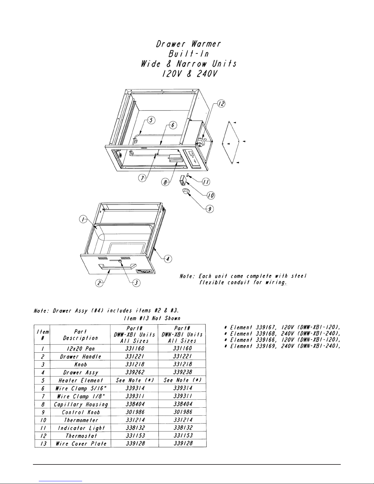
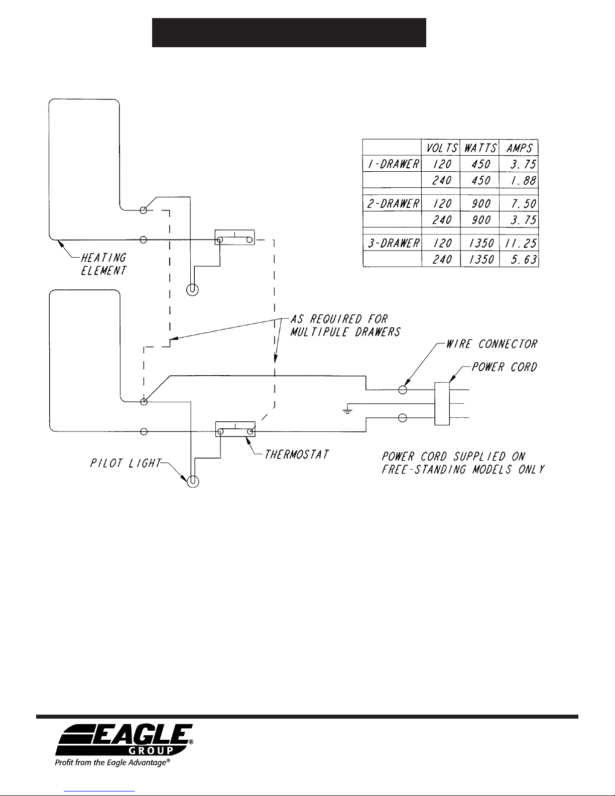
All built-in units are supplied with factory installed flexible steel conduit and applicable wiring.
()*%"% %"*)
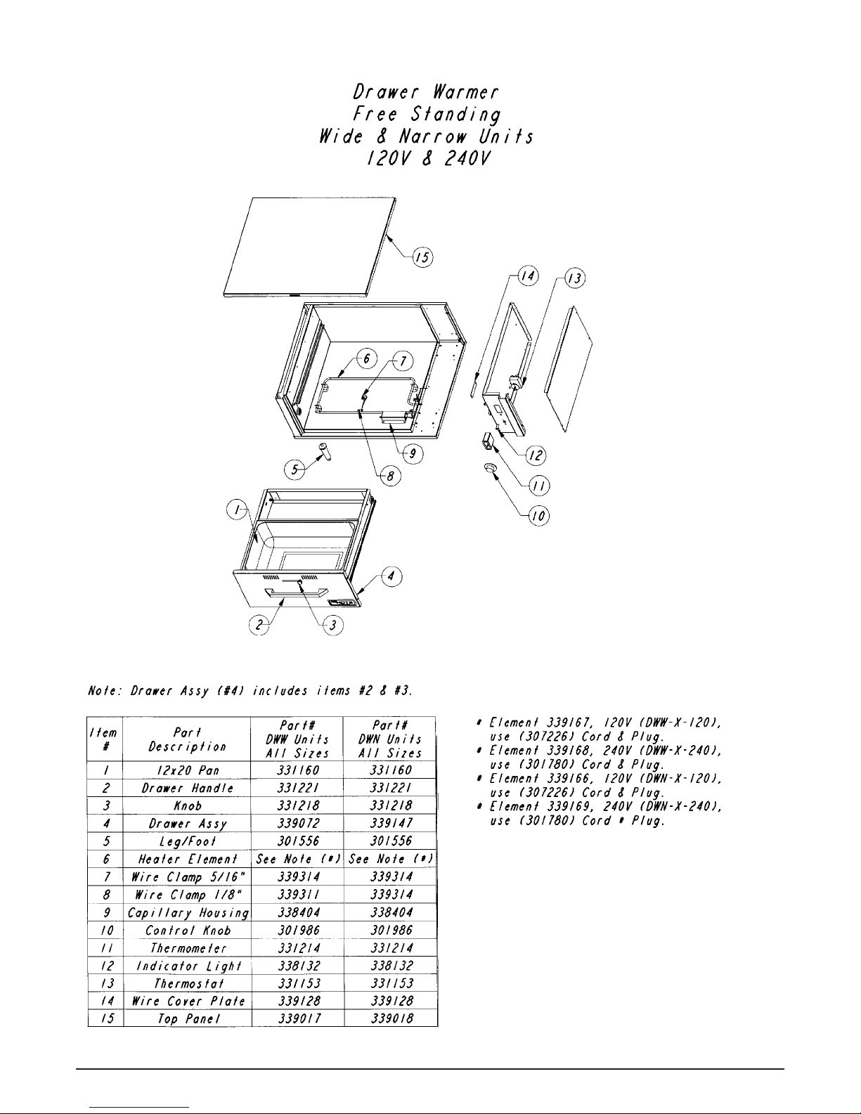
All freestanding units are factory supplied with a cord and plug. Please check to make sure that the plug matches the receptacle.
1) 120V units supplied with a NEMA 5-15P plug configurations.
2) 2 0V units supplied with a NEMA 6-15P plug configurations.
FOR FREESTANDING UNITS, PLUG UNIT ONLY INTO A RECEPTACLE OF COMPATIBLE VOLTAGE AND PLUG
CONFIGURATION. IF THE APPROPRIATE RECEPTACLE IS NOT AVAILABLE, CONTACT A CERTIFIED ELECTRICIAN
TO INSTALL THE CORRECT OUTLET. SEE “ELECTRICAL RATING CHART” BELOW.
Model Watts Amps Plug Length Depth Height
DWW-1-120 450 3.8 NEMA 5-15 29˝ 231⁄4˝ 161⁄4˝
DWW-1-240 450 1.9 NEMA 6-15 29˝ 231⁄4˝ 161⁄4˝
DWW-2-120 900 7.5 NEMA 5-15 29˝ 231⁄4˝ 265⁄8˝
DWW-2-240 900 3.8 NEMA 6-15 29˝ 231⁄4˝ 265⁄8˝
DWW-3-120 1350 11.3 NEMA 5-15 29˝ 231⁄4˝ 37˝
DWW-3-240 1350 5.6 NEMA 6-15 29˝ 231⁄4˝ 37˝
DWN-1-120 450 3.8 NEMA 5-15 21˝ 273⁄4˝ 161⁄4˝
DWN-1-240 450 1.9 NEMA 6-15 21˝ 273⁄4˝ 161⁄4˝
DWN-2-120 900 7.5 NEMA 5-15 21˝ 273⁄4˝ 265⁄8˝
DWN-2-240 900 3.8 NEMA 6-15 21˝ 273⁄4˝ 265⁄8˝
DWN-3-120 1350 11.3 NEMA 5-15 21˝ 273⁄4˝ 37˝
DWN-3-240 1350 5.6 NEMA 6-15 21˝ 273⁄4˝ 37˝
DWW-1BI-120 450 3.8 Conduit 31˝ 231⁄4˝ 121⁄4˝
DWW-1BI-240 450 1.9 Conduit 31˝ 231⁄4˝ 121⁄4˝
DWW-2BI-120 900 7.5 Conduit 31˝ 231⁄4˝ 231⁄8˝
DWW-2BI-240 900 3.8 Conduit 31˝ 231⁄4˝ 231⁄8˝
DWW-3BI-120 1350 11.3 Conduit 31˝ 231⁄4˝ 34˝
DWW-3BI-240 1350 5.6 Conduit 31˝ 231⁄4˝ 34˝
DWN-1BI-120 450 3.8 Conduit 23˝ 263⁄4˝ 121⁄4˝
DWN-1BI-240 450 1.9 Conduit 23˝ 263⁄4˝ 121⁄4˝
DWN-2BI-120 900 7.5 Conduit 23˝ 263⁄4˝ 231⁄8˝
DWN-2BI-240 900 3.8 Conduit 23˝ 263⁄4˝ 231⁄8˝
DWN-3BI-120 1350 11.3 Conduit 23˝ 263⁄4˝ 34˝
DWN-3BI-240 1350 5.6 Conduit 23˝ 263⁄4˝ 34˝
Electrical Rating Chart

6
On freestanding models, plug unit into an electrical outlet of the correct voltage, size and plug configuration.
1Plug
To turn the power on, turn the thermostat control to the desired temperature. See “Food Holding Guide” below for
recommended settings.
2Power
Allow the unit 15-20 minutes to reach operating temperature. Moist applications may require additional preheat time.
3Pre-heat
Referring to “Food Holding Guide” below, adjust the drawer vents for desired humidity by loosening front drawer knob to unlock
the vent and slide the vent to desired location. Opening the vent all the way allows maximum moisture to escape.
4Vent
F d H lding Guide
Product Rec. Storage Temp. Heat Type Vent Control Capacity
Rolls, Hard 160-185˚F (71-85˚C) Dry closed 6-8 dz
Rolls, Soft 150-175˚F (66-79˚C) Moist open-half 6-8 dz
Vegetables 175-185˚F (66-85˚C) Moist open-half 3-31⁄2dz potatoes
Meat, oultry 165-185˚F (74-85˚C) Dry closed 25-30 lbs. ribs
Fish 165-185˚F (74-85˚C Moist open
Casseroles 150-175˚F (66-79˚C) Dry closed
ies, Desserts 160-185˚F (71-85˚C Dry closed

7
(%"%*%%
To avoid injury, turn the power off and allow unit to cool before cleaning or performing maintenance.
On freestanding units, unplug the electrical cord and/or turn off circuit breaker.
To preserve the finish of the drawer warmer, it is recommended that the surface be wiped daily with a damp
cloth. Food pans should be removed and washed. Stubborn stains may be removed with a non-abrasive
cleaner. Hard to reach areas should be cleaned with a small brush and mild soap.
Rem ving Lime and Mineral Dep sits
Note: If the water used has an excessive amount of lime or mineral content, use the following instructions
for periodic cleaning and de-liming of the water pan.
1. Turn off the power. On freestanding units, unplug the cord from the power source.
2. After the unit has cooled down, remove the water pan.
3. Fill the water pan with a mixture of water and de-limer. Allow the pan to stand with the mixture for the
recommended period of time. The time required will depend on the solution used and the amount of
deposits in the pan. Check de-limer manufacturer for specific directions.
. After the de-liming period, drain the solution from the pan.
5. Continue to fill and rinse the pan with water only, until the pan becomes clean.
6. Install the pan into the unit. On freestanding units, plug the power cord into the receptacle and fill the pan
as usual.
Abrasive cleaners could scratch the finish of the drawer warmer.

Eagle Foodservice Equipment, Eagle MHC, SpecFAB®, and Retail Display are divisions of Eagle Group. ©2012 by the Eagle Group
• 100 Industrial Boulevard, Clayton, Delaware 19938-8903 U.S.A. • www.eaglegrp.com
• Phone: 302/653-3000 • (Foodservice/SpecFAB®) 800/ 1-8 0 • (MHC/Retail) 800/637-5100
• Fax: 302/653-2065
"("% " ($
This manual suits for next models
4
Table of contents
Popular Heated Shelf manuals by other brands

FPG
FPG INLINE 3000S Series product manual

Hatco
Hatco HBG-3018 Installation and operating manual

Vollrath
Vollrath FC-4HS-48120-SSR installation instructions

Hatco
Hatco Glo-Ray GRSB-24-F Specifications

Hatco
Hatco HGSM Series Installation and operating manual

Hatco
Hatco Glo-Ray GRSR-19 Replacement parts list