1. Preparation
Planning and preparation of ceiling openings to
is important; openings should be uniform,
straight and free from all obstructions prior to
panel installation. It is essential to co-ordinate
all installation works with other trades.
2. Layout
Panel runs should be set out on a layout plan.
Radiant panels should be concentrated in areas
of highest heat loss i.e. around the outside
perimeter of the room, particularly, near
windows. This will counteract disproportionately
high heat losses. Single or dual circuit runs
should be considered- see Water flow rates
and Hydraulic Resistances below.
4. Maximum mounting height
There is no maximum mounting height for
Evo-Lite. However, when mounting heights
exceed 4m, the heat load should be adjusted to
allow additional losses of radiant heat incident
on walls, and stratification of air which absorbs
some heat by convection.
5. Minimum mounting height
There is no minimum mounting height for
Evo-Lite. For comfort and safety the following
rule of thumb can be applied:-
All Styles
LTHW - minimum mounting height 2.4m
MTHW - minimum mounting height 3.0m
Contact Dunham-Bush for further information
on mounting heights and comfort conditions.
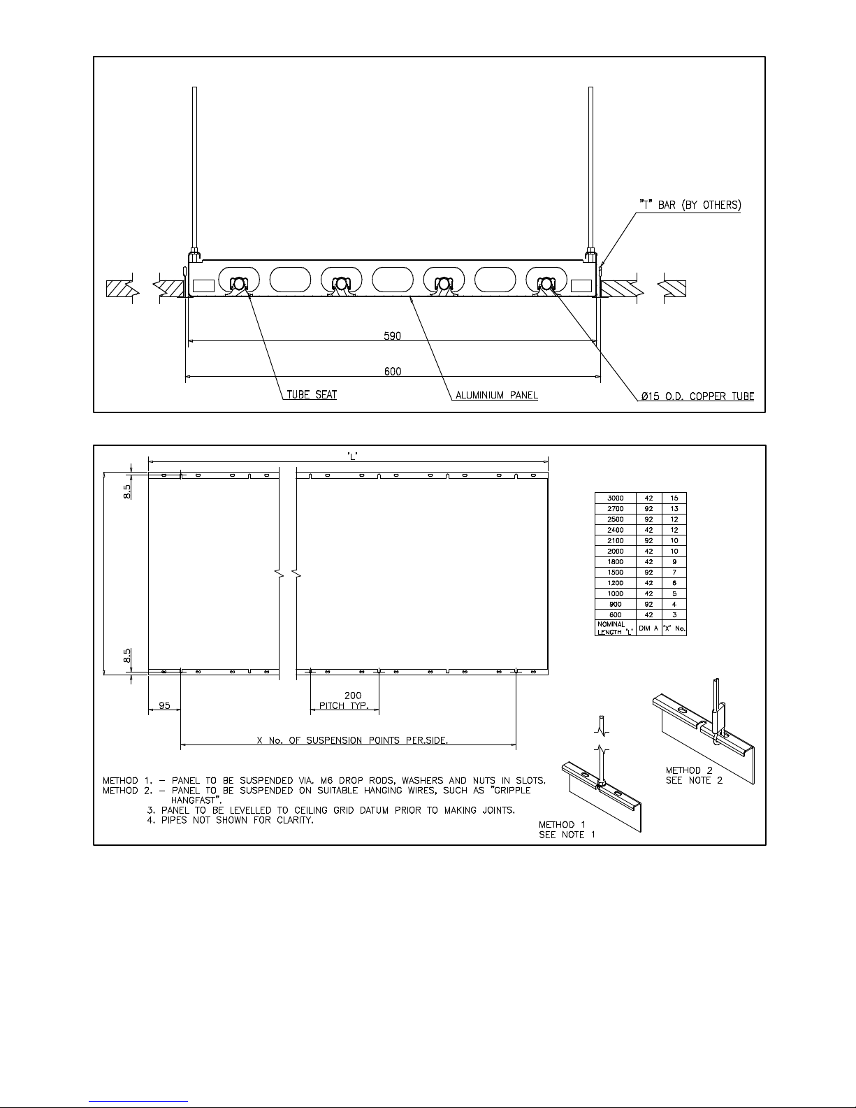
5. Expansion joints
Expansion joints should be fitted every 6m in a
straight panel run.
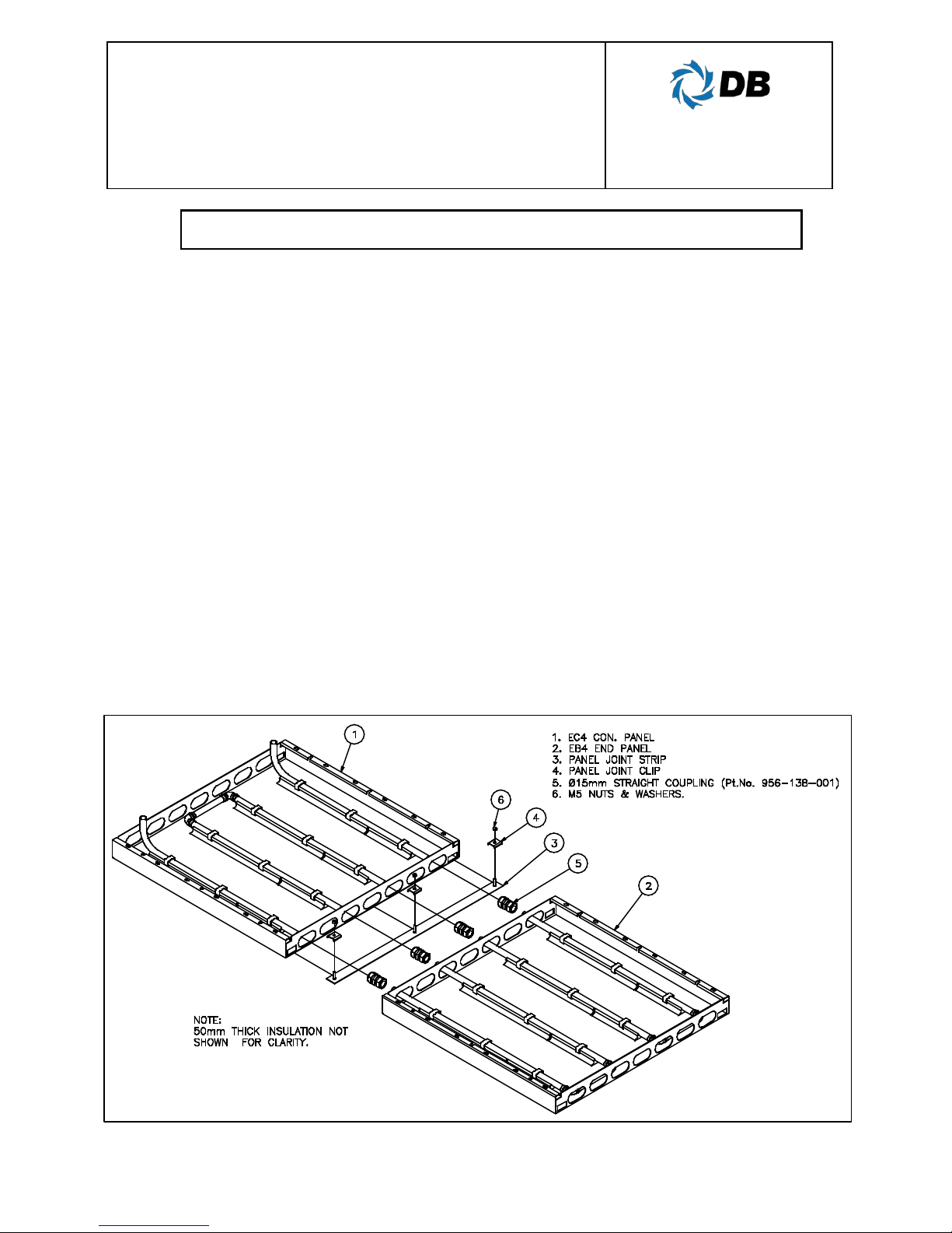
6. Panel runs
Refer to Diagram 2 for typical arrangements in
a panel run. Dunham-Bush will prepare
complete baseboard layout drawings for
approval, which can be used to co-ordinate
materials and installation on site.
7. Water flow rates
To ensure rated heat outputs are achieved,
water velocity in the tube should be such the
water flow is turbulent. This maximises heat-
transfer from the water, through the tube and to
the radiating surface. Water flow rates should
also be limited to inhibit noise and erosion and
high pressure drops. Water velocities should
ideally be between 0.3 - 1.0m/s.
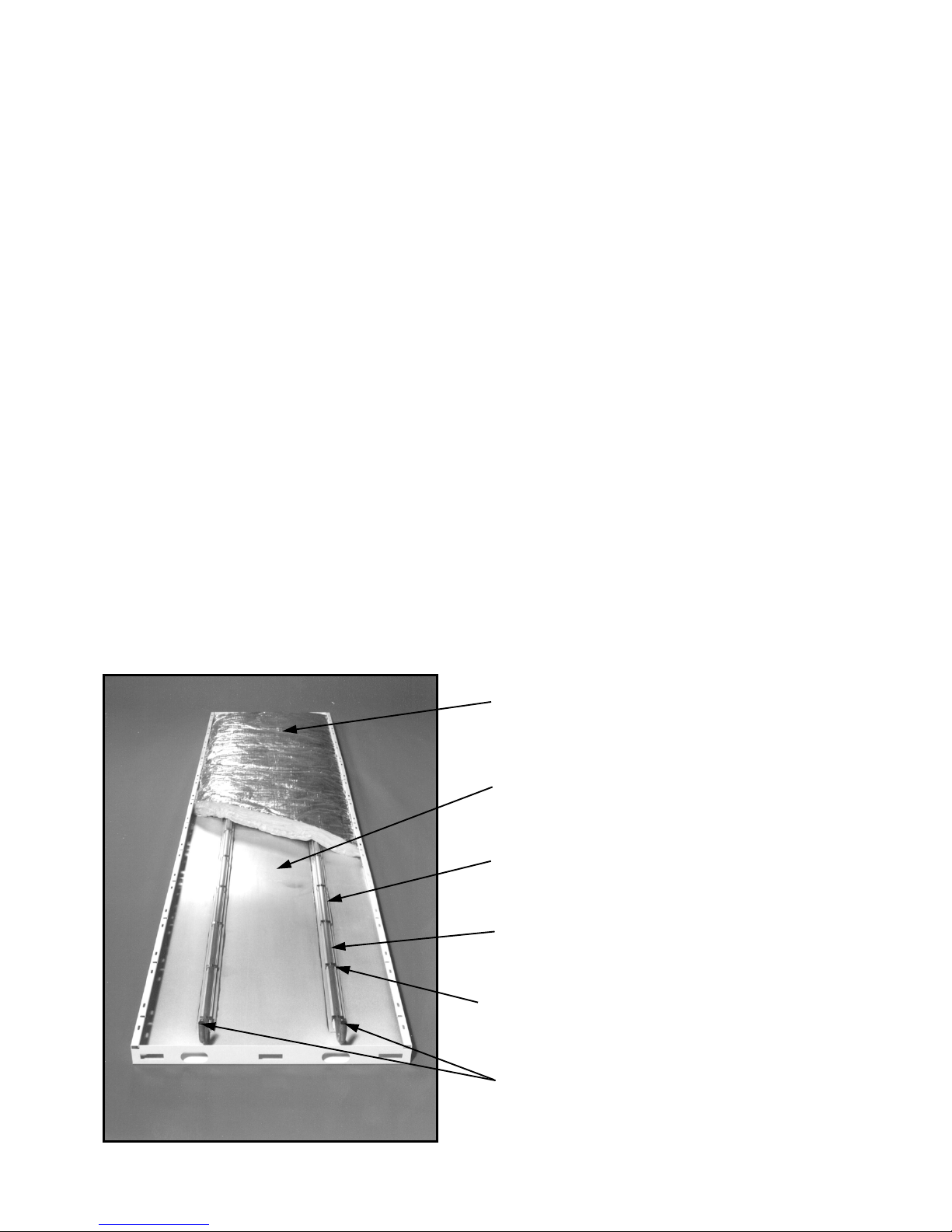
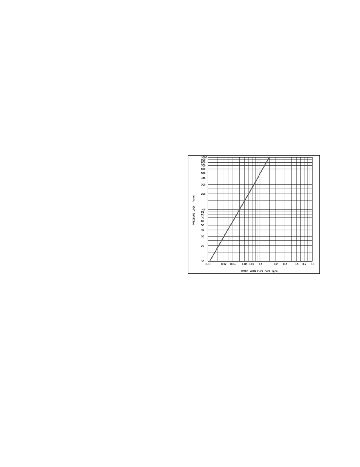
8. Hydraulic resistances
Evo-Lite utilises 15mm OD copper tube to
transport hot water.To calculate the total
pressure drop, determine the water flow rate :-
Water flow = Q
rate (kg/s) Cpx ΔT
Q = total heat output (kW)
Cp= specific heat capacity of water
(kJ/kgK); approx. 4.187
ΔT = water temperature drop
Obtain the hydraulic resistance from the graph
below. Note that the water flow rate should be
halved if dual circuit panel runs are used (i.e.
type EH and EJ panels). N.B. circuit length
applies for one circuit only
9. Applications
Evo-Lite Style CG is designed to fit into
conventional 'lay-in' tile ceiling grids; panel
dimensions have been optimised so that panel
edges are concealed by standard ceiling grid
T-bars - typically 15mm or 24mm. For other
types of ceiling, Style FS or Style CS panels
may be more appropriate. Style WS panels
are designed for vertical wall surface
applications. Contact Dunham-Bush for details.
Page 7 of 8