Duomo SGF 104 User manual

SGF 104 Oxygen Sensor
The SGF104 has been introduced by Duomo at the
requestofarchitectsandconsultantstoprovideamore
architecturally discrete enclosure without compromi-
sing the sensitivity of detection. Other sensors within
theSGF100rangesenseNaturalGas,CarbonMonoxide,
Freon, Hydrogen Sulphide, Hydrogen and LPG.
The SGF104 is used to monitor levels of oxygen in
locations such as:
• Research & Teaching Laboratories,
• Food & Manufacturing,
• Electronics assembly clean rooms.
Where a risk, for example, of Nitrogen (or any inhert
gas) leaking may reduce oxygen content within an
enclosed environment.
Installation and user guide
Firmware Version 1.0
• Oxygen sensor
• 4-20mA output
• Senses depletion or Excess O2
• Compatible with Duomo controllers*
• Architecturally discrete Gas sensor
• Ceiling or wall mounted
• Status indication lights
• Conforms to EN50104 and EN50270
• 12 to 24V DC supply
• Relay output 1A @ 30V DC
• IP64 Protective rating
Applications
Features
i
The SGF104 senses either a reduction or an increase in
levels of of oxygen. It provides a signal proportional to
the levels of oxygen to either a Duomo central control
from the GS or BX range or directly to Building Mana-
gement Systems.
Operation
The self-calibration facility allows the probe to adapt
in dicult environments and variable temperatures
helping to avoid false alarms.
By connecting a datalogging and diagnostic tool
(Duomo TS1007) to the sensor It is possible to read
backsensorhistoryandotherindividualsensorspecic
information, such as:
• Sensor serial number,
• Date of manufacture,
• Number of power ups,
• Number of alarms,
• Number of days of anticipated
sensor life remaining
The SGF104 Oxygen Depletion sensor has a range of
0-25% Oxygen. The system is normally set to give a
rst stage warning alarm at 19.0% Oxygen, and then a
secondstage full alarm at17.0%.This enables action to
be taken before an evacuation is required and evacua-
tion before a dangerous situation arises. Excess Oxyen
levels can be monitored and an alarm relay activated
at 22.5 or 23.5%.
Before connecting the unit careful reading of instruction booklet is recommended,
and it is kept in a safe place for future reference. Furthermore, the correct electrical
connections according to the enclosed drawings, complying with instructions.

Page 2
Important:
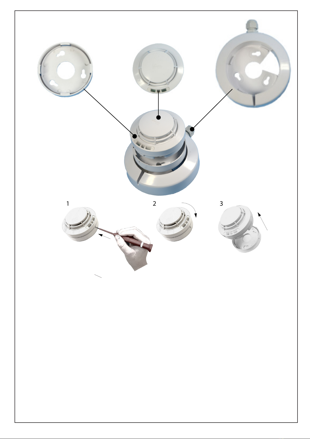
The installation of the SGF104, commissioning, service and removal must be carried out by
authorized and/or specialized personnel. During installation the sensor enclosure must not be
pierced to do so will compromise the protective rating protection.
The installation of the detector does not exempt the user from compliance with all regulations
concerning the characteristics, installation and use of associated equipment. The ventilation
of the spaces and, for example, the removal of combustion products are described in the UNI
norms such as ART. 3 LAW 1083 / 71 and relevant legal provisions.
Do not allow the sensor to become wet.
The probe can be seriously damaged when immersed in water. Remember that the probe has
an IP64 protection degree.
Handle with care
Heavy knocks or falls during transportation or installation can damage the sensor.
Avoid abrupt temperature uctuations.
Sudden temperature variations can cause condensation and the probe could work poorly. Tem-
perature compenstation is tted to this sensor but rapid changes will still aect the functionality.
Cleaning Never clean the device with chemical products. Absolutely avoid using any cloth dip-
ped in thinners, alcohol and chemical detergents. The outer enclosure should only be cleaned
using a damp cloth.
Power supply ....................................................................................................................... 12÷24 VDC ± 10%
Power demand ...................................................................................... 110 mA in alarm Max @ 13,8 VDC
Relay switching alarm ......................................................................................................... 1 A 30VDC SELV
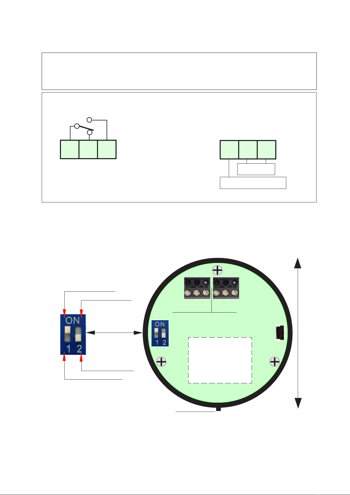
Selection of positive safety........................................................................................ Selectable by switch
Type of gas detected: Oxygen
Integratedsensoraccordingtothetypeofgas...........................................................Opticaluorescence
Operating range of the sensing element ..........................................................................0 - 25 % of O2
Operating range selectable by switch ....................... 19.5 or 18.5% of O2 (depletion), 22.5, 23.5%
of O2 (Excess) Note1
Detector accuracy ...............................................................................................................................+/- 1% FS
Long term shift in clean air ...................................................................................................... < 3% of L.E.L.
Auto zero procedure .................................................................... Included in the software algorithms
ResponseTime ............................................................................................................................................... < 10”
Functioning humidity .............................................................................................. 0-90% not condensed
Functioning temperature ..................................................................................................... -30°C to +60°C
Control units usable directly.................................................................................................... BX308, BX316
Control units usable with adapter code yy.............. BX444-Mc, BX449F, GS100M, BX180, BX280,
BX150, GS300M
Cable diameter for connecting probe - Note2............................................................ 1 mm for 100 mt
Section shielded cable transmission distance up to 500 meters .............................x0,75mm2CSA
Installation...................................................................................................................ceilingorwallmounted
Anti-tamper protection ..................................................................................................................... included
Enclosure.................................................................................................... ABS self-extinguishingVDE0471
External degree of protection........................ IP64
Overall dimensions ...........................................Diameter 90 mm, Depth 45mm
Electromagnetic compatibility Reference Norms ... EN 50270
Note1.
On SGF104 the trigger levels are dependant on the position of the DIP switch 2 selection.
They are respectively 19.5% (depletion) and 22,5% (excess) - DIP2 in OFF position - or 18.5%
(depletion) and 23,5% (excess) - DIP2 in ON position.
Note2.
Connection: The sensor cable must not be installed together with the power cables. If this is
unavoidable it is imperative otherwise, make sure to use a shielded cable.
Technical Specication

Page 3
Backplate supplied
with SGF Series Sensors
Assembly of three parts of the SGF’s Series sensor
OPTIONAL Socket connection with
cable gland for external mounting
on demand Art. ZSGF100
Socket assembly.
Place the probe as in the drawing,
and rotate in clockwise direction
WARNING! Actions to be taken in case of alarm
Oxygen “O” is an odorless gas, colourless, slightly heavier than air (specific gravity of 1.1). The
air we breathe consists of 20,95% Oxygen.
Oxygen is not in itself a ammable gas but being a strong oxidant, it reacts with combustible and
reducing materials causing risks of re and explosion because it enhances the combustion.
If the concentration of the O in air drops below 19.5%, it is considered decient for health of pe-
ople, then if the concentration drops below 16%, it causes breathing problems until to cause the
asphyixia and below 6%, it causes the immediate death.
Oxygen deciency can be caused by the increase in the air of other gases (toxic and / or ammable),
and also from the leaks of inert gases (nitrogen, helium, argon, etc.).
At high concentrations, over 24%, O is irritating to the respiratory tract and can cause eects on
the central nervous system, eyes and the lungs.
In either case, open doors and windows to increase the ventilation. If the alarm continues and the
cause can not be identied leave the bulding and, from the outside, to call emergency services.

Connections and P.C.B. Layout
Page 4
Data connection tool TS007
Connecting the tester TS1007 it is possible to sensor history and print
the test report. This report will show the information listed below.
Legend of display
Display“ADC”shows the decimal value of the capsule and the type of “GAS”
Displays the type of sensor,
Displays the serial number,
Displays the manufacture date,
Displays the remaining days at the end of the operating cycle.
Displays how many times the probe has been turned on.
Displays how many times is gone into alarm
Displays how many corrections have been done
Displays the operating range if at 20 or at 100% of LEL
Displays the percentage of dispersed gas
Displays if the probe is in fault
Indicates if you want to print the ticket
Indicates if you want to reset the probe to the data factory.
Asks to save the modied data
Indicates when the battery is low
1
ADC 80 16 (125 145)
probe sgF104
sn 24ad12
date 15 2014
DaY 2190
cy 5
al 15
drift 12
range 20
lel 20% (fault)
print
tar
new save
low bat
unlock
pivot
C NC NO
R - +
Gas probe SGF104
S.N. ED567D
Year 12/2015
Batch: SGF104/001
Gas : Oxygen
Power supply 12/27VDC
Absorption 110 mA
Relay 1A 30V SELV
Signal 4 - 20 mA
USB
Detection data memory through
USB port
Connect the sensor to the TS1007
and read the data transmitted.
Switch 1 - Selection of positive
safety
Switch 2 - Operating range.
Green: Operating
Red: Flashing: detecting gas or Steady: alarm threshold
exceeded.
Yellow: Fault
Operating LED
Sensor Status indication
Typical print out

Page 5
The positioning of the sensor is an important factor for the correct function of the gas detection
control unit.
In order to obtain the best results and minimize the probabilities of false alarms, we recommend
following this diagram and to keep in mind the following general rules.
The probe should be placed at a height of about 1.60 cm from the ground, if the height of the room
is higher than 2.8m it is recommended to install it at an average height between ceiling and oor.
The sensor should not be tted where it is likely to be aected by smoke, vapour, etc. as they could
distort indicated measurements.
The sensor must be placed away from sources of heat, suction fans, ventilation fans.
The general test should be performed by issuing gas from a pre-calibrated bottle within the
percentages marked on the bottle information label. Important: This test must be carried out
at least once a year or more frequently if required based on a risk assesment of the setting.
Positioning of the Sensor
Unlock hole
Note !
When is mounted on the wall, the orientation is obligatory, See pictures below.
Gas Testing
Unlock hole
Test Gas Concentrations for testing the SGF104 Oxygen sensor:
DEFICIENCY OXYGEN 18% vol
OXYGEN 20,95 vol
EXCESS OXYGEN 24% vol
Important - Test with calibrated gas only!
Ceiling mounted
X

Page 6
Current-Voltage Conversion Graph with 220 Ohm Load Resistance
0 4 5 10 15 20
VDC
mA
0,88 1,1 2,2 3,3 4,4
Linear +/-5%
Sensor Output relative to Oxygen content in Air - % vol.
If the device does not start up.
Check that the 12/24 Vdc power is present, and that positive and negative polarity has not been inverted.
If the Fault LED lights up - If the fault signal reaches the control unit connected to the sensor.
Check that the cables are connected according to the drawing, and that the wire isolation sheath has not
been pinched.
Check the voltage between terminals 1-2. It must be higher than 10,80 Vdc and lesser than 26,4 Vdc.
Check the voltage between terminals 2-3. It must be a minimum of 0.8 Vdc to a maximum of 1.1 Vdc.
Important Note:
These measurement should be perfor-
med in clean/fresh air.
Moreover, this test must be perfor-
med only with the probe connected
to a control unit, or with a 220 Ohm
resistance installed between terminal
2 and terminal 3.
Troubleshooting before calling a technician
Power supply
12÷24 VDC
Linear ouput 4-20 mA
3 2 1
R
0 18,5 19,5 20,9 22,5 23,5 25.0 %vol
Oxygen
Normal level
Pre-alarm
Pre-alarm
Deciency
Oxygen alarm
Excess
Oxygen alarm
20
19.4
18.4
17.4
16.5
15.8
4
0
mA
-+
0
1
3
2
1,1
V.
Voltmeter

Page 7
WARNING
Before connecting to the power, ensure the voltage is correct. Carefully follow the instructions and
the connections according to local regulations.
For optimum performance connect using Screened cable earthed at one end.
Avoid running sensor cable close to any power cabling.
R - + C NC NO
J3 J5
Unlock
Pivot
Gas probe SGF100
S.N. ED567D
Year 06/2015
Batch: SGF104/001
Gas Oxygen
Power supply 12/24VDC
Absorption 110 mA
Relay 1A 30V SELV
Signal 4 - 20 mA
USB
data detection
Operating range 20%
Positive safety OFF
Positive safety ON
Operating range 100%
When it is mounted on the wall
UP
DOWN
Power supply Relay
Relay max 1A Power supply
30 VDC SELV detection 4/20 mA
Note!
The relay is voltage free.
Contact capacity 1A 30VDC resistive. SELV
Linear output 4-20 mA
Power supply
12÷24 V.
3 2 1
R-+
3 2 1
Electrical Connections

INSURANCE. This device is insured by the SOCIETÀ REALE MUTUA for the PRODUCT’S GENERAL LIABI-
LITY up to a maximum of 1,500,000.00 EURO against damages caused by the device in case of failures
in functioning.
WARRANTY. The warranty term is 3 years from manufacturing date, in agreement with the following
conditions. The components acknowledged as faulty will be replaced free of charge, excluding the re-
placement of plastic or aluminium cases, bags, packing, batteries and technical reports.
The device must arrive free of shipment charges to DUOMO Ltd
Defects caused by unauthorized personnel tampering, incorrect installation and negligence resulting
from phenomena outside normal functioning shall be excluded from the warranty.
DUOMO Ltd is not liable for possible damage, direct or indirect, to people, animals, or things; from
Made in Italy
IP64
DISPOSAL OF OLD ELECTRICAL & ELECTRONIC EQUIPMENT.
Thissymbolontheproductoritspackagingtoindicatesthatthisproductshallnotbetreatedashousehold
waste. Instead, it shall be handed over to the applicable collection point for the recycling of electrical
and electronic equipment, such as for example:
- sales points, in case you buy a new and similar product
- local collection points (waste collection center, local recycling center, etc...).
By ensuring this product is disposed of correctly, you will help prevent potential negative consequence
for the environment and human health, which could otherwise be caused by inappropriate waste han-
dling of this product.The recycling of materials will help to conserve natural resources. For more detailed
information about recycling of this product, please contact your local city oce, your household waste
disposal service or the shop where you purchased the product.
Important Note: In some countries of the European Union, the product is not included in the eld of
application of the National Law that applies the European Directive 2002/96/EC and therefore these
countries have no obligation to carry out a separate collection at the “end of life”of the product.
In accordance with its continuous development policy, DUOMO (UK) Ltd reserves the right to modify its
products and datasheets without notice.
5 The Furlong Berry Hill Industrial Estate Droitwich, Worcestershire. WR9-9AH
Table of contents
Other Duomo Accessories manuals