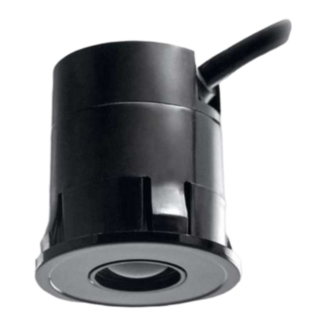
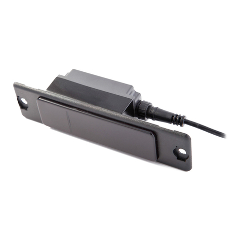
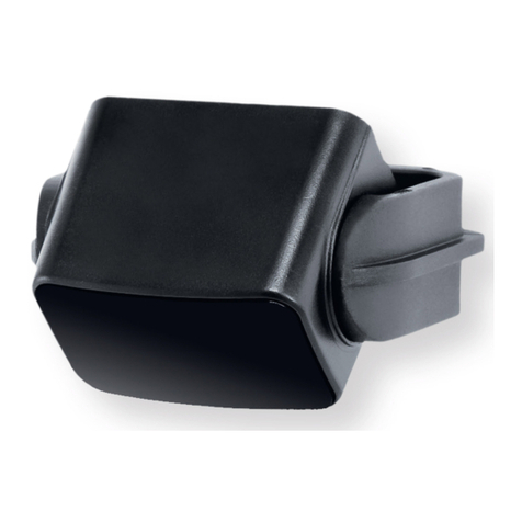
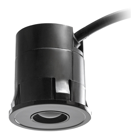
Cedes ELS 300 User manual

CEDES
© CEDES Version 2.0 / 17th October 2016 Part No. 105 742
ELS 300
Safety trough-beam sensor
Safety Category 2 in combination with
a supervising control unit
English
Deutsch
Français
Español
Polski
EN 61496-2:2013
EN ISO 13849-1:2015
IMPORTANT NOTE
FOLLOW THE INSTRUCTIONS GIVEN IN THIS MANUAL CAREFULLY. FAILURE TO DO
SO MAY CAUSE CUSTOMER COMPLAINTS AND SERIOUS CALLBACKS. KEEP
INSTRUCTION MANUAL ON SITE.
Installation and Operation Manual
Bedienungsanleitung
Mode d’emploi
Instrucciones de montaje y uso
Instrukcja montażu i obsługi

ELS 300 Installation and operation manual
2 www.cedes.com © CEDES/October 2016
IMPORTANT INFORMATION
ELS 300 SHOULD ONLY BE INSTALLED BY AUTHORIZED AND FULLY TRAINED
PERSONNEL! ELS 300 IS ONLY A SAFETY PROTECTION DEVICE IF ALL
INSTRUCTIONS IN THIS MANUAL AND IN THE RELATED DOCUMENTS, ARE
CAREFULLY FOLLOWED AND FULLY COMPLIED WITH. IN ADDITION, THE INSTALLER
IS REQUIRED TO COMPLY WITH ALL LOCAL LAWS AND STANDARDS. SHOUL
D ANY
OF THESE INSTRUCTIONS NOT BE CAREFULLY FOLLOWED, SERIOUS INJURY OR
DEATH MAY OCCUR. THE INSTALLER OR SYSTEM INTEGRATER IS FULLY
RESPONSIBLE FOR THE SAFE INTEGRATION OF THE SENSOR. IT IS THE SOLE
RESPONSIBILITY OF THE PLANNER AND/OR INSTALLER AND/OR B
UYER TO ENSURE
THAT THIS PRODUCT IS USED ACCORDING TO ALL APPLICABLE CODES AND
STANDARDS IN ORDER TO ENSURE SAFE OPERATION OF THE WHOLE
APPLICATION. SPECIAL CARE HAS TO BE TAKEN WHERE CHILDREN AND/OR
ELDERLY OR DISABLED PEOPLE HAVE TO BE PROTECTED FROM DA
NGEROUS
DOORS AND GATES.
ANY ALTERATIONS TO THE DEVICE BY THE BUYER, INSTALLER OR USER MAY
RESULT IN UNSAFE OPERATING CONDITIONS.
CEDES IS NOT RESPONSIBLE FOR ANY LIABILITY OR WARRANTY CLAIM WHICH
RESULT FROM SUCH MANIPULATION.
DO NOT USE THIS PRODUCT IN EXPLOSIVE ATMOSPHERES, RADIOACTIVE
ENVIRONMENTS OR FOR MEDICAL APPLICATIONS! USE ONLY SPECIFIC AND
APPROVED DEVICES FOR SUCH APPLICATIONS, OTHERWISE SERIOUS INJURY OR
DEATH OR DAMAGE TO PROPERTY MAY OCCUR!

Installation and operation manual ELS 300
© CEDES/October 2016 www.cedes.com 3
Content
1. Introduction ................................................. 3
2. Features of ELS 300.................................... 3
3. Applications................................................. 3
4. Dimensions.................................................. 4
5. Installation ................................................... 4
5.1. Connecting diagram ................................. 5
5.2. Testing for Cat. 2 applications.................. 5
5.3. Installation of two or more light barriers.... 6
5.4. Timing diagram......................................... 6
6. Application with Y-switches....................... 7
6.1. Output current........................................... 7
6.2. Output characteristics by using Y-switch.. 7
7. Accessories ................................................. 8
8. Troubleshooting.......................................... 9
9. Technical data ............................................. 9
10. Ordering information ................................ 10
1. Introduction
The ELS 300, is a through-beam safety light barrier
and is certified as an active opto-electronic
protective device (AOPD) Type 2, according to
EN 61496-2:2013. It consists of an emitter (Tx) and
a receiver (Rx) which has a built-in controller with
PNP or NPN output, light or dark switching. A
“Snap-In” mechanism allows fast mounting in a
mounting hole with a diameter of just 12.5 mm. A
green LED on the rear side of the Tx indicates if the
power is on. A green LED on the Rx rear side
indicates the output status. The device is sealed and
completely protected against moisture and dust,
according to protection class IP65. Reliable
operation is not affected even by direct sunlight up
to 100,000 Lux.
2. Features of ELS 300
•Type 2 sensor suitable for Cat. 2 applications
•Integrated controller
•Standard, long-range and narrow versions
available
•PNP or NPN output, light or dark switching
available
•Very resistant to ambient light
•For indoor or outdoor applications
•Excellent detection capability even in harsh
conditions
•Small and sleek design with plug-and-play
concept
•Various mounting adapters available
•Simple mounting: snap into a 12.5 mm
diameter drill-hole
•Comprehensive range of cables
•Multiple ELS 300 connectable to a network
using Y-switch
3. Applications
The ELS 300 through beam sensor family consists
of different types of sensors for automatic sliding
doors, elevator doors, escalator, travelators,
entrance gates and similar applications. Please refer
to the relevant national standards for the specific
application.
The ELS 300 can also be used as a safety light
barrier in the machine industry. In such applications,
the combination of the ELS 300 with a supervising
control unit (e.g. a programmable logic control,
PLC), can reach safety category 2 Performance
Level ‘c’, according to EN ISO 13849-1:2015.

ELS 300 Installation and operation manual
4www.cedes.com © CEDES/October 2016
4. Dimensions
The ELS 300 sensors are available in different
types, designed for different applications. The Tx
version for long-range applications (L-type) has a
deeper housing than other types. The dimensions of
the Rx housing are the same for all ELS 300 types.
For more information about different types and
configurations, see page 10, Ordering information.
Abbreviation
Description
NA
Narrow aperture
N
Standard range
L
Long range
(all dimensions in mm)
Figure 1: Dimensions ELS 300 Tx (NA, N) as well as ELS 300
Rx (all types)
(all dimensions in mm)
Figure 2: Dimensions ELS 300 Tx-L
5. Installation
•Be sure to turn off power supply when carrying
out electrical work.
•Clearly mark that this device is out of service.
•Mounting the sensor heads:
1. Verify that you have the correct type of ELS
300 for your application (operating range,
NPN or PNP, LO or DO and response time).
2. Drill the appropriate mounting holes of
12.5 mm or ½inch. After drilling the holes,
remove the metal filings around the holes.
3. Install the Tx and Rx cables.
4. Connect the ELS 300 Tx and the ELS 300
Rx to the appropriate cable and snap it in.
5. Check if the sensor heads are mounted
properly and that there is no mirroring.
6. Verify the operation according to the
expected behavior.
Plate thickness
Mounting hole
Ø 12.5 mm
(± 0.2 mm)
Ø ½inch
(± 10 mil)
1.25
P
P
2.50
P
P
Important information:
In case of a category 2 installation, according
EN ISO 13849-1:2015, make sure that
•in case of a failure, the higher-level controller
stops the application.
•the safety distances comply with the local
regulations (e.g. EN 999).
•the installation height complies with the local
regulations (e.g. EN 999).
•mirroring can be excluded (EN 61496-2:2013).

Installation and operation manual ELS 300
© CEDES/October 2016 www.cedes.com 5
5.1. Connecting diagram
brown
(pin 1)
blue
(pin 3)
+10...30VDC
black
(pin 2)
brown
(pin 1)
blue
(pin 3)
GND
+10...30VDC
Out
GND
ELS 300 Tx-... ELS 300 Rx-NPN/...
+10...30VDC
GND
+10...30VDC
Out
GND
ELS 300 Tx-... ELS 300 Rx-PNP/...
brown
(pin 1)
blue
(pin 3)
black
(pin 2)
brown
(pin 1)
blue
(pin 3)
Load
Load
Figure 3: Connecting diagram NPN and PNP respectively
Standard M8 male connector
Pin allocation based on industry standard:
Pin 1: 10 …30 VDC
Pin 2: Out
Pin 3: GND
Pin 4: -
Top view of the connector (view to the pins)
Figure 4: Connecting diagram of the connector
5.2. Testing for Cat. 2 applications
According to EN ISO 13849-1:2015, the safety
function must be tested by a higher-level controller
(e.g. a programmable logic control) at regular
intervals. The frequency of these tests is dependant
upon the results of the danger/risk analysis of the
machine (EN 292-1 and EN 1050). It must be
initiated at start-up, and at the beginning of a
dangerous cycle, as well as during normal operation,
if this is what the risk analysis and operating mode
indicate. Depending on the results of the risk
analysis, a test during the machine cycle may also
be sufficient. It is advantageous to carry out this test
before the beginning of a dangerous cycle has
commenced.
Likewise, the risk analysis may show that additional
tests must be carried out periodically during normal
operation. This may be the case, for example, in
machines with a very long cycle time, or machines
that switch very high loads, where a failure and/or
welding of the contacts, is more likely.
For testing, the supply voltage of the ELS 300 Tx has
to be interrupted. For the minimum duration of the
interruption, refer to Figure 6 (timing diagram on
page 6).
According to the timings in Figure 6 the output has to
change its state depending on the ELS 300 Rx type
used. The connected safety circuit (e.g. relay block)
will open. If there is a failure, the higher-level
controller will not measure a voltage change over
this safety circuit. In that case the higher-level
controller will not start the machine. After applying
the rectangular pulse, the connected safety circuit
will close again.
For other applications, check EN ISO 13849-1:2015.

ELS 300 Installation and operation manual
6 www.cedes.com © CEDES/October 2016
5.3. Installation of two or more light barriers
To avoid cross-talking effects, it is necessary to keep a minimum clearance between two systems. This clearance
depends on the operating range at which the systems are used. In the diagrams in Figure 5, the minimum
clearance for the different types is shown.
Tx2 Rx2
Rx1 Tx1
Operating range
Clearance
ELS 300 Narrow aperture
0.00
0.01
0.02
0.03
0.04
0.05
0.06
0.07
0.08
0.09
0.2 0.4 0.6 0.8 11.2
Operating range [m]
Min. clearance [m]
Use not recommended,
because of crosstalking
Operating range [m] Operating range [m]
Figure 5: Clearance in function of operating distance
5.4. Timing diagram
Power supply Tx
State of light beam
t
ON
t
OFF
t
RL
t
RI
Output Rx:
NPN/LO
PNP/DO
Output Rx:
NPN/DO
PNP/LO
interrupted
uninterrupted uninterrupted
ELS 300 N & NA
Turn-on time tON
< 30 ms
Turn-off time tOFF < 40 ms
Response time on interruption tRI
< 20 ms
Response time on light tRL
< 20 ms
Figure 6: Timing diagram

Installation and operation manual ELS 300
© CEDES/October 2016 www.cedes.com 7
6. Application with Y-switches
Warning: This application must not be used for Cat. 2 applications, according EN ISO 13849-1:2015.
Through the use of Y-switches, the wiring will be simplified. The outputs of the connected Rx will be summarized
to one output-signal. It will almost be like a customized light curtain with a single output signal.
Interconnection
0.25 m
Interconnection
0.25 m
Interconnection
0.25 m
Interconnection
0.25 m
Rx cable 5 / 10 / 20 mRx cable 5 / 10 / 20 m
Brown Blue Black
Out
Figure 7: ELS 300 network connection diagram
For PNP-networks, there is a Y-switch with
a green LED for power control and an
amber LED for showing the output state
available. This Y-switch with LEDs can
only be used with PNP-types.
Important:
In one network, all Rx have to be from the
same type (e.g. ELS 300 Rx-PNP/DO-N)
6.1. Output current
The max. output current depends on the network. If the output of one ELS 300 Rx in the network is active, the
status LEDs of all other Rx in the network light up.
Because of this, the output current depends on the number of connected Rx and of the Y-switch used.
Max. output current
=
50 mA - (nRx x 2 mA + nYLED x 2.5 mA)
nRx = Number of Rx (max. 7)
nYLED = Number of Y-switches with LED
Example - calculation of max. output current:
Network with six sensors as in Figure 7
è50 mA - (6 x 2 mA + 4 x 2.5 mA)
28 mA = max. output current
6.2. Output characteristics by using Y-switch
Light beam
System 1
Light beam
System 2
Light beam
System 3
Output ELS 300
Rx- PNP/DO-…
Ausgang ELS 300
Rx- NPN/DO-…
Output ELS 300
Rx- PNP/LO-…
Output ELS 300
Rx- NPN/LO-…
HIGH
LOW
HIGH
LOW
HIGH
LOW
HIGH
LOW
Uninterrupted
Inter-
rupted
Uninterrupted
Inter-
rupted
Uninterrupted
Uninterrupted
Uninterrupted
Uninterrupted
Inter-
rupted
Inter-
rupted
Inter-
rupted
Inter-
rupted
Output
DO types
Output 1 or Output 2 or
Output 3
LO types
Output 1 and Output 2 and
Output 3
Figure 8: ELS 300 output characteristics

ELS 300 Installation and operation manual
8 www.cedes.com © CEDES/October 2016
7. Accessories
Description
Input
Output
103 602
Interface module for sensors
with semi-conductor outputs
24 VDC ±15%
Voltage: 24 V ±10%
Relay: 12 A / 125 VAC
7 A / 30 VDC
Description
Input
Output
106 666
Power line converter for
sensors
85 .. 265 VAC
Voltage: 24 V ±10%
Relay: 125 VAC / 9 A
277 VAC / 7 A
30 VDC / 7 A
Description
Material
106 108 M18 adapter
For
mounting the ELS 300
into larger diameter drill holes
Max. plate thickness: 8 mm
Adapter: ABS, black
Hex nut: PA 6.6, black
Description
Material
103 721 Y-switch
For cascaded installation of
several ELS 300
For NPN and PNP types
Plastic, gray
Description
Material
105 141 Y-switch LED, PNP
For cascaded installation of
several ELS 300
For PNP types only
Plastic, gray
Description
Material
103 720
Interconnection m-f, M8
Connector, AWG26, 250 mm
PVC UL94-V0, gray

Installation and operation manual ELS 300
© CEDES/October 2016 www.cedes.com 9
8. Troubleshooting
Trouble
Cause
Solution
Does not operate
as expected
Irregular supply voltage.
Wire cut or bad connection
Adjust to the specified voltage range
Check the wires and plug connections and LED status
Inappropriate installation, distance
or condition
Check that the metal filings from drilling are removed
Check that the correct ELS 300 types are used
Check the installation distance and condition
Check that there is no mirroring possible
Check that no other opto-electronic devices interfere with
the installed ELS 300 system
Check that no beacon lights, e.g. from fork-lift trucks, are
directly flashing into the ELS 300 from short distances
Operates by itself
Something swaying between the
emitter and receiver sensor heads
interrupts the light beam
Remove the obstruction
Dirty lens
Clean the front surface with a soft towel from dust or dirt
Other trouble
Cause not known
Contact your CEDES representative
9. Technical data
Supply voltage USP
10 …30 VDC
Current consumption Rx (without load)
< 10 mA at 30 VDC
Current consumption Tx
< 10 mA at 30 VDC
Output
PNP or NPN
Max. output current
50 mA
Max. capacitive load
100 nF
Output saturation voltage
< 4 V
Temperature range operation
-40 …+60°C
Cable Tx
Black with M8 connector, male
Cable Rx
Gray with M8 connector, male
LED
Green, on the rear side ELS 300 Tx-…: Indicates if power is on
ELS 300 Rx-…: Indicates if output is active
Polarity protection
Yes
Enclosure rating
IP65
Max. ambient light
100,000 Lux
RoHS
2002/95/EC
Certificates
CE, TÜV
According to
EN 12453:2000 Safety in use of power operated doors
Chapter 5.1.1.6
EN 61496-2:2013 Electro-sensitive protective equipment
Particular requirements for equipment using
active opto-electronic protective devices
(AOPDs)
EN 12978:2003+A1:2009 Safety devices for power operated doors
and gates
DIN 18650-1:2010 Automatische Türsysteme Kapitel 5.7.4:
Produktanforderungen und Prüfverfahren
EN ISO 13849-1:2015 Safety-related parts of control systems
Part 1: General principles for design
EN ISO 13849-2:2013 Safety-related parts of control systems
Part 2: Validation

ELS 300 Installation and operation manual
10 www.cedes.com © CEDES/October 2016
10. Ordering information
Emitter
Part No.
Device Type
Description
Operating range
[m]
Max. angle of
paraxial detection
105 925
ELS 300 Tx-NA
Narrow aperture
0.2 …1.2
(with Rx-…- NA)
±2° at 1.2 m
105 728
ELS 300 Tx-N
Standard range
0.5 …6.0
±5° at 3.0 m
105 729
ELS 300 Tx-L
Long range
1.0 …12.0
±5° at 3.0 m
Receiver
Part No.
Device Type
Description
Response
time
Max. angle of paraxial
detection
105 730
ELS 300 Rx-PNP/LO-N
Standard PNP, LO
< 20 ms
±5° at 3.0 m
105 731
ELS 300 Rx-PNP/DO-N
Standard PNP, DO
< 20 ms
±5° at 3.0 m
105 732
ELS 300 Rx-NPN/LO-N
Standard NPN, LO
< 20 ms
±5° at 3.0 m
105 733
ELS 300 Rx-NPN/DO-N
Standard NPN, DO
< 20 ms
±5° at 3.0 m
105 736
ELS 300 Rx-NPN/DO-NA
Narrow aperture NPN, DO
< 20 ms
±2° at 1.2 m
105 755
ELS 300 Rx-NPN/LO-NA
Narrow aperture NPN, LO
< 20 ms
±2° at 1.2 m
106 214
ELS 300 Rx-PNP/LO-NA-F
Narrow aperture PNP, LO, Fast
< 5 ms
±2° at 1.2 m
109 280
ELS 300 Rx- PNP/DO-NA-F
Narrow aperture PNP, DO, Fast
< 5 ms
±2° at 1.2 m
Accessories
Part No.
Device Type
Description
103 716
Rx-cable-5 m-M8
Receiver cable 5 m, gray, with connector M8, AWG26
104 688
Rx-cable-10 m-M8
Receiver cable 10 m, gray, with connector M8, AWG26
104 567
Rx-cable-20 m-M8
Receiver cable 20 m, gray, with connector M8, AWG26
103 717
Tx-cable-5 m-M8
Emitter cable 5 m, black, with connector M8, AWG26
104 689
Tx-cable-10 m-M8
Emitter cable 10 m, black, with connector M8, AWG26
104 568
Tx-cable-20 m-M8
Emitter cable 20 m, black, with connector M8, AWG26
103 721
Y-switch
Connector M8, without LED
105 141
Y-switch LED, PNP
Connector M8, with LED (for ELS 300 PNP-types only)
103 720
Interconnection m-f, 250 mm
Connector M8, male-female, AWG26
104 195
Interconnection m-f, 3 m
Connector M8, male-female, AWG26
106 108
ELS 300 M18 adapter cpl.
M18-adapter for ELS 300
103 602
Relay module
Interface module for sensors with semi-conductor outputs
106 666
Power line converter
85 ... 265 VAC, for 24 V sensors with up to 250 mA current consumption

Bedienungsanleitung ELS 300
© CEDES/October 2016 www.cedes.com 11
WICHTIGE INFORMATION
FOLGEN SIE GENAU DEN ANWEISUNGEN IN DIESER ANLEITUNG. NICHTBEACHTEN
KANN KUNDENBESCHWERDEN HERVORRUFEN ODER RÜCKRUFMASSNAHMEN
AUSLÖSEN. BEWAHREN SIE DIESE ANLEITUNG BEI DER ANLAGE AUF.
WICHTIGE INFORMATION
DIE INSTALLATION VON ELS 300 SOLLTE NUR DURCH AUTHORISIERTES UND
GESCHULTES PERSONAL ERFOLGEN. ELS 300 IST NUR DANN EIN
SICHERHEITSPRODUKT WENN ALLE
INSTRUKTIONEN DIESER ANLEITUNG UND
ALLER ZUGEHÖRIGEN DOKUMENTE VOLLUMFÄNGLICH UND MIT GRÖSSTER
SORGFALT BEFOLGT WERDEN. DARÜBER HINAUS VERPFLICHTET SICH DER
AUSFÜHRENDE MONTEUR ALLE LOKALEN GESETZE UND NORMEN EINZUHALTEN.
SOLLTEN DIESE ANWEISUNGEN NICHT MI
T DER NÖTIGEN SORGFALT BEFOLGT
WERDEN, KÖNNEN ERNSTHAFTE VERLETZUNGEN ODER TOD DIE FOLGE SEIN.
MONTEUR ODER SYSTEMINTEGRATOR SIND VOLLSTÄNDIG FÜR EINE SICHERE
INTEGRATION DES SENSORS VERANTWORTLICH. ES LIEGT IN DER ALLEINIGEN
VERANTWORTUNG DER PLANER UND/O
DER DER MONTEURE UND/ODER DER
KÄUFER SICHERZUSTELLEN, DASS DIESES PRODUKT NACH ALLEN
EINSCHLÄGIGEN RICHTLINIEN UND NORMEN ZUR GEWÄHRLEISTUNG EINES
SICHEREN BETRIEBS DER GESAMTEN ANWENDUNG VERWENDET WIRD.
BESONDERE VORSICHT IST DANN GEBOTEN, WENN KINDER UND
ÄLTERE ODER
BEHINDERTE MENSCHEN VOR GEFÄHRLICHEN TÜREN UND TOREN GESCHÜTZT
WERDEN MÜSSEN.
JEDWELCHE ÄNDERUNG AM GERÄT DURCH DEN KÄUFER, DEN MONTEUR ODER
DEM ANWEDER KÖNNEN ZU EINEM UNSICHEREN BETRIEBSZUSTAND FÜHREN.
CEDES ÜBERNIMMT IN FÄLLEN EINER
MANIPULATION KEINE VERANTWORTUNG,
HAFTUNG ODER GARANTIE.
DIE VERWENDUNG IN EXPLOSIONSGEFÄHRDETER ODER RADIOAKTIVER UM-
GEBUNG UND FÜR MEDIZINISCHE ANWENDUNGEN IST NICHT GESTATTET!
VERWENDEN SIE NUR SPEZIFIZIERTE UND ZUGELASSENE GERÄTE FÜR DERARTIGE
ANWENDU
NGEN, ANSONSTEN KÖNNEN ERNSTHAFTE VERLETZUNGEN, TOD ODER
SACHSCHÄDEN EINTRETEN.

ELS 300 Bedienungsanleitung
12 www.cedes.com © CEDES/October 2016
Inhalt
1. Einleitung................................................... 12
2. Merkmale ELS 300..................................... 12
3. Anwendungen............................................ 12
4. Abmessungen............................................ 13
5. Montage...................................................... 13
5.1. Anschlussdiagramm ............................... 14
5.2. Testung von Anwendungen der Kat. 2 ... 14
5.3. Montage von mehreren Lichtschranken . 15
5.4. Zeitdiagramm.......................................... 15
6. Anwendung von Y-Weichen..................... 16
6.1. Ausgangsstrom....................................... 16
6.2. Ausgangscharakteristik mit Y-Weiche.... 16
7. Zubehör...................................................... 17
8. Fehlerbehebung ........................................ 18
9. Technische Daten...................................... 18
10. Bestellinformationen................................. 19
1. Einleitung
Die Einweg-Sicherheitslichtschranke ELS 300 ist
eine zertifizierte, aktive optoelektronische Schutz-
einrichtung (AOPD) des Typs 2 gemäss
EN 61496-2:2013. Sie besteht aus einem Sender
(Tx) und einem Empfänger (Rx), der über einen
eingebauten Kontroller mit PNP- oder NPN-Ausgang
sowie Hell- oder Dunkelschaltung verfügt. Ein
Einschnappmechanismus ermöglicht die schnelle
Montage in einer Montageöffnung mit einem
Durchmesser von lediglich 12.5 mm. Eine grüne LED
auf der Rückseite des Tx bestätigt die
Betriebsbereitschaft. Eine grüne LED auf der
Rückseite des Rx zeigt den Ausgangsstatus an. Das
Gerät ist versiegelt und vollständig gegen
Feuchtigkeit und Staub gem. Schutzart IP65
geschützt. Die zuverlässige Funktion wird selbst
durch direkte Sonneneinstrahlung von bis zu
100’000 Lux nicht beeinträchtigt.
2. Merkmale ELS 300
•Typ 2 Sensor, für Kat. 2 Anwendungen
•Integrierter Kontroller
•Standard, Lang- und Schmalbereich-Versionen
erhältlich
•PNP- oder NPN-Ausgang, hell- oder
dunkelschaltend erhältlich
•Unempfindlich gegenüber Fremdlicht
•Für Innen- und Aussenanwendungen
•Hervorragende Erfassungssicherheit auch in
rauer Umgebung
•Kompaktes Design mit Plug-and-Play Konzept
•Verschiedene Montageadapter erhältlich,
einfache Montage
•Umfangreiches Angebot an Kabeln
•Mehrere ELS 300 können mittels Y-Weiche zu
einem Netzwerk zusammengeschlossen
werden
3. Anwendungen
Die Einweg-Lichtschranken-Familie ELS 300
umfasst verschiedene Arten von Sensoren für auto-
matische Schiebetüren, Aufzugtüren, Rolltreppen,
Rollbänder, Eingangstore und ähnliche Anwen-
dungen. Bitte konsultieren Sie die einschlägigen
nationalen Normen für die jeweilige Anwendung.
ELS 300 lässt sich auch als Sicherheitslichtschranke
in der Maschinenindustrie einsetzen. In solchen
Anwendungen lässt sich durch Kombination der
ELS 300 mit einer überwachenden Steuereinheit
(z.B. einer speicherprogrammierbaren Steuerung,
SPS) Kat. 2 Performance Level ‚c’ gemäss
EN ISO 13849-1:2015 erreichen.

Bedienungsanleitung ELS 300
© CEDES/October 2016 www.cedes.com 13
4. Abmessungen
Für ELS 300 stehen verschiedene Sensortypen für
unterschiedliche Anwendungen zur Verfügung. Die
Tx-Ausführung für Anwendungen mit grosser
Reichweite (Typ L) besitzt ein tieferes Gehäuse als
andere Modelle. Die Abmessungen der Rx-Gehäuse
sind bei allen ELS 300 Modellen gleich. Weitere
Informationen zu verschiedenen Typen und
Konfigurationen sind in den Bestellinformationen auf
Seite 19 (Bestellinformationen) zu finden.
Typ
Beschreibung
NA
Narrow aperture (Schmalbereich)
N
Standard range (Standardbereich)
L
Long range (Langbereich)
(alle Abmessungen in mm)
Abbildung 1: Abmessungen ELS 300 Tx (NA, N) sowie
ELS 300 Rx (alle Modelle)
(alle Abmessungen in mm)
Abbildung 2: Abmessung ELS 300 Tx-L
5. Montage
•Bei der Durchführung von Elektroarbeiten unbe-
dingt die Stromversorgung abschalten.
•Diese Vorrichtung eindeutig als „ausser Betrieb“
kennzeichnen.
•Montage der Sensorköpfe:
1. Sicherstellen, dass das korrekte ELS 300
Modell für die entsprechende Anwendung
gewählt wurde (Reichweite, NPN oder PNP,
Hell- oder Dunkelschaltung und Ansprechzeit).
2. Die entsprechenden Montagelöcher mit
12.5 mm Durchmesser bohren. Nach dem
Bohren der Löcher die Metallspäne restlos
entfernen.
3. Tx- und Rx-Kabel verlegen.
4. ELS 300 Tx und ELS 300 Rx an die
entsprechenden Kabel anschliessen und
einschnappen lassen.
5. Überprüfen, ob die Sensorköpfe einwandfrei
montiert sind. Sicherstellen, dass keine
Spiegelreflexionen auftreten.
6. Sicherstellen, dass die Einrichtung erwartungs-
gemäss funktioniert.
Blechdicke
Montagelöcher
Ø 12.5 mm
(±0.2 mm)
Ø ½inch
(±10 mil)
1.25
P
P
2.50
P
P
Wichtiger Hinweis:
Bei Installationen der Kat 2 gemäss
EN ISO 13849-1:2015 sicherstellen, dass
•im Störungsfall der übergeordnete Kontroller die
Anwendung unterbricht.
•die Sicherheitsabstände den örtlichen Vor-
schriften entsprechen (z. B. EN 999).
•die Einbauhöhe den örtlichen Vorschriften
entspricht (z. B. EN 999).
•Spiegelreflexionen ausgeschlossen werden
können (EN 61496-2:2013).

ELS 300 Bedienungsanleitung
14 www.cedes.com © CEDES/October 2016
5.1. Anschlussdiagramm
Braun
(Pin 1)
Blau
(Pin 3)
+10...30VDC
Schwarz
(Pin 2)
Braun
(Pin 1)
Blau
(Pin 3)
GND
+10...30VDC
Out
GND
ELS 300 Tx-... ELS 300 Rx-NPN/...
+10...30VDC
GND
+10...30VDC
Out
GND
ELS 300 Tx-... ELS 300 Rx-PNP/...
Braun
(Pin 1)
Blau
(Pin 3)
Schwarz
(Pin 2)
Braun
(Pin 1)
Blau
(Pin 3)
Last
Last
Abbildung 3: Anschlussdiagramm für NPN bzw. PNP
Standard M8-Stecker
Pinbelegung gemäss Industriestandard:
Pin 1: 10 …30 VDC
Pin 2:Out
Pin 3: GND
Pin 4: -
Ansicht Stecker von oben (Sicht auf die Pins)
Abbildung 4: Anschluss des Steckers
5.2. Testung von Anwendungen der Kat. 2
Gemäss EN ISO 13849-1:2015 ist die Sicher-
heitsfunktion in regelmässigen Abständen durch
einem übergeordneten Kontroller (z.B. eine speicher-
programmierbare Steuerung) zu testen. Die
Häufigkeit dieser Tests hängt von den Ergebnissen
der Gefahren- / Risikoanalyse der Maschine
(EN 292-1 und EN 1050) ab. Die Tests sind bei
Inbetriebnahme, zu Beginn einer gefährlichen
Betriebsphase sowie während des Normalbetriebs
durchzuführen, wenn die Risikoanalyse und die
Betriebsart dies erfordern. Abhängig von den
Ergebnissen der Risikoanalyse kann auch ein Test
während des Maschinengangs ausreichen. Es
empfiehlt sich, diesen Test vor Beginn einer
gefährlichen Betriebsphase durchzuführen.
Ebenso kann die Risikoanalyse ergeben, dass die
regelmässige Durchführung zusätzlicher Tests
während des Normalbetriebs erforderlich ist. Dies
kann, beispielsweise bei Maschinen mit sehr langer
Taktzeit oder bei Maschinen, die sehr hohe Lasten
schalten und wo ein Ausfall und/oder Verschweissen
der Kontakte wahrscheinlicher ist, der Fall sein.
Für Tests ist eine Unterbrechung der Versorgungs-
spannung des ELS 300 Tx erforderlich. Zur
Mindestdauer dieser Unterbrechung siehe
Abbildung 6 (Zeitdiagramm auf Seite 15).
Gemäss dem Diagramm in Abbildung 6 ist eine
Änderung des Ausgangsstatus je nach Art des
verwendeten ELS 300 Rx erforderlich. Die ange-
schlossene Sicherheitsschaltung (z. B. Relais-Block)
wird geöffnet. Bei einer Störung misst der überge-
ordnete Kontroller keine Spannungsänderung über
diese Sicherheitsschaltung. In diesem Fall startet der
übergeordnete Kontroller die Maschine nicht. Nach
Anlegen des Rechteckimpulses wird die angeschlos-
sene Sicherheitsschaltung wieder geschlossen.
Sonstige Anwendungen:
Siehe EN ISO 13849-1:2015.
Bedienungsanleitung ELS 300
© CEDES/October 2016 www.cedes.com 15
5.3. Montage von mehreren Lichtschranken
Zur Vermeidung von Übersprecheffekten ist ein Mindestabstand zwischen zwei Systemen einzuhalten. Dieser
Abstand hängt von der Betriebsreichweite ab, bei der die Systeme eingesetzt werden. Die entsprechenden
Mindestabstände für die verschiedenen Typen sind in den Diagrammen in Abbildung 5 dargestellt.
Tx2 Rx2
Rx1 Tx1
Reichweite
Abstand
ELS 300 NA -Schmalbereich
0.00
0.01
0.02
0.03
0.04
0.05
0.06
0.07
0.08
0.09
0.2 0.4 0.6 0.8 11.2
Reichweite [m]
Mindestabstand [m]
Aufgrund der auftretenden Störungen
wird von der Verwendung abgeraten
ELS 300 Standard
0.0
0.1
0.2
0.3
0.4
0.5
0.6
0.5 1.0 1.5 2.0 2.5 3.0 3.5 4.0 4.5 5.0 5.5 6.0
Reichweite [m]
Mindestabstand [m]
Aufgrund der auftretenden Störungen
wird von der Verwendung abgeraten
ELS 300 L -Langbereich
0.0
0.1
0.2
0.3
0.4
0.5
0.6
0.7
0.8
0.9
1.0 2.0 3.0 4.0 5.0 6.0 7.0 8.0 9.0 10.0 11.0 12.0
Reichweite [m]
Mindestabstand [m]
Aufgrund der auftretenden Störungen
wird von der Verwendung abgeraten
Abbildung 5: Mindestabstand in Zusammenhang mit der Betriebsreichweite
5.4. Zeitdiagramm
Versorgungs-
spannung Tx
Status Lichtstrahl
t
ON
t
OFF
t
RL
t
RI
Ausgang Rx:
NPN/LO
PNP/DO
Ausgang Rx:
NPN/DO
PNP/LO
unterbrochen
nicht
unterbrochen
nicht
unterbrochen
ELS 300 N & NA
Einschaltzeit tON
< 30 ms
Abschaltzeit tOFF
< 40 ms
Reaktionszeit bei Unterbruch tRI
< 20 ms
Reaktionszeit bei Licht tRL
< 20 ms
Abbildung 6: Zeitdiagramm

ELS 300 Bedienungsanleitung
16 www.cedes.com © CEDES/October 2016
6. Anwendung von Y-Weichen
Warnung:
Diese Anwendung darf nicht für Anwendungen der Kat. 2 nach EN ISO 13849-1:2015 verwendet werden.
Die Verwendung von Y-Weichen vereinfacht die Verdrahtung. Die Ausgänge des angeschlossenen Rx werden
zu einem einzigen Ausgangssignal zusammengefasst. Es funktioniert beinahe wie ein massgefertigter
Lichtvorhang mit einem einzelnen Ausgangssignal.
Verbindung
0.25 m
Verbindung
0.25 m
Verbindung
0.25 m
Verbindung
0.25 m
Rx-Kabel 5 / 10 / 20 mRx-Kabel 5 / 10 / 20 m
Braun Blau Schwarz
Out
Bei PNP-Netzwerken gibt es eine
Y-Weiche mit einer grünen LED zur Über-
wachung der Stromversorgung und einer
gelben LED zur Anzeige des verfügbaren
Ausgangsstatus. Diese Y-Weiche mit LED ist
nur für die Verwendung in PNP-Netzwerken ge-
eignet.
!
Wichtig:
Innerhalb des Netzwerkes müssen alle Rx
gleichen Typs sein (z.B. ELS 300 RX-PNP/DO-N).
Abbildung 7: ELS 300 - Netzwerkanschlussdiagramm
6.1. Ausgangsstrom
Der maximale Ausgangsstrom hängt vom Netzwerk ab. Ist der Ausgang eines ELS 300 Rx im Netzwerk aktiv, so
leuchten die Status-LED aller anderen Rx im Netzwerk auf.
Daher hängt der Ausgangsstrom von der Anzahl der angeschlossenen Rx und der verwendeten Y-Weichen ab.
Max. Ausgangsstrom
=
50 mA - (nRx x 2 mA + nYLED x 2.5 mA)
nRx = Anzahl der Rx (max. 7)
nYLED = Anzahl der Y-Weichen mit LED
Beispiel - Berechnung max. Ausgangsstrom:
Netzwerk mit sechs Sensoren wie in Abbildung 7
dargestellt
è50 mA - (6 x 2 mA + 4 x 2.5 mA)
28 mA = max. Ausgangsstrom
6.2. Ausgangscharakteristik mit Y-Weiche
Lichtstrahl
System 1
Lichtstrahl
System 2
Lichtstrahl
System 3
Ausgang ELS 300
Rx- PNP/DO-…
Ausgang ELS 300
Rx- NPN/DO-…
Ausgang ELS 300
Rx- PNP/LO-…
Ausgang ELS 300
Rx- NPN/LO-…
HIGH
LOW
HIGH
LOW
HIGH
LOW
HIGH
LOW
Nicht unterbrochen
Unter-
brochen
Nicht unterbrochen
Unter-
brochen
Nicht unterbrochen
Nicht unterbrochen
Nicht unterbrochen
Nicht unterbrochen
Unter-
brochen
Unter-
brochen
Unter-
brochen
Unter-
brochen
Ausgang
DO-Typen
Ausgang 1 oder Ausgang 2
oder Ausgang 3
LO-Typen
Ausgang 1 und Ausgang 2
und Ausgang 3
Abbildung 8: Ausgangscharakteristik ELS 300

Bedienungsanleitung ELS 300
© CEDES/October 2016 www.cedes.com 17
7. Zubehör
Beschreibung
Eingang
Ausgang
103 602
Schnittstellenmodul für Sen-
soren mit Halbleiteraus-
gängen
24 VDC ±15 %
Spannung: 24 V ±10 %
Relais: 12 A / 125 VAC
7 A / 30 VDC
Beschreibung
Eingang
Ausgang
106 666
Schaltnetzteil für Sensoren
85 .. 265 VAC
Spannung: 24 V ±10 %
Relais: 125 VAC / 9 A
277 VAC / 7 A
30 VDC / 7 A
Beschreibung
Material
106 108 M18 Adapter
Zur Montage von ELS 300 in
Bohrungen mit grösserem
Durchmesser
Max. Blechdicke: 8 mm
Adapter: ABS, schwarz
Sechskantmutter: PA 6.6, schwarz
Beschreibung
Material
103 721 Y-Weiche
Für die Installation mehrerer
ELS 300 als System
Für NPN- und PNP-Typen
Kunststoff, grau
Beschreibung
Material
105 141 Y-Weiche LED, PNP
Für die Installation mehrerer
ELS 300 als System
Nur für PNP-Typen
Kunststoff, grau
Beschreibung
Material
103 720
Verbindungskabel m-f, M8
Buchsenstecker, AWG26,
250 mm
PVC UL94-V0, grau

ELS 300 Bedienungsanleitung
18 www.cedes.com © CEDES/October 2016
8. Fehlerbehebung
Fehler
Ursache
Massnahmen
Funktion nicht wie
erwartet
Unregelmässige Versorgungs-
spannung, defektes Kabel oder
schlechte Verbindung
Adjustieren Sie auf den angegebenen Spannungsbereich
Überprüfen Sie die Kabel und Steckverbindungen sowie den
LED-Status
Ungeeignete Montage,
Entfernung oder Lage
Stellen Sie sicher, dass die Metallbrauen, die beim Bohren
entstanden sind, entfernt wurden
Überprüfen Sie, ob der korrekte ELS 300 Typ verwendet wird
Überprüfen Sie die Montage, Entfernung und Lage
Stellen Sie sicher, dass keine Spiegelungen möglich sind
Stellen Sie sicher, dass kein anderes optoelektronisches
Gerät das installierte ELS 300 System stört
Stellen Sie sicher, dass kein Blitzlicht, beispielsweise von
Gabelstaplern, in kurzer Distanz zu den Sensoren blinkt
Betrieb
Ein Objekt befindet sich zwischen
dem Sender- und Empfänger-
sensor und unterbricht dadurch
den Lichtstrahl
Entfernen Sie das Hindernis
Verschmutzte Linse
Reinigen Sie die Vorderseite des Geräts mit einem weichen
Tuch von Staub oder Schmutz
Anderes Problem
Grund nicht bekannt
Kontaktieren Sie bitte Ihren CEDES-Vertreter
9. Technische Daten
Versorgungsspannung USP
10 …30 VDC
Stromaufnahme Rx (ohne Last)
< 10 mA bei 30 VDC
Stromaufnahme Tx
< 10 mA bei 30 VDC
Ausgang
PNP oder NPN
Max. Ausgangsschaltstrom
50 mA
Max. kapazitive Last
100 nF
Ausgangs-Sättigungsspannung
< 4 V
Temperaturbereich
-40 …+60°C
Kabel Tx
Schwarz mit M8 Stecker, männlich
Kabel Rx
Grau mit M8 Stecker, männlich
LED
Grün, auf der Rückseite ELS 300 Tx-…: Zeigt an ob Spannung anliegt
ELS 300 Rx-…: Zeigt an ob der Ausgang aktiv ist
Verpolungsschutz
Ja
Schutzklasse
IP65
Max. Fremdlicht
100’000 Lux
Zertifikate
CE, TÜV
Normen gemäss
EN 12453:2000 Nutzungssicherheit kraftbetätigter Tore
Kapitel 5.1.1.6
EN 61496-2:2013 Besondere Anforderungen an
Einrichtungen, die nach dem aktiven opto-
elektronischen Prinzip arbeiten (AOPDs)
EN 12978:2003+A1:2009 Schutzeinrichtungen für kraftbetätigte Türen
und Tore
DIN 18650-1:2010 Automatische Türsysteme Kapitel 5.7.4:
Produktanforderungen und Prüfverfahren
EN ISO 13849-1:2015 Sicherheitsbezogene Teile von
Steuerungen Part 1: Allg.
Gestaltungsleitsätze
EN ISO 13849-2:2013 Sicherheitsbezogene Teile von
Steuerungen Part 2: Validierung

Bedienungsanleitung ELS 300
© CEDES/October 2016 www.cedes.com 19
10. Bestellinformationen
Sender
Art. Nr.
Typ
Beschreibung
Reichweite
[m]
Max. Winkelab-
weichung zur Achse
105 925
ELS 300 Tx-NA
Schmalbereich
0.2 …1.2
(mit Rx-…- NA)
±2° bei 1.2 m
105 728
ELS 300 Tx-N
Standard
0.5 …6.0
±5° bei 3.0 m
105 729
ELS 300 Tx-L
Langbereich
1.0 …12.0
±5° bei 3.0 m
Empfänger
Art. Nr.
Typ
Beschreibung
Reaktions-
zeit
Max. Winkelabweichung
zur Achse
105 730
ELS 300 Rx-PNP/LO-N
Standard PNP, LO
< 20 ms
±5° bei 3.0 m
105 731
ELS 300 Rx-PNP/DO-N
Standard PNP, DO
< 20 ms
±5° bei 3.0 m
105 732
ELS 300 Rx-NPN/LO-N
Standard NPN, LO
< 20 ms
±5° bei 3.0 m
105 733
ELS 300 Rx-NPN/DO-N
Standard NPN, DO
< 20 ms
±5° bei 3.0 m
105 736
ELS 300 Rx-NPN/DO-NA
Schmalbereich NPN, DO
< 20 ms
±2° bei 1.2 m
105 755
ELS 300 Rx-NPN/LO-NA
Schmalbereich NPN, LO
< 20 ms
±2° bei 1.2 m
106 214
ELS 300 Rx-PNP/LO-NA-F
Schmalbereich PNP, LO, Fast
< 5 ms
±2° bei 1.2 m
109 280
ELS 300 Rx-PNP/DO-NA-F
Schmalbereich PNP, DO, Fast
< 5 ms
±2° bei 1.2 m
Zubehör
Art. Nr.
Typ
Beschreibung
103 716
Rx-Kabel-5 m-M8
Empfängerkabel 5 m, grau, mit M8 Stecker, AWG26
104 688
Rx-Kabel-0 m-M8
Empfängerkabel 10 m, grau, mit M8 Stecker, AWG26
104 567
Rx-Kabel-20 m-M8
Empfängerkabel 20 m, grau, mit M8 Stecker, AWG26
103 717
Tx-Kabel-5 m-M8
Senderkabel 5 m, schwarz, mit M8 Stecker, AWG26
104 689
Tx-Kabel-10 m-M8
Senderkabel 10 m, schwarz, mit M8 Stecker, AWG26
104 568
Tx-Kabel-20 m-M8
Senderkabel 20 m, schwarz, mit M8 Stecker, AWG26
103 721
Y-Weiche
Ohne LED, M8 Stecker
105 141
Y-Weiche LED, PNP
Mit LED, M8 Stecker, (nur für ELS 300 PNP-Typen)
103 720
Verbindungskabel m-f,
250 mm
M8 Stecker, männlich / weiblich, 250 mm, AWG26
104 195
Verbindungskabel m-f, 3 m
M8 Stecker, männlich / weiblich, 3 m, AWG26
106 108
ELS 300 M18 Adapter
M18-Adapter für ELS 300
103 602
Relaismodul
Relaismodul für Sensoren mit Halbleiterausgängen
106 666
Schaltnetzteil
85 ... 265 VAC, für 24 V Sensoren mit bis zu 250 mA Stromaufnahme

ELS 300 Mode d’emploi
20 www.cedes.com © CEDES/October 2016
INFORMATION IMPORTANTE
SUIVEZ LES INSTRUCTIONS DE CE MODE D’EMPLOI À LA LETTRE. LEUR NON-
RESPECT PEUT ENTRAÎNER DES PLAINTES DE CLIENTS OU DES MESURES DE
RAPPEL. CONSERVEZ CE MODE D’EMPLOI À PROXIMITÉ DE L’INSTALLATION.
INFORMATIONS IMPORTANTE
SEUL UN PERSONNEL AUTORISÉ ET AYANT SUIVI UNE FORMATION PEUT
PROCÉDER À L'INSTALLATION DE L'ELS 300. L'ELS 300 N'EST UN PRODUIT DE
SÉCURITÉ QUE SI TOUTES LES INSTRUCTIONS CONTENUES DANS LE PRÉSENT
MODE D'EMPLOI ET TOUS LES DOCUMENTS CORRESPONDANTS SONT SUI
VIS EN
INTÉGRALITÉ ET À LA LETTRE. L'INSTALLATEUR S'ENGAGE PAR AILLEURS À
RESPECTER TOUTES LES LOIS ET NORMES LOCALES. UN NON-
RESPECT
MINUTIEUX DES PRÉSENTES INSTRUCTIONS PEUT AVOIR POUR CONSÉQUENCE
DES BLESSURES GRAVES OU LA MORT. L'INSTALLATEUR OU L'INTÉ
GRATEUR DE
SYSTÈME EST ENTIÈREMENT RESPONSABLE D'UN MONTAGE DU CAPTEUR EN
TOUTE SÉCURITÉ. IL EST DE LA RESPONSABILITE EXCLUSIVE DU
PLANIFICATEUR
ET/OU DE L'INSTALLATEUR ET/OU DE L'ACHETEUR D'ASSURER QUE LE
PRESENT
PRODUIT SOIT UTILISE CONFORMEMENT AUX DIRECTIVES ET NORMES EN
VIGUEUR
AFIN DE GARANTIR UN FONCTIONNEMENT SUR D
E L'ENSEMBLE DE
L'INSTALLATION. UNE PRUDENCE PARTICULIÈRE EST DE MISE LORSQ
UE DES
ENFANTS, PERSONNES AGEES OU HANDICAPEES DOIVENT ETRE PROTEGE
S DE
PORTES DANGEREUSES.
TOUTE MODIFICATION DE L’APPAREIL PAR L'ACHETEUR, L'INSTALLAT
EUR OU
L’UTILISATEUR PEUT NUIRE A LA SECURITE DE L’INSTALLATION.
EN CAS DE MANIPULATION, CEDES DECLINE TOUTE RESPONSABILITE E
T REFUSE
TOUTES PRETENTIONS A GARANTIE.
CE PRODUIT NE DOIT EN AUCUN CAS ETRE UTILISE EN ATMOSPHERES EXPLOSIVE
S
OU EN ENVIRONNEMENTS RADIOACTIFS NI POUR DES APPLICAT
IONS MEDICALES !
UTILISER UNIQUEMENT DES APPAREILS SPECIFIES ET HOMOLOGUES PO
UR DE
TELLES APPLICATIONS. DANS LE CAS CONTRAIRE, DES BLESSURES GRA
VES,
VOIRE LA MORT, OU DES DOMMAGES MATERIELS PEUVENT SE PRODUIRE !
Table of contents
Languages:
Other Cedes Accessories manuals

Cedes
Cedes GridScan/Pro SI User manual

Cedes
Cedes TLS 500 User manual

Cedes
Cedes TLS 600 User manual

Cedes
Cedes TOF/Spot Owner's manual

Cedes
Cedes IMS 100 Pro Series User manual

Cedes
Cedes TLS 500 User manual

Cedes
Cedes TOF/Start-EA User manual

Cedes
Cedes TOF/Spot User manual

Cedes
Cedes Mini-32-NA-TKE User manual

Cedes
Cedes GridScan/Pro User manual

Cedes
Cedes ELS 263 User manual

Cedes
Cedes TOF User manual

Cedes
Cedes TOF/Spot-Safety User manual

Cedes
Cedes TOF/TaxI User manual

Cedes
Cedes IMS 100 User manual

Cedes
Cedes TOF/Spot User manual

Cedes
Cedes TLS 500 User manual

Cedes
Cedes TOF/Spot-car detection User manual

Cedes
Cedes TOFniva User manual

Cedes
Cedes TPS User manual