Dura-Max E4255 User manual

User Manual
Pro Install Hands-Free Car Kit for
Kyocera™ DuraMax E4255
*Handset with Cradle and Palm
Mic. are Optional Extras
Car Kit Part # AT6697A consists of:
1. Part # AT8231A Speaker
2. Part # AT8256A Junction Box
3. Part # AT8230A Visor Microphone.
4. Part # AT8232A Power cable
5. Part # AT9299B PTT
6. Part # AT6696A Hands-free cradle
Optional Extras
1. Part #AT7107A Privacy Handset
2. Part # AT8428A Palm Mic.

2
Index
Page Details
3 Important PHONE Settings
3 Warnings
3 - 4 Speaker Installation
4 - 5 Microphone Installation
5 – 6 Mounting PTT
6 – 7 Power Cable Installation
8 Connecting Cables to Junction Box
9 Inserting and removing handset from cradle
10 Car Ignition connection
10 Making Dispatch Call
10 Making/Receiving Hands-free call
10 Call Waiting
10 - 11 Charging Battery
11 Operating Specifications
Optional Extras
11 - 12 Handset with Cradle
12 Palm Mic

3
IMPORTANTPHONESETTINGS
Thefollowingarephonesettingsthatareneededforoperationwiththe
AdvanceTechandsfree:
1.Press>Settings>DCSettings>DirectConnectON
2.Press>Settings>DCSettings>HeadsetMode>Headsetbuttonstarts
DCcalls.[DCbutton].
3.Press>Settings>Others>Accessibility>TTY>TTYOff.
4.IncreaseorDecreasethehandsfreevolumemustbedonewhilephone
isconnectedtothehandsfreeandisonanactivecall.
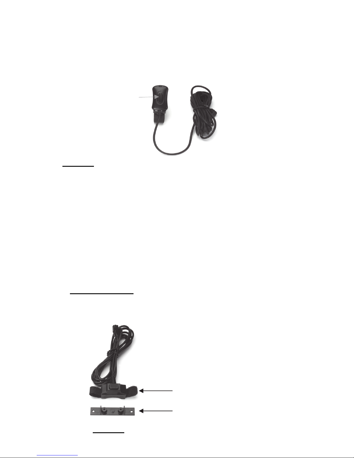
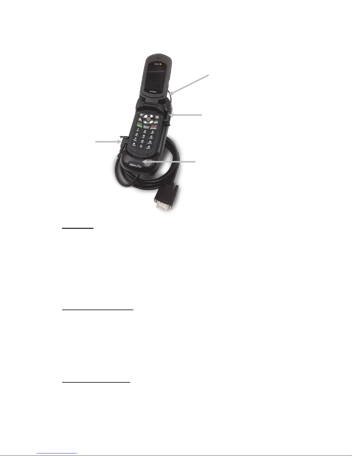
Hands‐freeInstallation
Beforebeginningtheinstallationprocess,determinethebestlocationsfor
themountingoftheMountingBracket,Hand‐freeCradle,Push‐To‐Talk
(PTT)button,VisorMicrophone,SpeakerandJunctionBox.
Considerthefollowingguidelinewhenplanningtheinstallation:
DOuseallmountinghardwareprovided.
DOensurethatcablesarenotplacedunderstress.
DOfollowproper+and‐connections.
DOcrimpconnectorssecurely.
DONOTattachcomponentstoanypartofthevehiclethatisnot
rigidorissubjecttoexcessivevibration.
DONOTinstallcomponentsinareaswhererainorsnowcaneasily
getintothem,suchasnexttoavehiclewindow,whichmaybeleft
open.
DONOTdresscablesoversharpedgesthatcouldcausewearor
tearingofcableinsulation.
DONOTinstallcomponentsinlocationswheretheymight
interferewiththevehicleoperatororoperatingcontrols.
DONOTinstalltheHands‐freeCradlewhereitwillbedifficultfor
theoperatortoreach.
!WARNING
VEHICLESEQUIPPEDWITHAIRBAGS
Anairbaginflateswithgreatforce.DONOTplaceobjects,including
communicationsequipment,intheareaovertheairbagorintheairbag
deploymentarea.Ifthecommunicationequipmentisimproperlyinstalled
andtheairbaginflates,thiscouldcauseseriousinjury.
Itisrecommendedthattheinstallationofthevehiclecommunication
equipmentbeperformedbyaprofessionalinstaller/techniciantrainedin
therequirementsforsuchinstallations.Anairbag'ssize,shapeand
deploymentareacanvarybyvehiclemake,model,andfrontcompartment
configuration(forexample,benchseatvs.bucketseats).Contactthe

4
vehiclemanufacturer'scorporateheadquarters,ifnecessary,forspecificair
baginformationforthevehiclemake,model,andfrontcompartment
configurationinvolvedinyourcommunicationequipmentinstallation.
A.SpeakerInstallation
1.MounttheSpeakerbeneaththedashboard,onthepassenger'ssideof
thevehicle,outofthewayofthepassenger.DonotmounttheSpeaker
onthedashboardortherearwindowshelf.
2.TheSpeakershouldbelocatedmorethanfourfeetfromthejunction
box.
3.TheSpeakerincludesamountingbracket,permittingittobemounted
inavarietyofways.Loosenthethumbscrewsonthesideofthespeaker
andusingthemountingbracketasatemplate,drillthenecessary
mountingholesandsecurethebracketwiththeself‐tappingscrews
provided.
Diagram1
4.PositiontheSpeakeronthemountingbracketandsecureitby
tighteningthethumbscrews.Themountingbracketisusedto
permanentlymounttheSpeakerinplacewhilepermittingittobetilted
toadesiredangle.
5.Feedthecableoutofsighttothelocationwhereyouintendtomount
thejunctionbox.
6.Thespeakershouldbelocatedatleast3ft(1m)fromthevisor
microphone.Avoidplacingthespeakerwhereitfacesthevisor
microphone.
B.MicrophoneInstallation
1.TheMicrophonesuppliedhasnoisecancellationfeaturesandassuch
theselectionofthecorrectpositionforthemicrophoneisvitalforthe
successfulperformanceoftheCarKit.
\
Mountin
g
Bracket
ThumbScrews

5
2.TheMicrophoneshouldbemountedeitheronthesunvisordirectly
aboveandfacingthedriver,orontheheadlinerjustaboveandfacingthe
driver.
Diagram2
3.Thevisormicrophonehasanoisecancelingfeatureandmustbe
mountedfacingthedriverasshowninthepictureabove.
4.Toavoidvisualorphysicalobstruction,routethemicrophonecable
downinsidethedoormolding.Allowsufficientslackontheconnector
endofthecabletoreachtheJunctionBox.
5.Feedthecabletothelocationwhereyouintendtomountthejunction
box.
Note!Themicrophoneshouldnotbemountednearawindoworina
spotwhereroadandambientbackgroundnoisewouldbesubstantially
high(above85dBSPL).
C.MountingofthePTT
1.ToattachthePTTtothegearlever,strapthePTTaroundthegearlever
usingtheVelcrostripattached,withthecordfacingdown.
Diagram3
Facin
g
thedriver
V
elcro Strip
Flat Plastic

6
2.ToattachthePTTtoaflatsurface,removethe2screwsfromthe
bottomofthePTT,whichholdstheVelcrostripinplace.Removethe
stripsandreplacethesmallplasticpartthatheldthestripsinplacewith
thelargerflatplasticpartsuppliedwiththePTT.Screwthenewplastic
partinplace.
3.Feedthecableoutofsighttothelocationwhereyouintendtomount
thejunctionbox.
Caution:Makesurethereissufficientslackinthecabletoallowthefree
movementofthegearleverwithoutstretchingthePTTcable.
D.InstallingthePowerCable
Caution!TheCarkitshouldbeusedwithanegativegroundelectrical
systemonly.Reversepolarity(positiveground)willtriggerprotection
circuitswhichcausethecablefusetoopen.Checkthegroundpolarity
beforeyoubegintheinstallationtopreventwastedtimeandeffort.12V
DCor24VDCautomotivesystemsaredirectlysupported.Determinethe
bestcableroutetothevehicleignitionforthePowerCablefromthe
locationwhereyouintendtomounttheJunctionBox.
Diagram4
1.Routetheblackleadofthemainpowercabletoaconvenientchassis
groundandtheredleadtothepositivesupplyvoltageconnectionpoint.
Ifitisnecessarytopenetratethefirewall,trytouseanexistingopening.
2.Ifthereisnoexistingopening,drillanewholeapproximately9/16”or
3.5cmindiameter.Makesurethatthereisclearanceontheoppositeside.
Insertagrommetintotheholetopreventdamagetothepowercable.
Whenmakingconnectionsontheenginesideofthefirewall,additional
in‐linefuseholder(included)shouldbeusedattheconnectionpoints.
GREEN MUST GO TO IGNITION OR CONNECTED WITH RED
Diagram5

7
3.Cuttheblackleadtothedesiredlength.
4.Iftheconnectionisbeingmadeunderthedashorinthevehiclecabin,
connecttheblackleaddirectlytothechassisofthevehicle.
5.Iftheconnectionisbeingmadeintheenginecompartment,connect
thein‐linefuseholderbetweentheblackleadofthepowercableandthe
desiredchassisconnectionpoint.
Note!Donotconnecttheblackleadtothenegative(‐)batteryterminal.
TheCarKitcouldbedamagediftherewereamalfunctioninthevehicle’s
electricalsystem.
6.Cuttheredleadtothedesiredlength.Thisleadwillbeconnectedsuch
thatithaspositivesupplyvoltageatalltimes,evenwhenthevehicleis
turnedoff.
7.Iftheconnectionisbeingmadeunderthedashorinthevehiclecabin,
connecttheredleadtoapositivesupplyvoltagepoint.
8.Iftheconnectionisbeingmadeintheenginecompartmentordirectly
tothebattery,connectthein‐linefuseholderbetweentheredleadof
thepowercableandthedesiredpositivevoltageconnectionpoint.
9.Routeandconnectthegreenleadtoaconvenientignitionswitch
supplypointinthevehicle.Ifthegreenleadisnotbeingconnectedtothe
ignition,itMUSTbeconnectedtogetherwiththeredlead.
Note!Anignitionswitchaccessoryterminalcanbeverifiedbymeasuring
theterminalwhileoperatingthevehicle’skeyswitch.Withtheignition
keyinthe“accessoryON”position,theterminalvoltageshouldmeasure
thevehicle’sbatteryvoltage.Withtheswitchinthe“OFF”position,it
shouldmeasurenearzero
StereoMute
Ifthevehicle’sstereosystemsupportsanexternalmutingfeature,route
andconnecttheorangewiretothecarstereosystem.Otherwise,the
orangewiremaybeleftunconnectedandcutoffortiedoutoftheway.
Note!TheCarKitsupportsan“EntertainmentMute”functionwhen
connectedtoacarstereosystemthatprovidesforexternalmuting.This
functioniscompatiblewithsystemsthatmutetheaudiooutputwhen
thecontrollineisconnectedtoground.

8
ConnectingcablestoJunctionBox.
1.Locateapositionforthejunctionboxbeneaththedashboardonthe
passenger'ssideofthevehicleoronthecentersidepostbetweenthe
frontseats.
Itmustbeprotectedfromdirtandmoistureandmustbeafforded
adequatespaceforcooling.Theremustbesufficientspacetoallowfor
connectionofallcabling.
2.DONOTmountthejunctionboxatthisstage.Firstconnectthe
Microphone,PTT,Speaker,PowercableandCradleCabletotheir
correspondingconnectionsontheJunctionBoxasindicatedinDiagram
below.
Diagram6
3.Afterconnectingthepowercable'sconnectortotheJunctionBox,
cutinhalftheredwireattachedtothefusehousingsupplied.Cutthe
longredpowerleadtothedesiredlengthandconnect(crimp)ittothe
oneendofthewiretothefusehousing.
4.Connecttheotherendofthewirefromtheredfusehousingtothe
positive(+)sideoftheignition.Thefusehousingcanbesecuredinplace
byusingaplastictieorscrewthroughtheholeinthefuse'splastic
housing
5.Mountthejunctionboxinplaceusingthe2mountingscrewssupplied.
Insertingandremovingthehandsetfromcradle
1.Removetherubberprotectivecoverfromtheconnectorreceptacle
coveringthemicroUSBconnectorontheleftsideofthehandset
(handsetfacingyou)andalignthemicroUSBconnectorattheendonthe
onecablefromthebackofthecradleandinserttheconnectorintothe
handsetwiththecablefacingDOWN.
2.Removetherubberprotectivecoverfromtheconnectorreceptacle
coveringtheaudioconnectorontherightsideofthehandset(handset
facingyou)andalignthepinconnectorattheendoftheothercablefrom
thebackofthecradleandinserttheconnectorintothehandsetwiththe
cablefacingUP.

9
Diagram7
3.Insertthebottomofthehandsetbehindtheridgeonthecradleand
pressthetopofthehandsetbackintotheCradleasshowninDiagram7
aboveuntilitsnapsintoplace.
4.TurntheHandseton.
5.ToremovethehandsetfromtheCradle,pressthereleasebuttonon
thetopofthecradle.TheHandsetwillsnapforwardoutofthecradle.
CarIgnitionconnection
1.WhenthecarignitionisON,theCarKitwillstayonaslongasthe
cablesareinsertedintobothsidesonthehandset.
2.WhentheignitionisturnedOFFtheCarKitwillturnOFFafter60
minutes.
3.UseofthePTTinthevehiclewillturnontheCarKitfor8minutes,
afterwhichitwillturnoffagain.
Makingadispatchcall
1.Dialthedesirednumberonthehandset’skeypad
2.PressandholddownthePTTbutton.
3.Speaktowardsthevisormicrophone.
4.Adjustthespeakervolumeusingthehandset'svolumecontrol
5.Incomingaudiowillbeheardfromtheamplifiedspeaker.
Press buttonon
topofcradleto
releasephone
Insertside
audiocable
InsertMicro
USB
connector
Insertportablebehind
ridgeonthecradle

10
Makingorreceivingahands‐freetelephonecall
1.Toreceiveanincominghands‐freetelephonecall,presstheGreen
phonekey,onthehandset’skeypadorthePTTbuttonforashortperiod.
Aconfirmationtonethatthecallhasbeenansweredwillbeheard
throughthespeaker
NOTE!IfthePTTbuttonispressedformorethan2secondsitwillreject
andendthecall.
2.Tomakeahands‐freetelephonecall,placethehandsetintothecradle
anddialthedesirednumberonthehandset'skeypadandpressthe
phonekey.
3.Adjustthespeakervolumeusingthehandset'svolumecontrol.
4.Incomingaudiowillbeheardthroughthespeaker.
Note!Forbestaudioduringaninterconnectcallsetthevolumelevelat5
barsorless.
CallWaitinginbothHands‐freemodeandwithPrivacyhandset
1.Toansweranincomingcallduringanactivecall,pressthePTTbutton
forashortperiod.Thiswillputthecurrentcallonholdandanswerthe
incomingcall.
2.AshortpressonthePTTwilltogglebetweenthecalls.
3.PressingthePTTformorethan2secondswillterminatethecall.
Chargingthebattery
1.Withthehandsetturnedoff,thecarkitwillchargethebatteryto60%
inapproximately1hour.Thechargetimewillbelongerifthehandsetis
operationalduringchargetime.
2.Foroperatorconvenience,thehandset’sbacklightwillremainonfor
easeofviewingduringlow/no‐lightconditions.
NOTE!Batterieswillchargewithinthetemperaturewindowof‐10Cto
+40C(50Fto104F).Ifthebatteryisoutsidethetemperaturewindow,
nochargecurrentwillbesuppliedtothebattery.
OperatingSpecifications
Inputvoltagerange:11Vdcto32Vdc
Operatingambient:‐30Cto+60C

11
OptionalExtras
AT7107A–HandsetwithCradle
Part#AT7107A–PrivacyHandsetwithCradle
1.TousethePrivacyHandset,plugtheconnectorontheendofthecoil
cordintothecorrespondingRJ45receptacleontheJunctionBox.See
Diagram6above
2.Anactivecallcanbeterminatedandanincomingcallcanberejected
bypressingthePTTbuttononthebackofthePrivacyhandsetformore
than2seconds.
3.ToswitchfromanactivecallwiththePrivacyhandsettohands‐free
operation,placethePrivacyhandsetintoitscradle.Audiowillthenbe
routedtothespeaker.IfthePTTispressedformorethan2seconds,it
willterminatethecall.
4.IfthePrivacyhandsetisnotplacedintoitscradle,afterthecallis
terminated,aremindertonewillbeheardthroughthespeaker,one
minuteafterallactivityisfinisheduntilthePrivacyhandsetisreturnedto
itshandset.

12
AT8428A–PalmMic.
Part#AT8428A–PalmMic
1.TouseaPalmMic.plugtheconnectorontheendofthecoilcordof
thePalmMic.intothecorrespondingRJ45receptacleonJunctionBox.
SeeDiagram6above.
2.Onceconnected,thepressingoftheswitchonthePalmMic.will
deactivatetheVisorMic.andactivatethePalmMic.
1150NW163rdDrive,Miami,FL33169
T: 305-623-3939 F: 305-623-3996
www.advancetec.com
Table of contents
Other Dura-Max Automobile Accessories manuals
Popular Automobile Accessories manuals by other brands

BICS
BICS BASIC instructions

Thule
Thule 9028XT quick start guide

Calitop
Calitop Calispace Ocean 80 Assembly instructions

Whelen Engineering Company
Whelen Engineering Company Tracer Series installation guide

Ranger design
Ranger design 1506-TC Cargo Plus installation guide

Directed
Directed Directechs MIT6 installation guide