DM10 MACHINE MANUAL
4
Safe Machine Operation
Read this machine manual thoroughly before assembling or
operating the machine. Become familiar with its controls and
proper use before operating. Keep this manual in a handy place
for reference and parts replacement referral. This machine is
designed specifically for the purpose of opening and cleaning
drains. Use it for this purpose - do not use it for other purposes.
Use gloves to protect your hands. Wear them to feed and
retrieve cable. Use a material that can not be easily grabbed
by the cable. Most leather gloves and certain rubber gloves
work well. Duracable Manufacturing Company has each type
available through the Duracable Product Catalog. Also, avoid
the use of loose-fitting clothes or jewelry when operating this
machine. Keep guards in place to protect the operator from the
electric motor and electrical wiring. These guards are for safety
protection and must be in place when running the machine.
Each machine is equipped with an air foot switch. Use of the air
foot switch to operate the machine is required for safe operation.
This allows the machine operator to turn the machine on or o
with the foot while keeping both hands on the cable. Select a
work area free from obstruction with room to work. Keep the
machine within three feet of the pipe opening, allowing only
enough room to work. This is required to shorten the length of
exposed cable, thus providing maximum control in high-torque
situations. Take a position that is comfortable to the left or right
side of the machine for feeding or retrieving cable. For high work
openings, the machine can be placed on its back as conditions
require.
When performing a job, use the smallest blade first. Rinse the
pipe after each blade is run through the line in order to clean out
loosened debris. Then follow with the increasing sizes of blades
until the size used is one that actually scrapes the side of the pipe
or sewer. The cutting blades are flexible and can be compressed
to enter most cleanout openings. Centrifugal force created by
the spinning cable forces the blades to expand to their natural
diameter or to the walls of the pipe. It is advisable to maintain
a very keen cutting edge on the blades at all times. Place two
hands on the cable between the outlet of your machine and the
cleanout, and keep them there at all times during operation.
Your hands placed in the proper position will provide a guide for
the cable.
As the blade makes contact with an obstruction in the line, it
stops the blade from turning and builds torque in the cable.
Do not permit the blade to get hung up in an obstruction for
more than three seconds. Torque buildup can be both helpful
and dangerous. It is helpful when pulled from the obstruction
in a timely manner. When the cable is pulled away, the tension is
released and the blade turns at a high speed. When the blade is
free, feed it back into the obstruction to make use of the built-up
power to clean the line. It is dangerous because excess torque
can cause looping over of the cable. Serious injury to fingers and
hands is possible unless precautions are observed.
When retrieving cable from the line, feed the cable into the
machine until the blade is close to the cleanout opening. Shut
o the machine and hand-feed the remaining cable into the
machine. Use of a Power Cable Feed and Return (PCFR) will
reduce stress and strain on both the drain cleaning machine
and the service technician. Duracable Manufacturing Company
recommends a PCFR unit be used on every Model DM10
machine. This unit mounts in front of the head casting assembly
and with movement of a handle will feed or retrieve cable from
a sewer line. Mounting time for the unit is minimal.
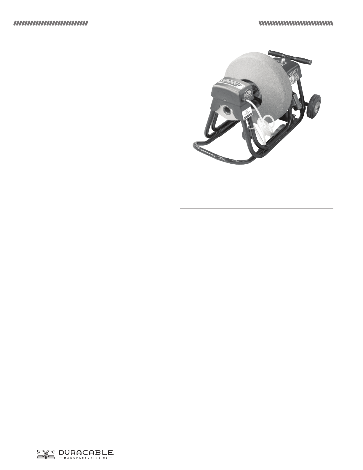
Unpacking Your Machine
The Model DM10 is shipped to you with the following parts:
the base machine, a reel, a revolving arm, a floating ring, and
a floating ring attachment. When it arrives, remove the parts
immediately and inspect for damage. If any of the contents are
damaged, contact your motor freight carrier immediately.
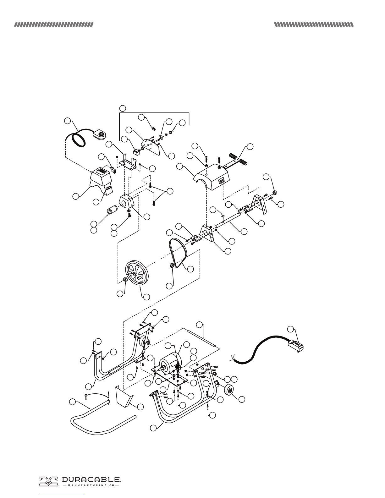
Assembling Your Machine
• Attach the D3L Reel Attachment to the male end on one end
of the cable. Position the cable end with attachment inside the
cable and snap into place. Feed the cable into the reel.
• Set the base machine in a down position on its rails.
• Pick up the reel, loaded with cable, with the cone shape to the
front of the machine (toward the switches) and slide it onto
the reel shaft. Be sure the orange drive lugs slide into the
openings in the back of the reel and engage fully.
• Feed the cable through the revolving arm until it is flush with
the end of the arm.
• Position the revolving arm inside the reel.
• Position the extension shaft on the revolving arm into the
center of the reel bearing.
• Place the revolving arm with cable extended into the rear side
of the head bearing.
• Slide the collar forward using an Allen Wrench to loosen and
tighten the collar.
• Slide the cable through the head bearing.
• To diassemble the DM10, reverse the assembly process.
Moving Your Machine
Break the machine down into lighter-weight components to
move it to and from the job site. To do this, wrap the GFCI cord
and the air foot pedal in a convenient spot on the machine,
remove the revolving arm from its assembled position (leave
the cable inside it and keep it with the reel), and remove the
reel assembly. Various accessories are available from Duracable
Manufacturing Company to assist and protect the operator
during the moving process.
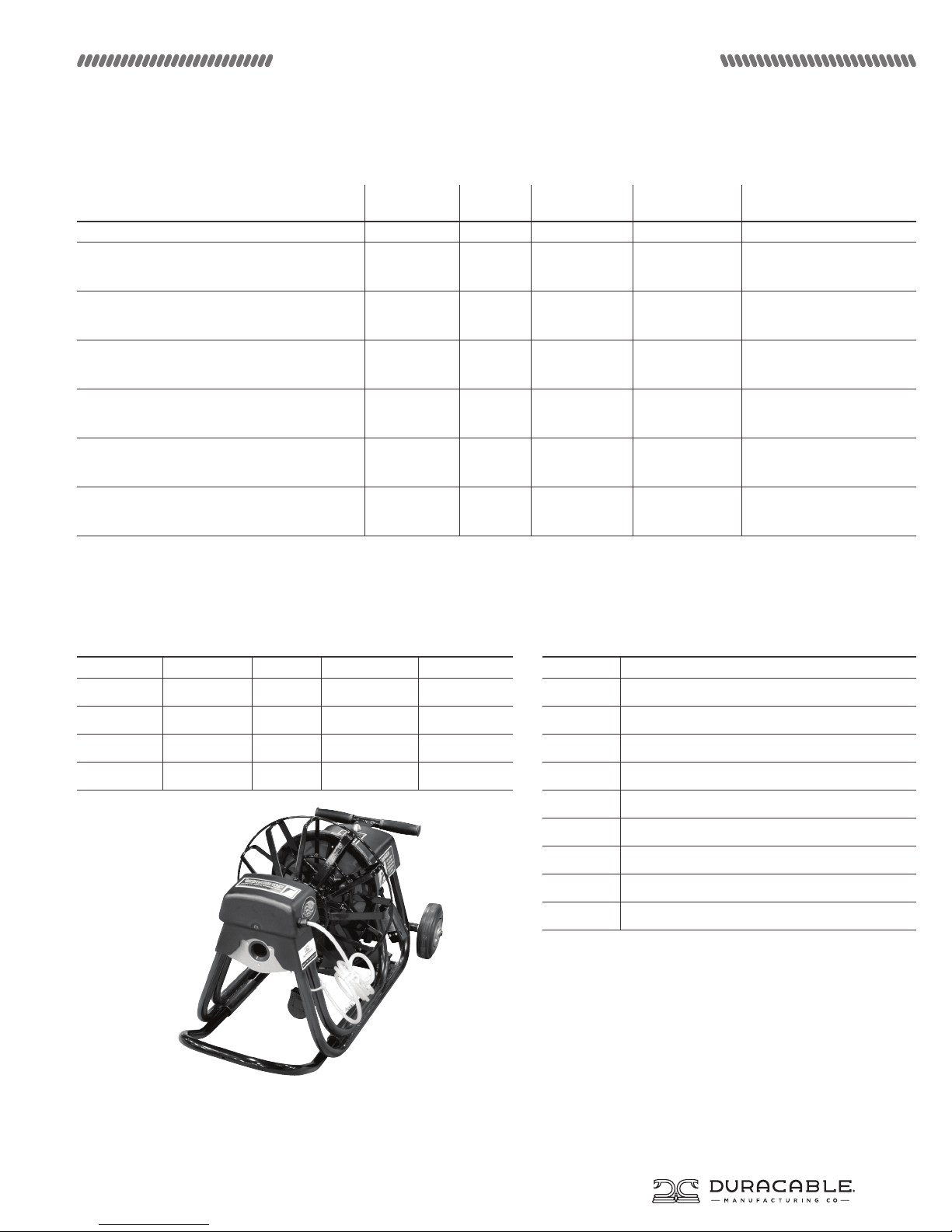
Information and Specifications