Duracell D350-M1 User manual

www.duracellpowercenter.com
Grid Support Utility Interactive Inverter
Range of Input Operating Voltage
Range of Peak Power MPPT Voltage
Start-up Voltage
Max Input Current
Max Input Short Circuit Current
Nominal Output Voltage
Max Continuous Output Current
Nominal Output Frequency
Max Continuous Output Power
Output Power Factor Rating
Peak Conversion Eciency
Type of Enclosure
Operating Ambient Temp
16 ~ 60 V d.c.
33 ~ 48 V d.c.
22 V d.c.
11.5 A d.c.
15.0 A d.c.
240 V a.c.
1.52 A a.c.
60 Hz
349 VA
> 0.99 (Default)
96.7 %
Type 6
-40 to +65
U
L
1
7
4
1
C
S
A
C
2
2
.
2
N
o
.
1
0
7
.
1
-
1
6
Made in China
Model:
D350-M1
C
US
261002
T
h
i
s
d
e
v
i
c
e
c
o
m
p
l
i
e
s
w
i
t
h
p
a
r
t
1
5
o
f
t
h
e
F
C
C
R
u
l
e
s
.
O
p
e
r
a
t
i
o
n
i
s
s
u
b
j
e
c
t
t
o
t
h
e
f
o
l
l
o
w
i
n
g
t
w
o
c
o
n
d
i
t
i
o
n
s
:
(
1
)
T
h
i
s
d
e
v
i
c
e
m
a
y
n
o
t
c
a
u
s
e
h
a
r
m
f
u
l
i
n
t
e
r
f
e
r
e
n
c
e
,
a
n
d
(
2
)
t
h
i
s
d
e
v
i
c
e
m
u
s
t
a
c
c
e
p
t
a
n
y
i
n
t
e
r
f
e
r
e
n
c
e
r
e
c
e
i
v
e
d
,
i
n
c
l
u
d
i
n
g
i
n
t
e
r
f
e
r
e
n
c
e
t
h
a
t
m
a
y
c
a
u
s
e
u
n
d
e
s
i
r
e
d
o
p
e
r
a
t
i
o
n
.
Power Center+
CAUTION:
R
i
s
k
o
f
e
l
e
c
t
r
i
c
s
h
o
c
k
–
D
o
n
o
t
r
e
m
o
v
e
c
o
v
e
r
.
N
o
u
s
e
r
s
e
r
v
i
c
e
a
b
l
e
p
a
r
t
s
i
n
s
i
d
e
.
R
e
f
e
r
s
e
r
v
i
c
i
n
g
t
o
q
u
a
l
i
f
i
e
d
s
e
r
v
i
c
e
p
e
r
s
o
n
n
e
l
.
B
o
t
h
a
c
a
n
d
d
c
v
o
l
t
a
g
e
s
o
u
r
c
e
s
a
r
e
t
e
r
m
i
n
a
t
e
d
i
n
s
i
d
e
t
h
i
s
e
q
u
i
p
m
e
n
t
.
E
a
c
h
c
i
r
c
u
i
t
m
u
s
t
b
e
i
n
d
i
v
i
d
u
a
l
l
y
d
i
s
c
o
n
n
e
c
t
e
d
b
e
f
o
r
e
s
e
r
v
i
c
i
n
g
.
W
h
e
n
t
h
e
p
h
o
t
o
v
o
l
t
a
i
c
a
r
r
a
y
i
s
e
x
p
o
s
e
d
t
o
l
i
g
h
t
,
i
t
s
u
p
p
l
i
e
s
a
d
c
v
o
l
t
a
g
e
t
o
t
h
i
s
e
q
u
i
p
m
e
n
t
.
ATTENTION:
R
i
s
q
u
e
d
e
c
h
o
c
é
l
e
c
t
r
i
q
u
e
–
n
e
p
a
s
e
n
l
e
v
e
r
l
e
c
o
u
v
e
r
c
l
e
.
A
u
c
u
n
e
p
i
è
c
e
i
n
t
e
r
n
e
r
é
p
a
r
a
b
l
e
p
a
r
l
’
u
t
i
l
i
s
a
t
e
u
r
.
T
o
u
t
e
r
é
p
a
r
a
t
i
o
n
d
o
i
t
ê
t
r
e
u
n
i
q
u
e
m
e
n
t
c
o
n
f
i
é
e
à
d
u
p
e
r
s
o
n
n
e
l
q
u
a
l
i
f
i
é
.
A
l
’
i
n
t
é
r
i
e
u
r
d
e
l
’
o
n
d
u
l
e
u
r
o
n
r
e
t
r
o
u
v
e
2
t
e
n
s
i
o
n
s
A
C
e
t
D
C
.
C
h
a
q
u
e
c
i
r
c
u
i
t
d
o
i
t
ê
t
r
e
d
é
c
o
n
n
e
c
t
é
i
n
d
i
v
i
d
u
e
l
l
e
m
e
n
t
a
v
a
n
t
c
h
a
q
u
e
e
n
t
r
e
t
i
e
n
.
L
o
r
s
q
u
e
l
e
p
a
n
n
e
a
u
p
h
o
t
o
v
o
l
t
a
ï
q
u
e
e
s
t
e
x
p
o
s
é
à
l
a
l
u
m
i
è
r
e
,
i
l
f
o
u
r
n
i
t
u
n
e
t
e
n
s
i
o
n
D
C
à
c
e
t
a
p
p
a
r
e
i
l
.
CAUTION:
H
o
t
s
u
r
f
a
c
e
s
–
T
o
r
e
d
u
c
e
t
h
e
r
i
s
k
o
f
b
u
r
n
s
–
D
o
n
o
t
t
o
u
c
h
.
A
T
T
E
N
T
I
O
N
:
L
e
s
s
u
r
f
a
c
e
s
c
h
a
u
d
e
s
–
p
o
u
r
r
é
d
u
i
r
e
l
e
r
i
s
q
u
e
d
e
b
r
û
l
u
r
e
–
N
e
p
a
s
t
o
u
c
h
e
r
.
Duracell is a registered trademark of Duracell U.S.
Operations, Inc., used under license. All rights reserved.
www.duracellpowercenter.com
Grid Support Utility Interactive Inverter
Range of Input Operating Voltage
Range of Peak Power MPPT Voltage
Start-up Voltage
Max Input Current
Max Input Short Circuit Current
Nominal Output Voltage
Max Continuous Output Current
Nominal Output Frequency
Max Continuous Output Power
Output Power Factor Rating
Peak Conversion Eciency
Type of Enclosure
Operating Ambient Temp
16 ~ 60 V d.c.
33 ~ 48 V d.c.
22 V d.c.
(2x) 11.5 A d.c.
(2x) 15.0 A d.c.
240 V a.c.
2.92 A a.c.
60 Hz
696 VA
> 0.99 (Default)
96.7 %
Type 6
-40 to +65
U
L
1
7
4
1
C
S
A
C
2
2
.
2
N
o
.
1
0
7
.
1
-
1
6
Made in China
Model:
D700-M2
C
US
261002
T
h
i
s
d
e
v
i
c
e
c
o
m
p
l
i
e
s
w
i
t
h
p
a
r
t
1
5
o
f
t
h
e
F
C
C
R
u
l
e
s
.
O
p
e
r
a
t
i
o
n
i
s
s
u
b
j
e
c
t
t
o
t
h
e
f
o
l
l
o
w
i
n
g
t
w
o
c
o
n
d
i
t
i
o
n
s
:
(
1
)
T
h
i
s
d
e
v
i
c
e
m
a
y
n
o
t
c
a
u
s
e
h
a
r
m
f
u
l
i
n
t
e
r
f
e
r
e
n
c
e
,
a
n
d
(
2
)
t
h
i
s
d
e
v
i
c
e
m
u
s
t
a
c
c
e
p
t
a
n
y
i
n
t
e
r
f
e
r
e
n
c
e
r
e
c
e
i
v
e
d
,
i
n
c
l
u
d
i
n
g
i
n
t
e
r
f
e
r
e
n
c
e
t
h
a
t
m
a
y
c
a
u
s
e
u
n
d
e
s
i
r
e
d
o
p
e
r
a
t
i
o
n
.
Power Center+
CAUTION:
R
i
s
k
o
f
e
l
e
c
t
r
i
c
s
h
o
c
k
–
D
o
n
o
t
r
e
m
o
v
e
c
o
v
e
r
.
N
o
u
s
e
r
s
e
r
v
i
c
e
a
b
l
e
p
a
r
t
s
i
n
s
i
d
e
.
R
e
f
e
r
s
e
r
v
i
c
i
n
g
t
o
q
u
a
l
i
f
i
e
d
s
e
r
v
i
c
e
p
e
r
s
o
n
n
e
l
.
B
o
t
h
a
c
a
n
d
d
c
v
o
l
t
a
g
e
s
o
u
r
c
e
s
a
r
e
t
e
r
m
i
n
a
t
e
d
i
n
s
i
d
e
t
h
i
s
e
q
u
i
p
m
e
n
t
.
E
a
c
h
c
i
r
c
u
i
t
m
u
s
t
b
e
i
n
d
i
v
i
d
u
a
l
l
y
d
i
s
c
o
n
n
e
c
t
e
d
b
e
f
o
r
e
s
e
r
v
i
c
i
n
g
.
W
h
e
n
t
h
e
p
h
o
t
o
v
o
l
t
a
i
c
a
r
r
a
y
i
s
e
x
p
o
s
e
d
t
o
l
i
g
h
t
,
i
t
s
u
p
p
l
i
e
s
a
d
c
v
o
l
t
a
g
e
t
o
t
h
i
s
e
q
u
i
p
m
e
n
t
.
ATTENTION:
R
i
s
q
u
e
d
e
c
h
o
c
é
l
e
c
t
r
i
q
u
e
–
n
e
p
a
s
e
n
l
e
v
e
r
l
e
c
o
u
v
e
r
c
l
e
.
A
u
c
u
n
e
p
i
è
c
e
i
n
t
e
r
n
e
r
é
p
a
r
a
b
l
e
p
a
r
l
’
u
t
i
l
i
s
a
t
e
u
r
.
T
o
u
t
e
r
é
p
a
r
a
t
i
o
n
d
o
i
t
ê
t
r
e
u
n
i
q
u
e
m
e
n
t
c
o
n
f
i
é
e
à
d
u
p
e
r
s
o
n
n
e
l
q
u
a
l
i
f
i
é
.
A
l
’
i
n
t
é
r
i
e
u
r
d
e
l
’
o
n
d
u
l
e
u
r
o
n
r
e
t
r
o
u
v
e
2
t
e
n
s
i
o
n
s
A
C
e
t
D
C
.
C
h
a
q
u
e
c
i
r
c
u
i
t
d
o
i
t
ê
t
r
e
d
é
c
o
n
n
e
c
t
é
i
n
d
i
v
i
d
u
e
l
l
e
m
e
n
t
a
v
a
n
t
c
h
a
q
u
e
e
n
t
r
e
t
i
e
n
.
L
o
r
s
q
u
e
l
e
p
a
n
n
e
a
u
p
h
o
t
o
v
o
l
t
a
ï
q
u
e
e
s
t
e
x
p
o
s
é
à
l
a
l
u
m
i
è
r
e
,
i
l
f
o
u
r
n
i
t
u
n
e
t
e
n
s
i
o
n
D
C
à
c
e
t
a
p
p
a
r
e
i
l
.
CAUTION:
H
o
t
s
u
r
f
a
c
e
s
–
T
o
r
e
d
u
c
e
t
h
e
r
i
s
k
o
f
b
u
r
n
s
–
D
o
n
o
t
t
o
u
c
h
.
A
T
T
E
N
T
I
O
N
:
L
e
s
s
u
r
f
a
c
e
s
c
h
a
u
d
e
s
–
p
o
u
r
r
é
d
u
i
r
e
l
e
r
i
s
q
u
e
d
e
b
r
û
l
u
r
e
–
N
e
p
a
s
t
o
u
c
h
e
r
.
Duracell is a registered trademark of Duracell U.S.
Operations, Inc., used under license. All rights reserved.
www.duracellpowercenter.com
Grid Support Utility Interactive Inverter
Range of Input Operating Voltage
Range of Peak Power MPPT Voltage
Start-up Voltage
Max Input Current
Max Input Short Circuit Current
Nominal Output Voltage
Max Continuous Output Current
Nominal Output Frequency
Max Continuous Output Power
Output Power Factor Rating
Peak Conversion Eciency
Type of Enclosure
Operating Ambient Temp
16 ~ 60 V d.c.
33 ~ 48 V d.c.
22 V d.c.
(4x) 11.5 A d.c.
(4x) 15.0 A d.c.
240 V a.c.
5.99 A a.c.
60 Hz
1438 VA
> 0.99 (Default)
96.7 %
Type 6
-40 to +65
U
L
1
7
4
1
C
S
A
C
2
2
.
2
N
o
.
1
0
7
.
1
-
1
6
Made in China
Model:
D1500-M4
C
US
261002
T
h
i
s
d
e
v
i
c
e
c
o
m
p
l
i
e
s
w
i
t
h
p
a
r
t
1
5
o
f
t
h
e
F
C
C
R
u
l
e
s
.
O
p
e
r
a
t
i
o
n
i
s
s
u
b
j
e
c
t
t
o
t
h
e
f
o
l
l
o
w
i
n
g
t
w
o
c
o
n
d
i
t
i
o
n
s
:
(
1
)
T
h
i
s
d
e
v
i
c
e
m
a
y
n
o
t
c
a
u
s
e
h
a
r
m
f
u
l
i
n
t
e
r
f
e
r
e
n
c
e
,
a
n
d
(
2
)
t
h
i
s
d
e
v
i
c
e
m
u
s
t
a
c
c
e
p
t
a
n
y
i
n
t
e
r
f
e
r
e
n
c
e
r
e
c
e
i
v
e
d
,
i
n
c
l
u
d
i
n
g
i
n
t
e
r
f
e
r
e
n
c
e
t
h
a
t
m
a
y
c
a
u
s
e
u
n
d
e
s
i
r
e
d
o
p
e
r
a
t
i
o
n
.
Power Center+
CAUTION:
R
i
s
k
o
f
e
l
e
c
t
r
i
c
s
h
o
c
k
–
D
o
n
o
t
r
e
m
o
v
e
c
o
v
e
r
.
N
o
u
s
e
r
s
e
r
v
i
c
e
a
b
l
e
p
a
r
t
s
i
n
s
i
d
e
.
R
e
f
e
r
s
e
r
v
i
c
i
n
g
t
o
q
u
a
l
i
f
i
e
d
s
e
r
v
i
c
e
p
e
r
s
o
n
n
e
l
.
B
o
t
h
a
c
a
n
d
d
c
v
o
l
t
a
g
e
s
o
u
r
c
e
s
a
r
e
t
e
r
m
i
n
a
t
e
d
i
n
s
i
d
e
t
h
i
s
e
q
u
i
p
m
e
n
t
.
E
a
c
h
c
i
r
c
u
i
t
m
u
s
t
b
e
i
n
d
i
v
i
d
u
a
l
l
y
d
i
s
c
o
n
n
e
c
t
e
d
b
e
f
o
r
e
s
e
r
v
i
c
i
n
g
.
W
h
e
n
t
h
e
p
h
o
t
o
v
o
l
t
a
i
c
a
r
r
a
y
i
s
e
x
p
o
s
e
d
t
o
l
i
g
h
t
,
i
t
s
u
p
p
l
i
e
s
a
d
c
v
o
l
t
a
g
e
t
o
t
h
i
s
e
q
u
i
p
m
e
n
t
.
ATTENTION:
R
i
s
q
u
e
d
e
c
h
o
c
é
l
e
c
t
r
i
q
u
e
–
n
e
p
a
s
e
n
l
e
v
e
r
l
e
c
o
u
v
e
r
c
l
e
.
A
u
c
u
n
e
p
i
è
c
e
i
n
t
e
r
n
e
r
é
p
a
r
a
b
l
e
p
a
r
l
’
u
t
i
l
i
s
a
t
e
u
r
.
T
o
u
t
e
r
é
p
a
r
a
t
i
o
n
d
o
i
t
ê
t
r
e
u
n
i
q
u
e
m
e
n
t
c
o
n
f
i
é
e
à
d
u
p
e
r
s
o
n
n
e
l
q
u
a
l
i
f
i
é
.
A
l
’
i
n
t
é
r
i
e
u
r
d
e
l
’
o
n
d
u
l
e
u
r
o
n
r
e
t
r
o
u
v
e
2
t
e
n
s
i
o
n
s
A
C
e
t
D
C
.
C
h
a
q
u
e
c
i
r
c
u
i
t
d
o
i
t
ê
t
r
e
d
é
c
o
n
n
e
c
t
é
i
n
d
i
v
i
d
u
e
l
l
e
m
e
n
t
a
v
a
n
t
c
h
a
q
u
e
e
n
t
r
e
t
i
e
n
.
L
o
r
s
q
u
e
l
e
p
a
n
n
e
a
u
p
h
o
t
o
v
o
l
t
a
ï
q
u
e
e
s
t
e
x
p
o
s
é
à
l
a
l
u
m
i
è
r
e
,
i
l
f
o
u
r
n
i
t
u
n
e
t
e
n
s
i
o
n
D
C
à
c
e
t
a
p
p
a
r
e
i
l
.
CAUTION:
H
o
t
s
u
r
f
a
c
e
s
–
T
o
r
e
d
u
c
e
t
h
e
r
i
s
k
o
f
b
u
r
n
s
–
D
o
n
o
t
t
o
u
c
h
.
A
T
T
E
N
T
I
O
N
:
L
e
s
s
u
r
f
a
c
e
s
c
h
a
u
d
e
s
–
p
o
u
r
r
é
d
u
i
r
e
l
e
r
i
s
q
u
e
d
e
b
r
û
l
u
r
e
–
N
e
p
a
s
t
o
u
c
h
e
r
.
Duracell is a registered trademark of Duracell U.S.
Operations, Inc., used under license. All rights reserved.
Installation Manual

About the Microinverter
This system is composed of a family of microinverters that convert direct current (DC) into alternang current (AC) and
feeds it into the public grid. The system is designed for the incorporaon of one microinverter for one, two, or four
photovoltaic modules. Each microinverter works independently to deliver the maximum power generaon of each
photovoltaic module. This setup enables the user to control the producon of a single photovoltaic module directly,
consequently improving the flexibility and reliability of the system.
About the Manual
This manual contains important instrucons for the D350-M1 / D700-M2 / D1500-M4 microinverters. It must be read in
its enrety before installing or commissioning the equipment. For safety, only qualified technicians, who have received
training or have demonstrated skills can install and maintain this microinverter under the guide of this document.
Other Informaon
Product informaon is subject to change without noce. Please refer to Power Center+ official website at
www.duracellpowercenter.com for the latest version of the installaon manual.
Installation Manual

1Important Notes.............................................................................................................................................. 1
1.1 Product Range......................................................................................................................................... 1
1.2 Target Group ........................................................................................................................................... 1
2 Safety ............................................................................................................................................................. 1
2.1 Important Safety Instructions ................................................................................................................... 1
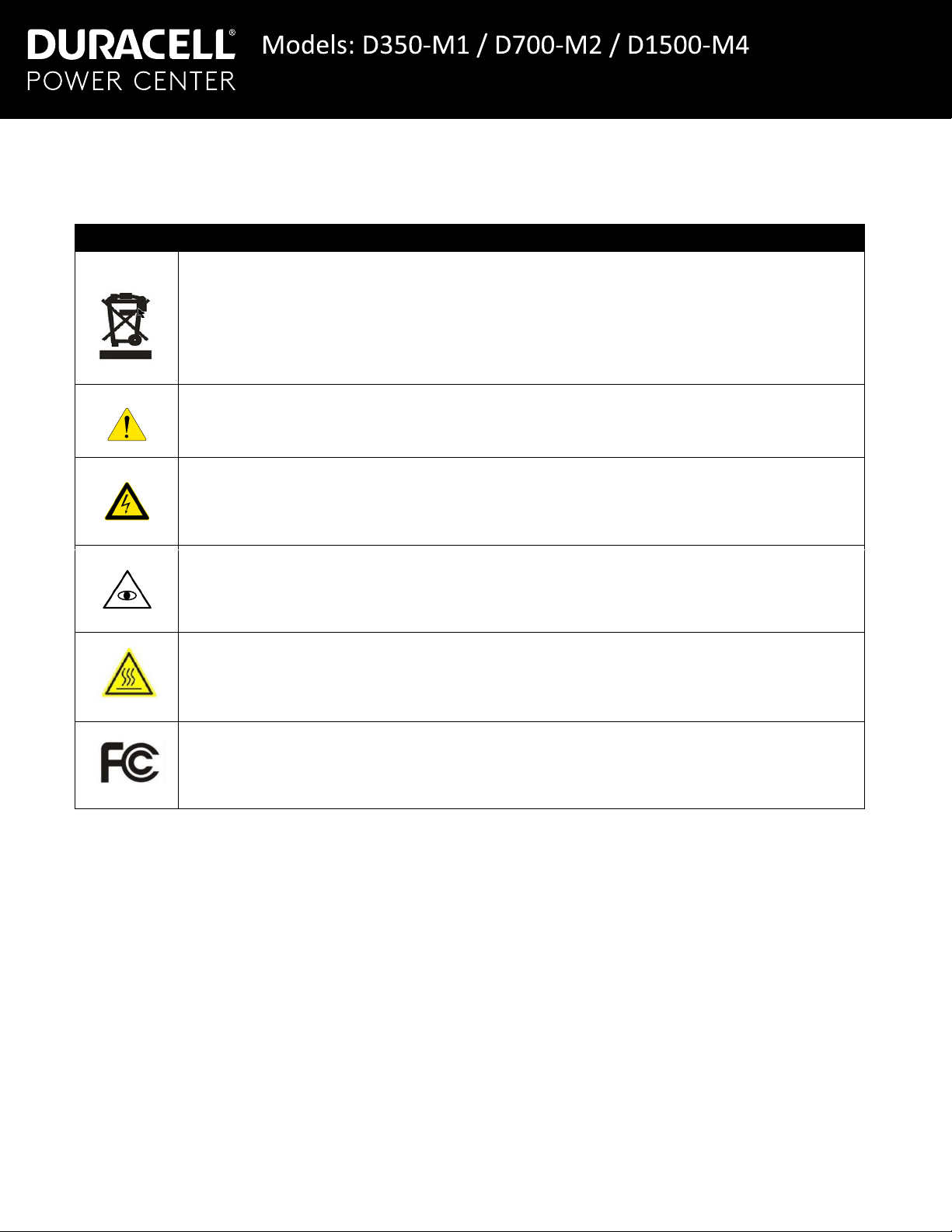
2.2 Explanation of Symbols ........................................................................................................................... 2
2.3 Radio Interference Statement .................................................................................................................. 2
3 Product Introduction ....................................................................................................................................... 3
3.1 Highlights................................................................................................................................................. 3
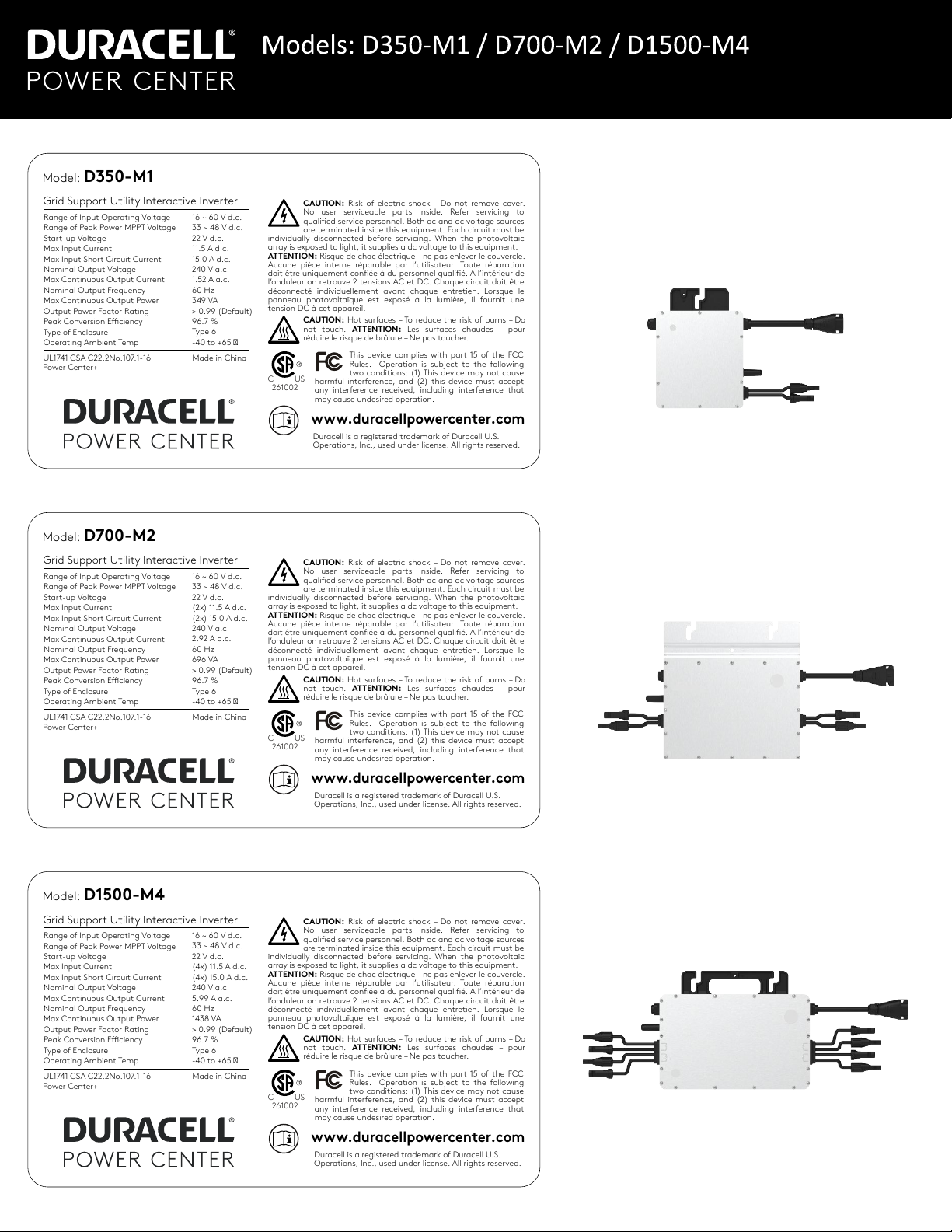
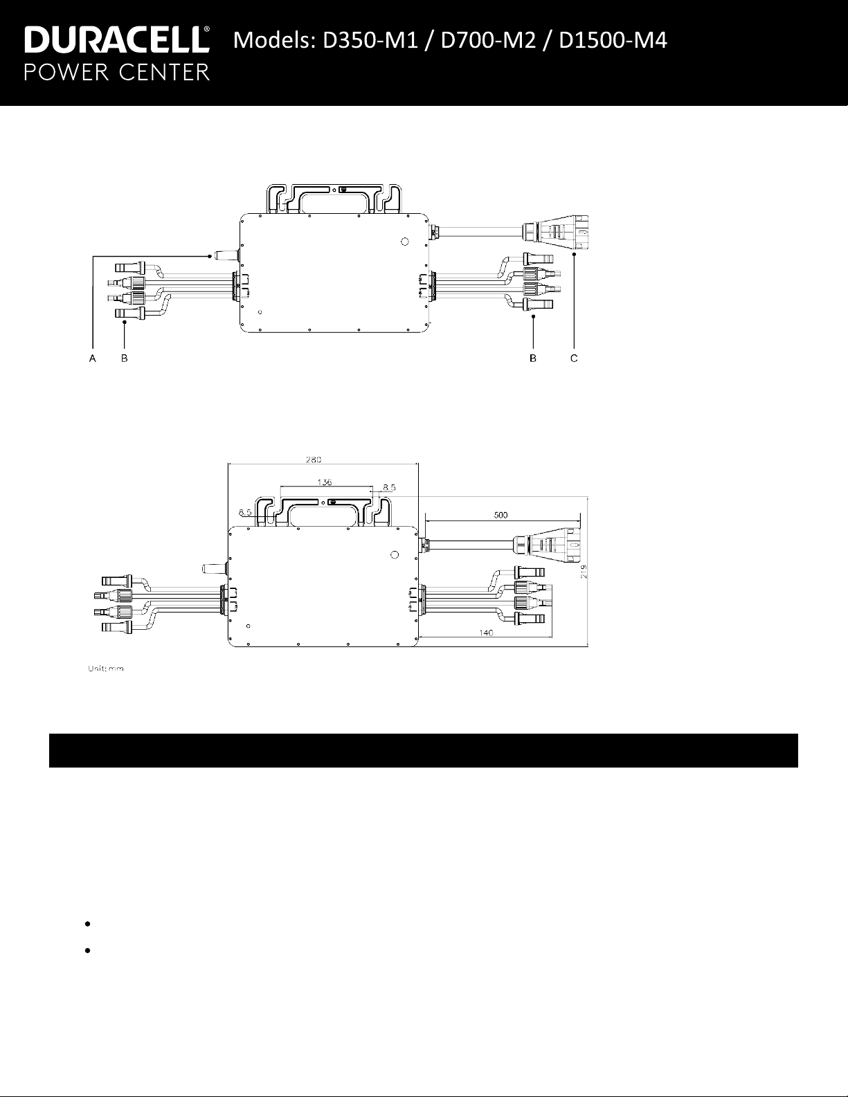
3.1.1 D350-M1: Terminals / Dimensions ...................................................................................................... 3
3.1.2 D700-M2: Terminals / Dimensions ...................................................................................................... 3
3.1.3 D1500-M4: Terminals / Dimensions .................................................................................................... 4
4 Modes of Operation........................................................................................................................................ 4
5Installation Planning ....................................................................................................................................... 5
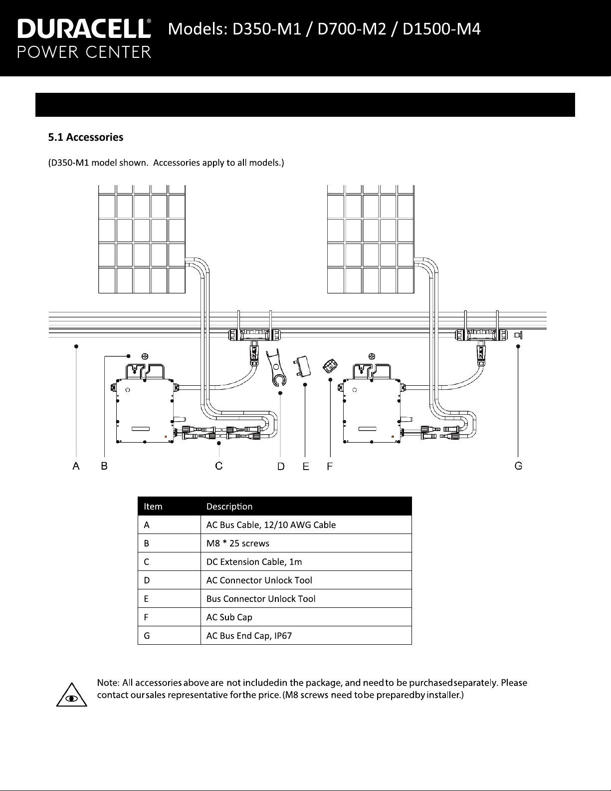
5.1 Accessories ............................................................................................................................................. 5
5.2 Installation Precautions............................................................................................................................ 6
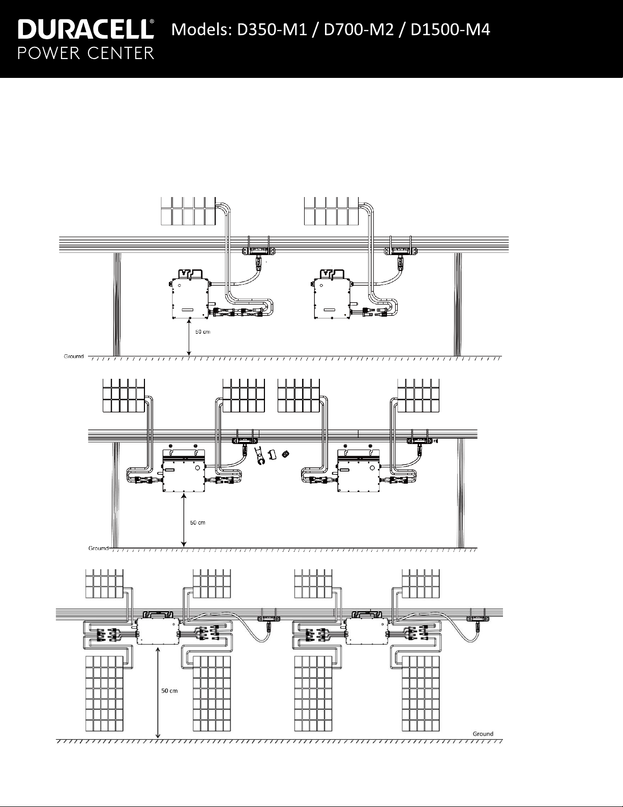
5.3 Space Distance Required ........................................................................................................................ 7
5.4 Preparation .............................................................................................................................................. 8
5.5 Pre-Installation: AC trunk cable end cap installation................................................................................ 8
5.6 Installation: AC trunk cable ...................................................................................................................... 9
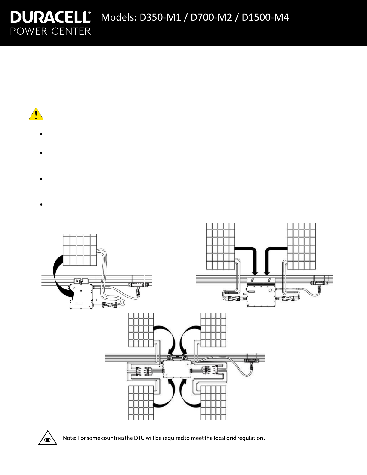
5.7 Installation: mounting the microinverter ................................................................................................. 10
5.8 Installation: Connecting the AC trunk cable to the microinverters.......................................................... 10
5.9 Creating an Installation Map .................................................................................................................. 11
5.10 Installation: PV input port connections................................................................................................. 12
6 Energizing the system .................................................................................................................................. 12
6.1 Setting up the monitoring system........................................................................................................... 12
7 Troubleshooting............................................................................................................................................ 13
7.1 Troubleshooting List: all models............................................................................................................. 13
7.2 Troubleshooting List: D350-M1 / D700-M2 ........................................................................................... 13
7.3 Troubleshooting List: D1500-M4 ........................................................................................................... 14
7.4 Status LED Indicator.............................................................................................................................. 15
7.4.1 Start-up Modes ................................................................................................................................... 15
7.4.2 Run Modes ......................................................................................................................................... 15
7.4.3 Other Status ....................................................................................................................................... 15
7.5 On-site Inspection (For qualified installers only) .................................................................................... 15
7.6 Removing a microinverter...................................................................................................................... 16
7.7 Installing the replacement microinverter ................................................................................................ 16
8 Decommissioning ......................................................................................................................................... 16
8.1 Storage and Transportation ................................................................................................................... 16
8.2 Disposal................................................................................................................................................. 17
9 Routine Maintenance.................................................................................................................................... 17
10Technical Data ............................................................................................................................................ 18
11 Grid Support Details ................................................................................................................................... 19
SA9: Low/High Voltage Ride Through (L/H VRT) and Must Trip Settings .................................................... 19
SA10: Low/High Frequency Ride Through (L/H FRT) and Must Trip Settings ............................................. 19
SA11: Ramp Rate (RR) and Soft Start (SS)................................................................................................. 19
SA12: Specified Power Factor (SPF)........................................................................................................... 20
SA13: Volt/VAr (VV)..................................................................................................................................... 20
SA14: Frequency-Watt (FW) ....................................................................................................................... 20
SA15: Volt-Watt (VW) .................................................................................................................................. 20
Appendix A: Installation Map Template ........................................................................................................... 21
Appendix B: 120/240 Split-phase Electrical Single Line Diagram ................................................................... 22
Appendix C: 120/208 Three-phase Electrical Single Line Diagram ................................................................. 23
Appendix D: AC branch limit calculator ........................................................................................................... 24
Installation Manual
Contents
Installation Manual

1
1.1 Product Range
This manual describes the assembly, installaon, commissioning, and maintenance of the following models of Power Center+
microinverters:
D350-M1 / D700-M2 / D1500-M4
1.2 Target Group
This manual is only for qualified technicians, who have been trained or have demonstrated skills to install and maintain
this microinverter under the guide of this document for safety purposes.
2.1 Important Safety Instrucons
The microinverters are designed and tested according to internaonal safety requirements. However, certain safety
precauons must be taken during installaon and operaon. The installer must read and follow all instrucons, cauons
and warnings in this installaon manual.
All operaons including transport, installaon, start-up and maintenance, must be carried out by qualified, trained personnel.
Before installaon, check the unit to ensure free of any transport or handling damage, which could affect insulaon integrity or safety
clearances. Choose the installaon locaon carefully and adhere to specified cooling requirements. Unauthorized removal of necessary
protecons, improper use, incorrect installaon and operaon may lead to serious safety and shock hazards or equipment damage.
Before connecng a microinverter to the power distribuon grid, contact the local power distribuon grid company to get appropriate
approvals. This connecon must be made only by qualified technical
personnel. It is the responsibility of the installer to provide external
disconnect switches and Over current
Protecon Devices (OCPD).
Only one photo voltaic module can be connected to one input of the inverter. Do not connect baeries
or other sources of power supply.
The inverter can be used only if all the technical characteriscs areobserved and applied.
Do not install the equipment in adverse environment condions such as flammable, explosive,corrosive, extreme high or low
temperature, and humidity. Do not use the equipment when the safety devices do not work or disabled.
Use personal protecve equipment, including gloves and eye protecon during the installaon.
Inform the manufacturer about non-standard installaon condions.
Do not use the equipment if any operang anomalies are found. Avoid temporary repairs.
All repairs should be carried out using only qualified spare parts, which must be installed in accordance with their intended
use and by a licensed contractor or authorized Power Center+ service representave.
Liabilies arising from commercial components are delegated to their respecve manufacturers.
Anyme the inverter has been disconnected from the public network, please be extremely cauous as some components can retain charge
sufficient to create a shock hazard. Prior to touching any part ofthe inverter please ensure surfaces and equipment are under touch safe
temperatures and voltage potenals before proceeding.
Power Center+ accepts no liability for damage from incorrect or improper operaon.
Electrical Installaon & Maintenance shall be conducted by alicensed electrician and shall comply with Local Wiring Rules.
1 Important Notes
2 Safety
Installation Manual
Installation Manual

2.2 Explanaon of Symbols
2.3 Radio Interference Statement
This microinverter has been tested and found to comply with the limits for part 15 of FCC rules, which can provide reasonable
protecon against harmful energy. However, if not installed according to the instrucons, the microinverter may cause
harmful interference to radio equipment. There is no guarantee that the interference will not occur in a parcular installaon.
To confirm that the radio or television recepon is interfered by this equipment, you can turn the equipment offand on. If this
equipment does cause harmful interference to the radio or television equipment, please try to correct the interference by one
or more of the following measures:
1Relocate the receiving antenna.
2Increase the separaon between the microinverter and the receiving antenna.
3Contact your dealer or an experienced radio/TV technician for help.
Symbol
Usage
Treatment
To comply with the European Direcve 2002/96/EC on waste Electrical and Electronic Equipment and its
implementaon as naonal law, electrical equipment that has reached the end of its life must be collected separately
and returned to an approved recycling facility. Any device no longer required must be returned to an authorized dealer
or approved collecon and recycling facility.
Cauon
Indicates direcons which must be fully understood and followed in enrety in order to avoid potenal safety
hazards including equipment damage or personal injury.
Danger of high voltages
Indicates a hazardous situaon that can result in deadly electric shock hazards, other serious physical injury, or fire
hazards.
Indicates that the reader should stop, use cauon and fully understand the operaons explained before proceeding.
Beware of hot surface
The inverter can become hot during operaon. Avoid contact with metal surfaces during operaon.
FCC mark
The inverter complies with the requirements of part 15 of FCC rules.
2
Installation Manual

3.1 Highlights
Adapted to 60 & 72 cells PV panels.
Peak efficiency 96.70%; CEC weighted efficiency 96.50%.
Stac MPPT efficiency 99.80%; Dynamic MPPT efficiency 99.76% in overcast weather.
Power factor (adjustable) 0.8 leading……0.8 lagging.
External antenna for stronger communicaon with the DTU.
High reliability: NEMA6 (IP67) enclosure; 6000V surge protecon.
3.1.1 D350-M1: Terminals / Dimensions
3.1.2 D700-M2: Terminals / Dimensions
A – DC connector B – Antenna C – AC connector
A – AC connector B – DC connector C – Antenna
3 Product Introduction
3
Installation Manual

4
3.1.3 D1500-M4: Terminals / Dimensions
Normal: Under this mode, the microinverter is operang normally and converts DC power into AC power to support the house
loads and feed into the grid.
Zero Export Control: Under this mode, the microinverter’s generaon is limited to the real-me house loads, and there will
be no extra power feed into the grid. External metering required for this operaon. Consult dealer for more details.
Stand by: There are several circumstance that the microinverter will stay in Standby mode:
The current condion is outside of range of the microinverter operang requirement.
No house loads or the Export control value has been set as “0” on the DTU while in zero export control mode.
A – Antenna B – DC connectors C – AC connector
4 Modes of Operation
Installation Manual

5
5 Installation Planning
Installation Manual

6
5.2 Installaon Precauons
Please install the microinverter and all DC connecons under a PV module to avoid direct sunlight, rain exposure, snow
accumulaon, UV etc. Allow a minimum of 2 cm of space around the microinverter enclosure to ensure venlaon and heat
dissipaon.
Warning! Be sure to verify the following before installing the microinverter system:
Verify that the voltage and current specificaons of the PV module match those of the microinverter.
The maximum open circuit voltage rang of the PV module must within the operang voltage range of the
microinverter.
The maximum current rang at MPP is recommended to be equal to or less than the maximum input DC current. The
maximum short circuit current must be equal to or less than the maximum input DC short circuit current.
The output DC power of PV module is NOT recommended to exceed 1.35 mes the output AC power of the
microinverter. Refer to Warranty Terms & Condions for more informaon.
D350-M1
D700-M2
D1500-M4
Installation Manual

7
5.3 PC-PRO Wi-Fi communicaon limitaons
If the microinverters are installed on a concrete roof or steel roof, the communicaon with the PC-PRO DTU may be slightly
affected. Under such installaon condions, it is beer for the microinverters to be installed 50cm above the roof. Otherwise,
addional DTUs (large arrays) may be required to ensure the communicaon quality between the DTUs and the
microinverters. Residenal rooop installaons with metal roofs may require the DTU to be installed closer to the PV array.
D350-M1
D700-M2
D1500-M4
Installation Manual

8
5.4 Preparaon
Installaon of the equipment is carried out based on the system design and the place in which the equipment is installed.
The installaon must be carried out with the equipment disconnected from the grid (powerdisconnect switch open)
and with the photovoltaic modules shaded or isolated.
Refer to the Technical Data to make sure the environmental condions fit the microinverter’s requirement (degree
of protecon, temperature, humidity, altude, etc.)
To avoid power de-rang due to an increase in the microinverter internal temperature, do not expose it to direct
sunlight.
IMPORTANT! To avoid overheang, always make sure the air flow around the inverter is not blocked.
Do not install in places where gasses or flammable substances may be present.
Avoid electromagnec interference that can compromise the correct operaon of electronicequipment.
When choosing the posion of installaon, comply with the following condions:
Install only on structures specifically conceived for photovoltaic modules.
Install the microinverter underneath a photovoltaic module to shade it from direct sunlight.
D350-M1
D700-M2
D1500-M4
Installation Manual

9
From the open end of the trunk cable reel, replace the cable end with an end cap at the bus connector.
1Use the bus connector unlock tool to unlock the port upper cover.
2Loosen the three screws with the
screwdriver. Unghten the cap as
circled below, and remove the extra
cable.
3Screw the cap back to the port, and plug in the AC bus end cap.
4Plug the upper cover back to the bus connector.
5.6 Installaon: AC trunk cable
1Route the trunk cable such that the bus connectors align with the centers of the PV module (single) and/or PV module
cluster (dual / quad).
IMPORTANT! Insert the AC Sub Cap (secon 5.1 - item F) over any unused bus connectors.
2Repeat the steps in secon 5.5 above to separate the trunk cable reel from the first unused bus connector in the PV
array branch.
IMPORTANT! Do not exceed the combined AC output current rang of 24 Amps per branch. Refer to the table in
Appendix D for a branch limit calculator using different microinverter combinaons.
5.5 Pre-Installaon: AC trunk cable end cap installaon
Installation Manual

10
Note: Refer to Appendix B (split-phase 120/240) or Appendix C (three phase 120/208) at the end of this manual
for the following instrucon:
3Terminate the loose end of the trunk cable in an AC juncon box rated for use and installed as per the
local electrical code.
5.7 Installaon: mounng the microinverter
1Mark the approximate center of each panel / panel cluster on the frame.
2Fix the screw(s) on the rail.
3Hang the microinverter on the screw (see picture below), and ghten the screw(s).The silver cover side of the
Microinverter should be facing the panel.
Installer supplied
juncon box – located at
the PV array
Branch
circuit to
distribuon
panel
Installation Manual

11
1Aach the AC bus cable with the mounng rail, and fix the cable with e wraps.
2Push the AC connector of the microinverter to the trunk cable bus connector unl you hear “click”.
3Plug unused AC connetors with the AC sub cap on the vacant
plug to ensure waterproof and dustproof.
Note: If there is a need to remove the inverter AC cable
from the bus port, please use the AC connector unlock tool
and insert the tool into the side of AC port.
5.9 Creating an Installaon Map
1Peel the removable serial number label from each microinverter (see images below for label locaon).
2Affix the serial number label to the respecve locaon on the installaon map. Mark offpanel clusters that share a single
serial number for dual and quad microinverters as shown in the example below. Print one sheet (see - Appendix A) for
each unique facing panel group based on lt and azimuth.
Quad x
Branch
Dual
Panel
5.8 Installaon: Connecng the AC trunk cable to the microinverters
Installation Manual

12
5.10 Installaon: PV input port connecons
1Turn on the AC breaker of the branch circuit.
2Turn on the main AC breaker of the house. Your system will start to generate power aer the regulated grid ming
sequence has completed.
6.1 Setng up the monitoring system
Refer to the DTU User Manual or DTU Quick Install Guide, and Quick Installaon Guide for Online Registraon to install the
DTU and set up the monitoring system. Product informaon is subject to change without noce.
Download reference manuals at www.duracellpowercenter.com
1. Connect the DC cables from the PV module(s)to the PV input port(s) of the microinverter.
D350-M1
D700-M2
D1500-M4
6 Energizing the system
Installation Manual

13
7.1 Troubleshoong List: all models
Alarm
Code
Title Suggeson
121
Over temperature
protecon
Check the venlaon and ambient temperature at the microinverter. Correct as required.
125
Grid config
parameter
error
Check if the grid configuraon parameter is correct and upgrade again.
126 SW code 126 If the alarm occurs accidentally and the microinverter can sll worknormally, no special
treatment is required.
127 Firmware error
Check if the firmware is correct and upgrade again.
Check the communicaon status between the DTU and the monitoring system or between
the DTU and the microinverter.
128 SW code 128 If the alarm occurs accidentally and the microinverter can sll worknormally, no special
treatment is required.
129 SW code 129
130 Offline
Ensure that the microinverter works normally.
Check the communicaon status between the DTU and the monitoring system or between
the DTU and the microinverter. Correct as required.
141 Grid over voltage
Self-clearing when grid returns to normal range.
If the alarm occurs frequently, check whether the grid voltage is within the acceptable range.
If not, contact the local power operator or change the grid overvoltage protecon limit via
the Power Center+ monitoring system with the consent of the local power operator.
142
10 min value
grid over
voltage
143
Grid under voltage
144
Grid over
frequency
Self-clearing when grid returns to normal range.
If the alarm occurs frequently, check whether the grid voltage is within the acceptable range.
If not, contact the local power operator or change the grid overvoltage protecon limit via
the Power Center+ monitoring system with the consent of the local power operator.
145
Grid under
frequency
146
Rapid grid
frequency change
rate
147 Power grid
outage
Please check whether there is a power grid outage.
148 Grid
disconnecon
Please check whether the AC switch or AC wiring is normal.
149 Island detected
Self clearing when grid returns to normal range.
If the alarms occur frequently on all the microinverters in your staon,contact the local
power operator to check whether there is a grid island.
301 thru
308
HW code
301 thru 308
If the alarm occurs accidentally and the microinverter can sll work normally, no special
treatment is required.
If the alarm occurs frequently and cannot be recovered, contact your dealer or Power
Center+ technical support.
7 Troubleshooting
Installation Manual

14
Alarm
Code
Title Suggeson
205
Port 1
over voltage
Ensure that the PV module open-circuit voltage is less than or equal to the maximum
input voltage.
206
(D700-M2 only)
Port 2
over voltage
207
Port 1
under voltage
Ensure that the PV module open-circuit voltage is less than or equal to the maximum
input voltage.
208
(D700-M2 only)
Port 2
under voltage
209
Port 1 no input
Confirm whether this port is connected to the PV module.
If the PV module is connected, please check the DC cable conneconbetween this port
and the PV module.
210
(D700-M2 only)
Port 2 no input
7.3 Troubleshoong List: D1500-M4
Alarm
Code
Title Suggeson
205
Port 1 & 2
over voltage
Ensure that the PV module open-circuit voltage is less than or equal to the maximum
input voltage.
206
Port 3 & 4
over voltage
207
Port 1 & 2
under voltage
Ensure that the PV module open-circuit voltage is less than or equal to the maximum
input voltage.
208
Port 3 & 4
under voltage
209
Port 1 no input
Confirm whether this port is connected to the PV module;
If the PV module is connected, please check the DC cable conneconbetween this port
and the PV module.
210
Port 2 no input
211
Port 3 no input
212
Port 4 no input
213
Port 1 & Port 2 abnormal
wiring
Check PV input connecons.
214
Port 3 & Port 4 abnormal
wiring
Check PV input connecons.
7.2 Troubleshoong List: D350-M1 / D700-M2
Installation Manual

15
7.4 Status LEDIndicator
The LED flashes five mes at start up. All green flashes (1s gap) indicate
normal start up.
7.4.1 Start-up Modes
Flashing green five mes (0.3s gap): Start-up success
Flashing Red five mes (0.3s gap): Start-up failure
7.4.2 Run Modes
Flashing Fast Green (1s gap): Producing power.
Flashing Slow Green (2s gap): Producing power but one input is
abnormal.
Flashing Slow Green (4s gap): Producing power but there is no
communicaon with the DTU.
Flashing Red (1s gap): AC grid invalid (Voltage or frequency out
of range).
Flashing Red (0.5s gap): There is a non-grid related fault.
7.4.3 Other Status
Flashing Red and Green alternately: Firmware is corrupted.
Note: All faults are reported to the DTU. Refer to the local App of the DTU or Power Center+ Monitoring Plaorm for
more informaon.
7.5 On-site Inspecon (For qualified installers only)
To troubleshoot an inoperable microinverter, follow the steps in the order shown.
1. Verify the ulity voltage/frequency are within ranges as shown in the technical data.
2. Check the connecon to the ulity grid. Verify ulitypower is present at the inverter in queson by removing AC, then
DC power. Never disconnect the DC wires while the microinverter is producing power. Re-connect the DC module
connectors and watch for five short LED flashes.
3. Check the AC branch circuit interconnecon between all the microinverters. Verify each inverter is energized by the
ulity grid as described in the previous step.
4. Make sure that any AC breakers are funconing properly and are closed.
5. Check the DC connecons between the microinverter and the PV module.
6. Verify the PV module DC voltage is within the allowable range as shown in the technical data.
7. If the problem persists, please call Power Center+ customer support.
Warning! Do not try to repair the microinverter. If the troubleshoong fails, please return it to the factory for
replacement.
Installation Manual

16
7.6 Removing a microinverter
1. De-energize the AC branch circuit breaker.
2. Remove the PV panel that is covering the microinverter from the racking, and cover the panel(s) that connect to the PV
input(s).
3. Use a DC rated clamp meter to measure and make sure there is no current flowing in the DC wires between the panel(s)
and the microinverter.
4. Use the AC disconnect tool to remove the AC connectors.
5. Use the DC disconnect tool to remove the DC connectors.
6. Un-screw the fixing screw(s) on the top of the microinverter and remove the microinverter from the PV racking.
7.7 Installing the replacement microinverter
1. Record the new microinverter’s serial number.
2. Ensure the AC branch circuit breaker is OFF, and follow the microinverter installaonsteps to install the replacement
unit.
3. In the monitoring plaorm (if customer already registered the PC-Pro online) select the [Device List]page and locate the
device that you just replaced. Click the down arrow next to the[More] on the right side of the page, and select [Replace].
Input the new microinverter’s serial number and click [Ok] to complete the staon changes.
Remove the microinverters as per secon 7.6 above.
8.1 Storage and Transportaon
Package and protect individual components using suitable means to make the transport and subsequent handling easier.
Transportaon of the equipment, especially by road, must be carried out by suitable ways for protecng the components (in
parcular, the electronic components) from shock, humidity, vibraon, etc. The microinverter storage temperature is -40 to
85 .
It is the customer’s responsibility to examine the condion of the components transported. Upon receipt of a shipment, it is
necessary to check the contents for any external damage as well as verify receipt of all items. Call the delivering carrier
immediately if damage or shortage is detected. If inspecon reveals damage to the inverter, contact the supplier, or an
authorized distributor for repair and/or return.
8 Decommissioning
Installation Manual

17
8.2 Disposal
If the equipment is not used immediately or is stored for long periods, check that it is correctly packed. The
equipment must be stored in well-venlated indoor areas that do not have characteriscs that might damage the
components of the equipment.
Take a complete inspecon when restarng aer a long me or prolonged stop.
Please dispose the equipment properly aer scrapping, which are potenallyharmful to the environment, in accordance with
the regulaons in force in the country of installaon.
Only authorized personnel are allowed to carry out the maintenance operaons and are responsible to report any
anomalies.
Always use the personal protecve equipment provided by the employer when carrying out the maintenance operaon.
During normal operaon, check that the environmental and logisc condions are correct. Make sure that the condions
have not changed over me and that the equipment is not exposed to adverse weather condions and has not been
covered with foreign bodies.
IMPORTANT! DO NOT use the equipment if any problems are found, and restore the normal condions aer the fault
has been removed.
Conduct an annual inspecon on various components, and clean the equipment with a vacuum cleaner or special
brushes.
WARNING! Do not aempt to dismantle the microinverter or make any internal repairs! In order to preserving the
integrity of safety and insulaon, the microinverters are not designed to allow internal repairs!
NOTE: The AC output wiring harness (AC drop cable on the microinverter) cannot be replaced. If the cord is damaged
the equipment should be scrapped.
WARNING! Maintenance operaons must be carried out with the equipment disconnected from the grid (power
switch open) and the photovoltaic modules covered or isolated, unless otherwise indicated.
NOTE: For cleaning, do not use rags made of filamentary material or corrosive products that may corrode parts of
the equipment or generate electrostac charges.
NOTE: Avoid temporary repairs. All repairs should be carried out using only genuine spare parts.
CAUTION! Each branch should provide a circuit breaker.
9 Routine Maintenance
Installation Manual
This manual suits for next models
2
Table of contents
Other Duracell Inverter manuals

Duracell
Duracell Inverter 3000 User manual

Duracell
Duracell DR1000INV User manual

Duracell
Duracell Inverter 1500 User manual

Duracell
Duracell Pocket Inverter 100 User manual

Duracell
Duracell DG2.0i User manual

Duracell
Duracell inverter 1000 User manual

Duracell
Duracell DRINV3000 User manual

Duracell
Duracell D350-Ml User manual

Duracell
Duracell Digital Inverter 800 User manual

Duracell
Duracell duracell User manual