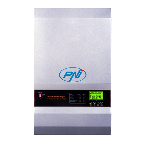
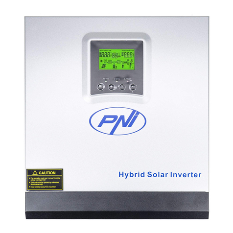
PNI GreenHouse SC1800B User manual

PNI GreenHouse SC1800B
Solar inverter / Invertor solar
EN User manual ......................................................... 3
RO Manual de utilizare ............................................. 39


3User manual
English
About this manual
This manual provides information related to assembly, installation and use, as
well as instructions in case of failure. Please read this manual carefully before
putting the product into operation. Do not throw away this manual, keep it for
future reference.
Safety instructions
WARNING!! This chapter provides important safety information.
1. Before using this inverter, carefully read all instructions and warning marks
on the inverter and battery.
2. To reduce the risk of injury, use only lead acid rechargeable batteries. Other
types of batteries could cause personal injury and product damage.
3. Do not disassemble the product. In case of failure, contact a specialized
service center. Incorrect reassembly of the product could cause electric shock
and even fire.
4. To reduce the risk of electric shock, disconnect all wires before performing
repair and maintenance procedures. Just turning o the inverter does not
reduce the risk of accidents.
5. Only qualified personnel can install the inverter and battery.
6. NEVER charge a frozen battery.
7. For optimal performance, use only the recommended types of cables. It is
very important to use this inverter correctly.
8. Be very careful when walking with metal tools near the battery. There is a
risk of dropping these metal objects on the battery and producing sparks that
could cause a fire.
9. Strictly follow the instructions when you want to disconnect the AC or DC
terminals.
10. The fuses (32VDC for 3KW) provide overcurrent protection for battery
power.
11. GROUNDING INSTRUCTIONS - This inverter must be connected to
a permanently grounded system. Be sure to follow local laws and regulations
when installing this inverter.
12. NEVER short circuit the AC output or DC input. Do not connect to the
power source if the DC input is shorted.
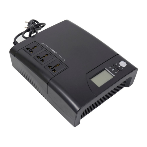
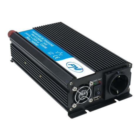
User manual 4
English
Introduction
This is a multifunctional inverter/charger that combines the functions of an
inverter, solar charger and battery charger that oers an uninterrupted power
supply. The LCD screen provides information regarding the configuration and
use of this product according to dierent applications.
Basic characteristics
• Inverter with pure sine wave output.
• Configurable input voltage for powering household appliances and personal
computers.
• Configurable battery charging current.
• Configurable AC or solar charge priority.
• Compatible with the voltage provided by the public power source or with
that provided by a generator
• Auto-restart while AC is recovering.
• Protection against overload, overtemperature, short circuit.
• Intelligent battery charging system to optimize its performance.
Basic system features
The image below shows the standard way of installing and using this inverter.
The system includes:
• A generator (optional, not included) or public power source
• PV modules (not included)
Depending on your requirements and needs, you can create systems with a
dierent architecture than the one presented below.
The inverter can power all kinds of electrical devices in your home, such as
refrigerators, fans, air conditioners, etc..

5User manual
English
Img. 1 Hybrid power system
Battery Appliances
Generator
Utility
PV
Product presentation

User manual 6
English
1. LCD screen 6. On/o button 11. circuit breaker
2. Status indicator 7. AC input 12. RS-485
communication port
3. Charge/discharge
indicator 8. AC output 13. USB port
4. Error indicator 9. PV input 14. Dry-contact
5. Function buttons 10. Battery input 15. USB WiFi
Installation
Before connecting all the wires, remove the top cover by 100sening the screws
as shown in the image below:
Before choosing the installation location, consider the recommendations
below:
• Do not mount the inverter on constructions made of flammable materials.
Mount the inverter only on concrete walls or other non-flammable
materials.
• Mount the inverter on a solid surface.
• For good ventilation of the inverter, keep a distance of at least 20 cm from
one side to the other and at least 30 cm above and below the inverter from
other objects.
• The temperature of the working environment must be between -26°C ~
+80°C.
• Mount the inverter in a vertical position.

7User manual
English
• Install the inverter by fixing two screws in the upper part:

User manual 8
English
Connecting the battery
WARNING!! to install the inverter safely, it is necessary to install a DC
overcurrent protection device and a disconnection device separately between
the battery and the inverter. In some applications it may not be necessary to
install a disconnection device. In any case, the overcurrent protection device
is mandatory. Refer to the table below with recommended amperage and
battery capacity values.
WARNING! All connections must be made by qualified personnel only.
WARNING! It is very important for the safety of the system and the eciency
of use to use only the recommended type and sizes of cable to connect the
battery.
WARNING! The battery bank must be sized directly proportional to the
maximum power of the consumers. Ex: For a maximum consumption of
1500W (sum of consumers) you need a 300 Ah / 24V battery bank.
Recommended cable for battery connection:
Typical amperage Battery capacity Cable size
125A 100AH 1*4AWG
200AH 2*6AWG
Follow the steps below to connect the battery:
1. The 3KW inverter supports 24VDC system. Connect the battery as in the
image below. We recommend that you connect a battery with a capacity of at
least 100Ah.

9User manual
English
2. Fix the battery connection cables to the inverter terminals. To tighten the
rings, use a tubular wrench of 2-3Nm. Pay attention to the polarity.
WARNING!! Risk of electric shock
The installation of the battery must be done with great caution, as it is working
with high current intensity.
WARNING! Do not position anything between the flat part of the inverter
terminals and the connection rings, due to the high temperatures in this area.
WARNING! Do not apply antioxidant substances to the terminals before
making the connections.
WARNING! Before completing all connections, make sure the positive pole
is connected to (+) and the negative pole to (-).
AC source input/output connection
WARNING! Before connecting the AC power source, we recommend that
you separately install an AC breaker between the inverter and the AC source.
Thus, the inverter can be easily disconnected when performing maintenance
operations on the AC source. Recommended AC breaker: 10A for 1kW
inverter, 20A for 2KW inverter, 32A for 3KW inverter.

User manual 10
English
WARNING! There are two terminals marked “IN” and “OUT”. Please do not
connect the input and output connectors incorrectly.
WARNING! all connections must be made by qualified personnel only.
WARNING! For system safety and ecient operation, it is very important to
use the recommended type and size of cable.
Recommended cable sizes
Gauge Torque value
12AWG 1.2~ 1.6Nm
Follow the steps below to make the AC input/output connections:
1. Before making the AC input/output connection, make sure you have opened
the DC protection or disconnection device.
2. Remove the 10mm insulation from the 6 conductors and shorten the Phase
(L) and the neutral conductor (N) by 3mm.
3. Insert the AC input wires respecting the polarity indicated on the terminals,
then tighten the screws of the terminals. Make sure you have connected the
PE protective conductor first ( ).
- Ground (yellow-green)
L-LINE (brown or black)
N-Neutral (blue)

11 User manual
English
WARNING!! Make sure the AC source is disconnected before making
connections.
4. Insert the AC output wires respecting the polarity indicated on the terminals,
then tighten the terminal screws well. Make sure you have connected the PE
protective conductor first ( ).
- Ground (yellow-green)
L-LINE (brown or black)
N-Neutral (blue)
5. Make sure that you have made the connections correctly and that the wires
are well fixed.
WARNING!
Make sure you have connected the AC wires respecting the polarity. If the L
(phase) and N (neutral) wires are connected in reverse, it could cause a short
circuit when the inverters work in parallel.
WARNING!
Devices such as air conditioners require at least 2-3 minutes to start, because
they need time to balance the refrigerant gas inside the circuits. If there is a
power failure, the air conditioner may fail. To prevent this, check if your air
conditioner has a delay start function. Otherwise, the inverter will enter an
overload error and will cut o the supply to the consumer to protect your
device.

User manual 12
English
Connecting photovoltaic modules
WARNING! Before connecting the PV modules, first install a DC circuit
breaker between the inverter and the photovoltaic modules.
WARNING! All connections must be made by qualified personnel only.
WARNING! For system safety and ecient operation, it is very important to
use the recommended type and size of cable.
Amperage Gauge Torque
60A 8 AWG 1.4~1.6Nm
Choosing the PV modules
Before choosing the PV modules, first consult the requirements below:
1. The open circuit voltage (Voc) of the PV modules (photovoltaic modules)
must not exceed the maximum open circuit voltage with the photovoltaic panel
of the inverter
2. The open circuit voltage (Voc) of the PV modules (photovoltaic modules)
must be higher than the minimum voltage of the battery.
Solar charging mode MPPT charger
Inverter 3KW
Charging current 60A
The maximum open circuit voltage of the PV modules 145Vdc
PV panel voltage range 30~120Vdc
Minimum battery voltage for PV charging 17Vdc
System DC voltage 24Vdc
Follow the steps below to connect the PV modules:
1. Remove the 10 mm protection from the positive and negative conductors.
2. Check the connection polarity of the PV module cables and the PV input
connectors. Then, connect the positive pole (+) of the connection cable to

13 User manual
English
the positive pole (+) of the PV module. Connect the negative (-) pole of the
connection cable to the negative (-) pole of the PV module.
3. Make sure all the wires are connected correctly and are securely fastened.
Maximum power (Pmaxl) 260W
Maximum power Voltage Vmpp(V) 30.9V
Maximum power Current Impp(A) 8.42A
Open circuit voltage Voc (V) 37.7V
Short circuit current Isc(A) 8.89A
Maximum number of panels in series: 2 PV
Number of modules in parallel: 4
Total number of PV modules: 2 x 4=8
Installation of solar panels

User manual 14
English
After you have connected all the wires, replace the inverter cover and fix it
with screws.
Communication connections
Please use the included communication cable to connect the inverter to the
computer. Download the software by scanning the QR code at the end of the
manual and follow the on-screen instructions to install the monitoring software.
WARNING! It is forbidden to use the network cable as a communication cable
for the direct connection with the computer.
WARNING! The RJ45 interface is only used to connect other support
products, for professional use.
Configuration diagram of RJ45 pins
1RS-485-B
2RS-485-A
3GND
4
5
6
7
8

15 User manual
English
Dry contact signal
On the rear panel of the inverter there is a dry contact output (relay)
(3A/250VAC). It is used to transmit the signal to external devices when the
battery voltage reaches the alarm level.
Status Condition
Dry
contact
NC&C NO&C
O The unit is o and no consumer is
connected. Close Open
On
Consumers are fed from the public
electricity network Close Open
The
consumers
are powered
from the
battery or
from the
solar source
Program
01
Set as
Utility
Battery
voltage < low
DC voltage
warning
Open Close
Battery
voltage >
set the value
in Program 21
or the battery
enters the
Floating stage
Close Open
Program
01
Set as
SBU
or solar
source
priority
Battery
voltage <
Set the value
in Program 20
Open Close
Battery
voltage >
Set the value
in Program 21
or the battery
enters the
Floating stage
Close Open

User manual 16
English
Instructions for use
Turn the inverter on/o
After the inverter has been installed correctly,
press the on/o button to start the inverter.
Mandatory inverter start-up procedure: 1. Connect the batteries to the
inverter (Use the installed isolation switch); 2. Turn on the inverter from
the ON/O button; 3. Connect the photovoltaic panels (using the installed
isolation switch) 4. Connect the network (if available using the installed
automatic switch); 5. Connect the consumers in turn (if available using the
installed automatic switch).
Mandatory procedure when turning o the inverter / in case of maintenance
or breakdown: 5. Disconnect the consumers (using the installed automatic
switch); 2. Turn o the inverter from the ON/O button; 4. Disconnect
the network (if available using the installed automatic circuit breaker); 3.
Disconnect the photovoltaic panels (using the installed isolation switch) 1.
Disconnect the batteries from the inverter (Use the installed isolation switch);
Control panel and screen
The control panel is located on the front panel of the inverter. Includes 3 LED
indicators, 4 touch keys and the screen to indicate the operating mode or
information about the inputs and outputs of the inverter.
1
2
3
1. LCD screen
2. LED indicators
3. Function keys

17 User manual
English
LED indicators
LED Message
AC/INV Green
On
The consumer
is powered from
the Utility in Line
mode.
Blinking
The consumer is
powered from the
battery or PV in
battery mode
CHG Yellow Blinking
The battery
is charging or
discharging.
Fault Red On Inverter error.
Blinking Warning inverter.
Keys
MENU Access Reset mode or Settings mode; back to the previous
selection
UP Up
DOWN Down
ENTER Access the Settings mode and Confirm the selection in the
settings mode; back to previous selection or exit from Reset mode
Description of icons on the screen

User manual 18
English
Icon Description
Input source information and output source information
Indicates AC information
Indicates DC information
It indicates input voltage, input
frequency, PV voltage, battery
voltage or charging current.
Indicates the output voltage, output
frequency, load in VA, load in Watt
and discharge current.
Configuration program and Error Information
Indicates the settings program.
Indicates error and warning codes.
Warning: Flashes (contains the
warning code).
Error: Flashing (contains the
error code).
Battery information
It indicates the battery level 0-24%,
25-49%, 50-74% and 75-100% in
battery mode and the charging status
in line mode.
In AC mode, it will display the battery charge status.

19 User manual
English
Status Battery voltage LCD screen
Constant current
mode/
Constant voltage mode
< 2V/cell 4 bars will light up in
turn.
2 - 2.083V/cell
The bottom bar will be
lit and the other 3 bars
will blink in turn.
2.083 - 2.167V/cell
The first 2 bottom bars
will be lit and the top
bar will blink.
> 2.167V/cell
The first 3 bottom bars
will be lit and the top
bar will flash.
The batteries are fully charged. The 4 bars will be lit.
In battery mode, it will display the battery capacity.
Loading percentage Battery voltage Icon
Load > 50%
< 1.717V/cell
1.717V/cell ~ 1.8V/ cell
1.8 ~ 1.883V/ cell
> 1.883 V/cell
50% > Load > 20%
< 1.817V/cell
1.817V/cell ~ 1.9V/cell
1.9 ~ 1.983V/cell
> 1. 983V/ cell
Load < 20%
< 1.867V/ cell
1.867V/ cell~ 1.95V/ cell
1.95 ~ 2.033V/ cell
> 2.033V/ cell
Load information
Indicates overload.

User manual 20
English
Indicates the load level 0-24%, 25-
49%, 50-74% and 75-100%.
0-24% 25-
49%
50-
74%
75-
100%
Inverter connected to the public
power grid.
Inverter connected to PV panels.
Consumers are fed from the public
electricity network.
The solar charger works.
The DC/AC circuit of the inverter is
working.
Mute operation
The sound is muted.
LCD settings
After pressing the “ENTER” button for 2 seconds, the inverter enters the
setting mode, then press “ENTER” or “MENU” to confirm the selection and
exit. Press “UP” or “DOWN” to select the settings program.
Other manuals for GreenHouse SC1800B
1
Table of contents
Languages:
Other PNI Inverter manuals