3 Overview
The SG-6005xl is a broadcast quality, multi-standard sync pulse generator
(SPG), with black burst, color bar, and audio tone outputs. It has 10
composite video outputs on BNC connectors, each of which can be
configured as either a black burst or a color bar signal.
In particular, the SG-6005xl:
Features audio outputs that are available in AES-75and AES/EBU
digital formats, as well as in unbalanced and balanced analog audio
formats
Has balanced and AES/EBU outputs on XLR connectors, while the
AES-75and unbalanced outputs are on BNC connectors. All of the
outputs are available simultaneously
Offers a choice of nine color bars, letting you set timing parameters, SCH
and phase
Lets you adjust the frequency and amplitude for the audio signals
Can genlock the SPG to an external composite video source via its
looping input with selectable termination
The SG-6005xl is housed in a 19” 1U rack mountable enclosure, and is fed
from a 100-240 VAC universal switching power supply.
The SG-6005xl can be controlled via the front panel buttons, with an LCD
and a user-friendly menu, and via the RS-232 interface
1
.
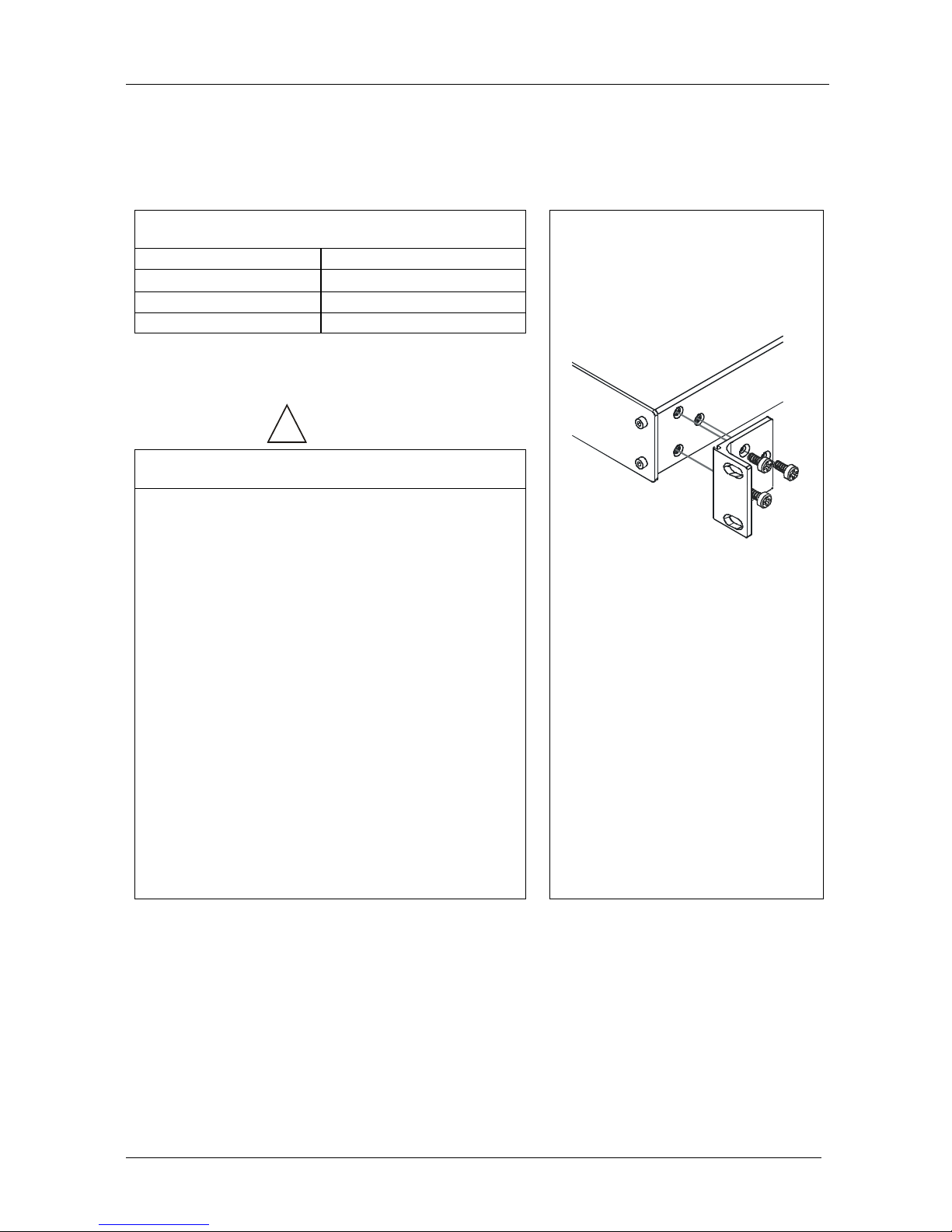
3.1 Recommendations for Best Performance
To achieve the best performance:
Connect only good quality connection cables, thus avoiding interference,
deterioration in signal quality due to poor matching, and elevated noise
levels (often associated with low quality cables)
Avoid interference from neighboring electrical appliances that may
adversely influence signal quality and position your SG-6005xl away
from moisture, excessive sunlight and dust
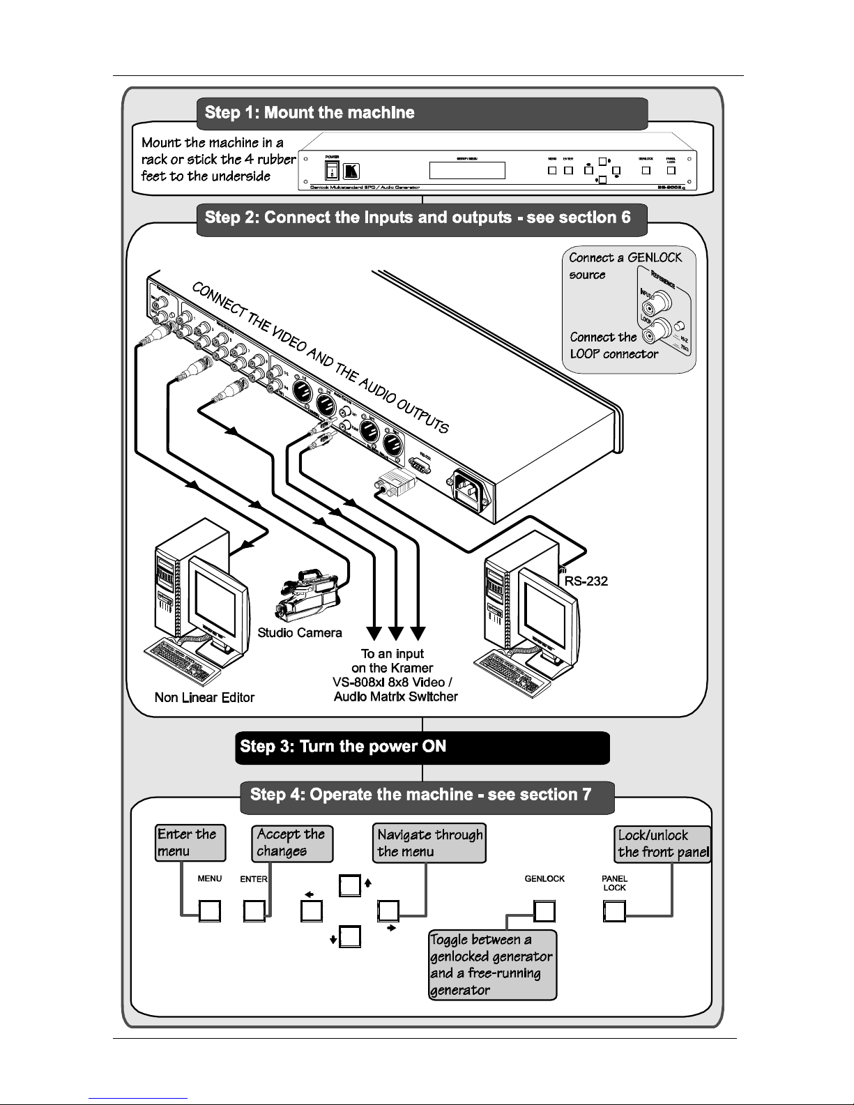
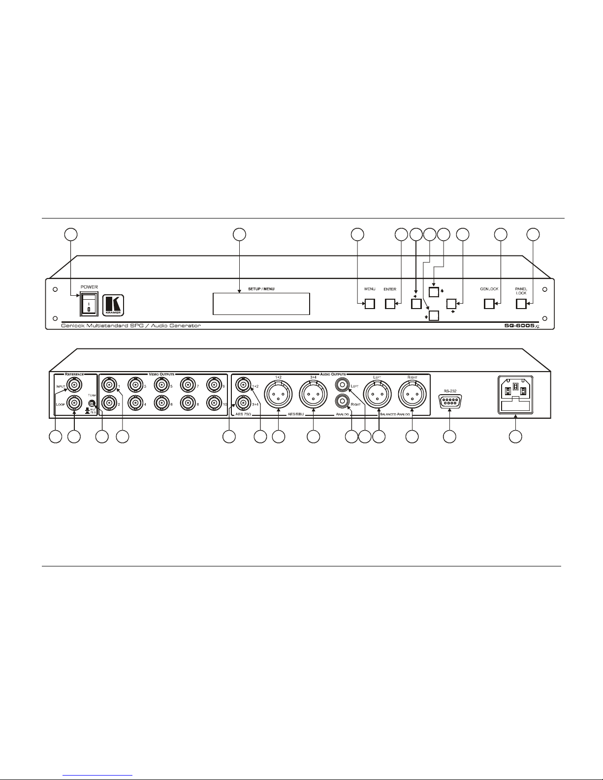
4 Your SG-6005xl Genlock Multistandard SPG / Audio Generator
Figure 1 and Table 1 define the front and rear panels of the SG-6005xl.
1 The Communication Protocol is not available at time of printing. When available, it will be uploaded to our Web site at:
http://www.kramerelectronics.com