Owner's
Manual
Please read this
manual before
installing your
fuse block
Class T Fuse Blocks
CFB1-200
200 Amp
CFB2-400
400 Amp
4
1
11013-CFB1-CFB2-1021
MAN-10006
2 YEAR LIMITED WARRANTY
The CFB1-200 and CFB2-400 fuse blocks manufactured by Samlex America Inc. (the “War-
rantor“) are warranted to be free from defects in workmanship and materials under
normal use and service. The warranty period is 2 years for the United States and Canada,
and is in effect from the date of purchase by the user (the “Purchaser“).
Warranty outside of the United States and Canada is limited to 6 months. For a warranty
claim, the Purchaser should contact the place of purchase to obtain a Return Authoriza-
tion Number.
The defective part or unit should be returned at the Purchaser’s expense to the authorized
location. A written statement describing the nature of the defect, the date of purchase,
the place of purchase, and the Purchaser’s name, address and telephone number should
also be included.
If upon the Warrantor’s examination, the defect proves to be the result of defective mate-
rial or workmanship, the equipment will be repaired or replaced at the Warrantor’s option
without charge, and returned to the Purchaser at the Warrantor’s expense. (Contiguous
US and Canada only)
No refund of the purchase price will be granted to the Purchaser, unless the Warrantor is
unable to remedy the defect after having a reasonable number of opportunities to do so.
Warranty service shall be performed only by the Warrantor. Any attempt to remedy the
defect by anyone other than the Warrantor shall render this warranty void. There shall
be no warranty for defects or damages caused by faulty installation or hook-up, abuse or
misuse of the equipment including exposure to excessive heat, salt or fresh water spray, or
water immersion.
No other express warranty is hereby given and there are no warranties which extend
beyond those described herein. This warranty is expressly in lieu of any other expressed
or implied warranties, including any implied warranty of merchantability, tness for the
ordinary purposes for which such goods are used, or tness for a particular purpose, or
any other obligations on the part of the Warrantor or its employees and representatives.
There shall be no responsibility or liability whatsoever on the part of the Warrantor or
its employees and representatives for injury to any persons, or damage to person or
persons, or damage to property, or loss of income or prot, or any other consequential or
resulting damage which may be claimed to have been incurred through the use or sale of
the equipment, including any possible failure of malfunction of the equipment, or part
thereof. The Warrantor assumes no liability for incidental or consequential damages of
any kind.
Samlex America Inc. (the “Warrantor”)
www.samlexamerica.com
103 - 4268 Lozells Ave.
Burnaby, BC
Canada V5A 0C6
T: 604 525 3836
F: 604 525 5221
TF: 1 800 561 5885
samlex@samlexsolar.com
www.samlexsolar.com
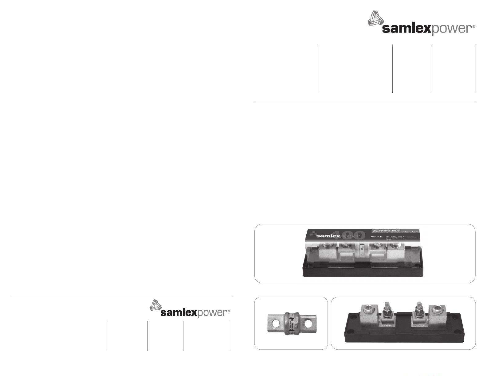
INTRODUCTION
The CFB1-200 and the CFB2-400 are fuse blocks with a 200A and 400A Class T fuse. The
assembly is designed for surface mounting and incorporates a screw down terminal for cable
termination.
These fuse blocks should be installed as close to the battery on the positive side (in a positive
system) to limit injury and damage caused by a short circuit of the positive side of the battery.
CONSTRUCTION
The Class T Fuse Block (Fig. 1) contains the following components:
• Fuse Holder: A berglass insulated base with a removable polycarbonate cover
• Class T Type Fuse: 200A or 400A Fuse (JLLN or equivalent); 20 k Interrupting Capacity (DC)
CFB1-200 comes with a 200A Fuse.
CFB2-400 comes with a 400A Fuse.
• A CFB1 will not support a 400A Fuse and the CFB2 will not support a 200A Fuse
Fig. 1.CFB1 and CFB2 Class “T” Fuse Assembly
Fig 2 Class “T” Fuse and Fuse Block


