DuraComm®Corporation
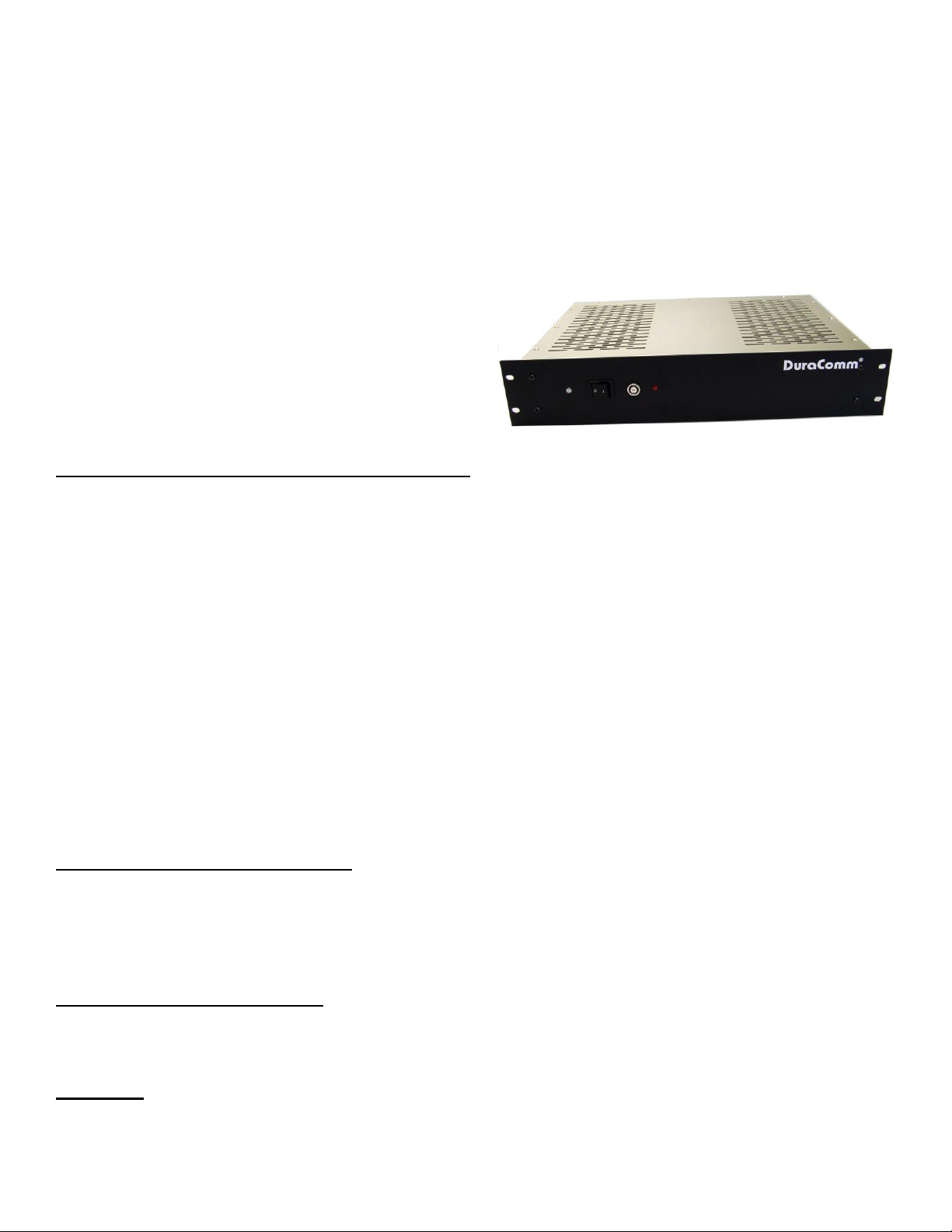
RU2-3012-UPS
RACK MOUNT UNINTERRUPTIBLE POWER SUPPLY
USER GUIDE
(These instructions are intended for use by a technician familiar with electronic products)
●RU2-3012-UPS is a continuous duty uninterruptible power
supply with self contained battery, charger, AC fail circuit,
and low voltage disconnect.
●Recommended for maintaining mission critical equipment.
GENERAL SPECIFICATIONS: POWER SUPPLY
Output Voltage ..................................................................................................................................................................................................13.8 V
Output Voltage Tolerance............................................................................................................................................................................... +/- 1 pct
Output Amperage........................................................................................................................................................................................... 30 cont.
Maximum Power, continuous........................................................................................................................................................................500 watts
Output Voltage Adjustment......................................................................................................................................................................13.8-15 VDC
Maximum ripple and noise................................................................................................................................................................. 100 mV p-p max
Universal AC Input....................................................................................................................................................................................85-264 VAC
Input frequency range....................................................................................................................................................................................47-63 Hz
Maximum AC current..........................................................................................................................................................7A/120 VAC; 3.5/240 VAC
Typical Efficiency..............................................................................................................................................................................................>80 pct
Max inrush current, single cycle............................................................................................................................................................................35 A
Short Circuit protection.....................................................................................................................................................................Foldback Limiting
Overload Protection (operates).......................................................................................................................................................typical 110-120 pct
Line Regulation .................................................................................................................................................................................................50 mV
Load Regulation...................................................................................................................................................................100 mV (20-100 pct load)
Fan Control...........................................................................................................................................................Heat sink temp >140 F (60 C) = ON
Over Temperature...............................................................................................................................................>195 F (90 C) auto output shutdown
Rise Time following ON.....................................................................................................................................................................................50 mS
Hold Time following OFF...................................................................................................................................................................................10 mS
Working Temperature range...............................................................................................................................................+14 ~+140 F (-10 - +60 C)
Storage Temperature .............................................................................................................................................................-4 ~ 185 F (-20 - +85 C)
Withstand Voltage*........................................................................................................................................1.5 KV @ 10 ma (I/P-O/P, I/P-FG)/1 min
(Continued)...................................................................................................................................................500 V @ 10 ma (O/P-FG)/1 min
Dimensions............................................................................................................................................................ 3.5H x 19W x 13D inches, nominal
Weight..................................................................................................................................................................................................20 lbs, nominal
BATTERY BACK UP & CHARGER
Maximum Power, continuous....................................................................................................................................................................... 500 Watts
Auto-revert to battery or power supply..........................................................................................Provided by dual Shottky diode in OR configuration
Maximum output current in battery mode...........................................................................................................30 amps (limited by 30 Amp Breaker)
Maximum charge voltage..............................................................................................................................................................................13.8 VDC
Maximum recharge rate..................................................................................................................................................................1 Amp float charge
Battery protection .................................................................................................................... 30 Amp Breaker Overload/Reverse Polarity protection
L.E.D. indication...................................................................... Red = AC or Power Module Fail, System operating on Battery. Green=DC output OK
LOW VOLTAGE DISCONNECT
Maximum interrupt current / continuous current....................................................................................................................................... 30 Amps DC
Disconnect voltage.......................................................................................................................................................................................11.5 VDC
Reconnect voltage........................................................................................................................................................................................12.5 VDC
Disconnect delay..............................................................................................................................2 minutes @ less than preset disconnect voltage
BATTERY
Power Sonic PS-6100 or equivalent………………………………………………………………………………………………………………………………......x 2
Nominal Voltage…………………………………………………………………………………………………………………………………………………12.0 VDC
Battery Capacity.………………………………………………………………………………………………………………………………………………..12.0 Ah
Operating Temperature……………………………………………………………………..Charge: -4~+122 F(-20~+50C)..Discharge: -40~+140 F(-40~+60C)


 Plus Startup manual")


