•
Turn off all pilot lights or sources of open flame. Ventilation systems
and air moving systems should be turned off. Appliances that
routinely create high heat should be turned off. Computers and other
electrical equipment should be turned off, covered, or removed from
the treatment area.
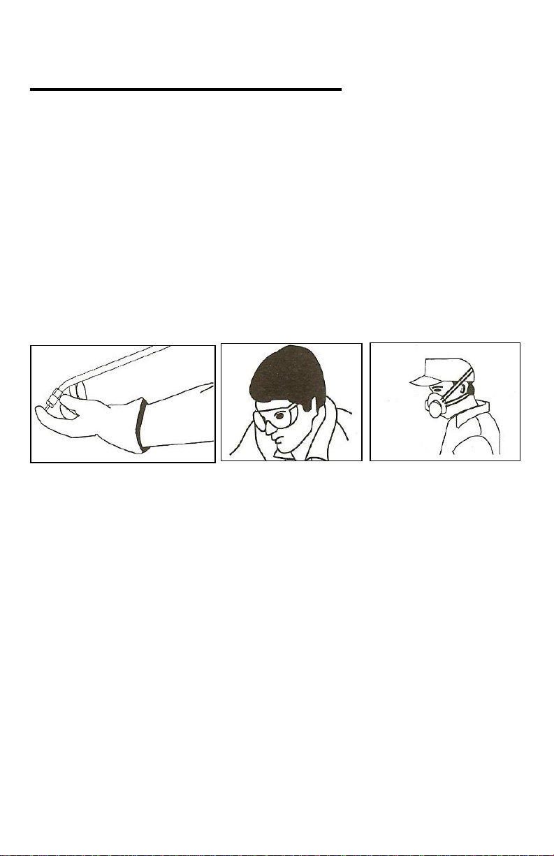
•
All personnel without proper PPE must leave the treatment area.
Cover or remove ornamental plants. Cover and seal all aquariums.
Aquarium filters must be shut off and not turned back on until the
aerosol is no longer present. Pets, including exotic pets (birds,
amphibians, reptiles, arachnids) must be removed. Re-entry for exotic
pets is not recommended for a period of 24 hours.
•
All exposed food must be removed or placed in containers that will
prevent contact with the disinfectant. Food preparation utensils and
surfaces must be covered or cleaned thoroughly before reuse.
•
Close and lock all entry ways. Professionals may want to consider
posting warning signs on doors opening into the treatment site.
•
Open all doors, cabinets, storage areas, and drawers in the treatment
area.
•
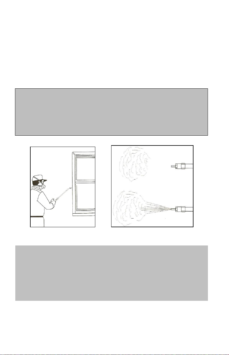
Before reoccupation, thoroughly ventilate treatment area.
•
Do not use gasoline powered equipment in grain mills, flour mills,
grain storage, or grain processing areas. Grain/Flour dust may be highly
explosive. Electric powered units must be certified as explosion proof
for these sites. Check with manufacturers for details on certification.
3.
Filter Disinfectant and Fill Tank.
Remove Fill Cap. Filter disinfectant by pouring slowly into fill neck
and through the in-tank filter to remove any debris that may clog or
damage the DuraSprayer™ equipment.