Durand Tonearms TALEA User manual

DURAND TONEARMS LLC
The
TALEA™
TALEA™ USER GUIDE

TALEA™!!!!©2012 Durand Tonearms LLC.All rights reserved!d
Thank you for choosing the Talea™
We are confident that you will spend many wonderful hours listening to music
with this tonearm.The Talea™was conceived by a musician, for the demands of
musicians’ ears. Just like a musical instrument, each unit is hand assembled and
tuned for maximum performance.
Far from simply being an inert vehicle enabling the transmission of the electrical
signal coming from the cartridge, the tonearm is probably the closest
component to a musical instrument in the audio reproduction chain: like a violin
bow, one of its primary role is to communicate the mechanical vibrations from
the groove. Each of its constituents carries a crucial responsibility in the
transmission of these vibrations, so every element, down to the smallest screw
plays an essential role in the resulting sound. Anyone who has engaged for a
significant period of time with the setup of a sophisticated tonearm knows that
it can take a very long time to understand how it reacts to minute variations
and how to anticipate its reactions and play with them.
USER GUIDE
(2nd Generation)
The
TALEA™

2 TALEA™!!!!©2012 Durand Tonearms LLC.All rights reserved!!!!!!!! 3
Table of Contents
•Introduction!!!!!!! 4
•Mounting!!!!!!! 7
•Assembly!!!!!!!!
!Installing the cartridge in the headshell! ! ! 9
!Installing the armwand on the base! ! ! 11
•Alignment!!!!!!!!
!VTF setting!!!!! !15
!Alignment!!!!! !15
!Offset angle! ! ! ! ! !19
•Final Setup! ! !
!SRA/VTA adjustment!!!!! 21
!Azimuth adjustment! ! ! ! ! 23
•Specifications!!!!!!! 24
•Final considerations! ! ! ! ! ! 24
•What’s in the box?!!!!! !28

TALEA™!!!!!!!!©2012 Durand Tonearms LLC.All rights reserved!!!!!!! !3
While most of the responsibility for the design, choice of materials and final
tuning of the Talea™rests on the shoulders of composer Joël-François
Durand, the process of research and development involved resources and help
from several departments of the University of Washington (Seattle, USA)
including Mechanical Engineering, Materials Science and Engineering, School of
Music and School of Art.
___________
Setting up the Talea™is relatively straightforward, but please follow the
instructions below carefully and in the order presented to ensure proper
setup and prevent damage to any parts of the tonearm.
You should have received the Talea™with the arm base assembled. You will
need to detach the upper plate of the base from the lower one in order to
mount the armwand (see below). Do not attempt to force the armwand on
the pivot without first separating the two plates. This will cause irreversible
damage to the tonearm.
The following instructions are grouped in four sections:
!1. MOUNTING : Mount the tonearm base on your armboard.
!2. ASSEMBLY : Mount and connect the cartridge, and fasten the
upper arm plate on the lower one.
!3. ALIGNMENT: Set the tracking force. Adjust the effective length
and offset angle with the arc protractor included.
!4. FINAL SETUP: Set the stylus rake angle/vertical tracking angle
(SRA/VTA) and the azimuth fine adjustment.
___________
You will see again and again in this manual the mention “Do not overtighten”:
while we might admit that it is probably mentioned one too many times, please
keep in mind that there is no adjustable part in the assembly that requires
brute force. Most screws have fine threads which will be destroyed if too
much force is applied, and no desirable effect will result from overtightening
them.“Finger tight” should be sufficient in most cases.

6 TALEA™!!!!©2012 Durand Tonearms LLC.All rights reserved!!!!!!!! 7
1. MOUNTING
In order to mount the tonearm base on the armboard of your turntable, you
will need to drill holes for the screws (two for mounting on a metal
armboard, four for a wood armboard) that fasten the tonearm base on the
armboard.You will also need to drill a hole on the armboard for the phono
wire clamping. The best position for this clamp is just behind the arm base,
aligned with the bolt at the back of the VTA tower about one inch behind the
plate. If your armboard is in metal, two 10-24 x ¾” bolts are provided, plus
one 10-24 x ½” for the cable clamp--you will need to tap the holes for these
bolts. Four #8 x ¾” wood screws are provided for wood armboards, plus one
for the cable clamp.
Note:The Talea™is designed so that no part of the assembly will extend under
the surface of the turntable plinth, so there is no need to bore a central hole.
In order to find the best position for these bolts/screws, we have provided a
“pivot-to-spindle” jig. Engage the larger hole of the pivot-to-spindle jig into
the turntable spindle.The jig needs to sit flat on the platter, so you might have
to adjust the height of the VTA tower.
The VTA tower should have been secured before shipment. Engage the 7/64”
T-handle allen key (red handle) in the bolt at the back of the tower, and turn
counter-clockwise to loosen the tower (see below, P. 20, for a photo of the
rear of the tower); about ⅛to ¼of a turn is enough.To lower theVTA tower,
turn the VTA knob clockwise; to raise it, turn counterclockwise.
Note: The set screw located at the left side of the VTA tower should not be
loosened. Doing so could render the on-the-flyVTA adjustment inoperable.
Now rotate the tonearm base until you can engage the small hole of the the
jig into the pivot shaft (it extends under the arm plate). While rotating the
base, try to keep the plate that holds the tonearm lift and rest facing forward
(6 o’clock) as best as possible.
Note: these photos were done with the Talea™ first generation; the pivot-to-
spindle jig works in exactly the same way with your second-generation Talea™.

8 TALEA™!!!!©2012 Durand Tonearms LLC.All rights reserved!!!!!!!! 9
Once you have found the best position for the tonearm base, mark on the
armboard the location where the holes will be drilled; it is best to mark that
position so that the holes will be about in the middle of the channels of the
base. If you will be using the two 10-24 bolts, use one for each channel. For
wood armboards, you will use the four wood screws, two in each channel:
these screws should be on each side of the middle, but not all the way at the
end of the channels (so that you have enough room to rotate the base a little
if needed).
When the armboard is ready, engage the two bolts/four screws in the two
channels of the bottom plate, and screw them in the holes of the armboard,
using the 5/32” hex driver (yellow handle) provided with the tonearm if you
are mouting with the 10-24 bolts, or a Philips head screw driver (not
provided with the tonearm) for the wood screws. Note that the 5/32” hex
driver is a ball-end hex driver, which can be used at a maximum 30 degree
angle. Before you tighten the bolts, place the pivot-to-spindle jig in position
again and adjust the arm base so that each hole of the jig is properly engaged
in the pivot shaft and the spindle. If not, rotate the base as necessary. Now
you can tighten the bolts in the armboard.
___________
2. ASSEMBLY
Installing the cartridge in the headshell
!1. Mount the cartridge onto the cartridge plate: first place the small
nut inside the slot on the underside of the cartridge plate.Align the two holes
at the back of the plate with the cartridge mounting holes, making sure that
the slot is toward the front of the cartridge; insert the screws in the holes of
the cartridge plate, then the cartridge; fasten the cartridge to the plate. Refer
to the photo on the facing page to make sure the plate is positioned properly
on the cartridge. It will help to keep the cartridge plate upside down at first
when you place the nut in the slot; holding the plate against the cartridge,
turn the whole assembly and mount the cartridge screws. Do not
overtighten.
With some cartridges that have short or narrow bodies, part of the slot might
extend outside of the body; in this case, there is a chance that the small nut could
fall off the slot as long as it is not yet secured with the headshell bolt.Try to keep
the nut toward the rear of the slot as long as it is not secured by the bolt.

10 TALEA™!!!!©2012 Durand Tonearms LLC.All rights reserved!!!!!!!! 11
!2. Insert the (4-40) headshell bolt into the hole of the headshell, and
thread it into the nut inside the cartridge plate. The cartridge should now be
facing the front of the tonearm. If it is not, check again that the cartridge plate
was mounted in the right direction. Note the small notch at the front of the
cartridge plate: aligning this notch with the center of the bolt in the headshell
will orient the cartridge close to the proper offset angle.
!3. Insert the phono clips of the tonearm into the cartridge pins. Use
extreme caution when manipulating the phono wires and the clips; you can use
the hemostats included with the tonearm (located under the green plastic box
in the lower level of the tonearm box), other types of tweezers or small
needle-nose pliers.
COLOR CODING
Red
Right channel, + (signal)
Green
Right channel, - (ground)
White
Left channel, + (signal)
Blue
Left channel, - (ground)
!4. Insert the rear counterweights on the counterweight tubing at the
rear of the armwand. Selection of the proper counterweights will depend on
the mass of the cartridge and the recommended VTF. In general, it is a good
idea to use counterweights that will lie as close as possible to the pivot point,
but experimentation will be the best guide. Do not tighten the set screws of
the counterweights yet.
Finally, install the small VTF fine adjust weight on the threaded rod at the end
of the counterweight tubing.
Installing the armwand on the base
As mentioned above, you must first separate the upper plate of the base from
the lower plate in order to mount the armwand.
First, loosen the set screw that holds the VTA knob on the VTA tower with
the 1/16” hex driver and place the washer aside. With the Klein Tools Philips-
tip screwdriver provided, unscrew the four screws on top of the VTA tower
and the two screws on the outer wall of the azimuth tower.

12 TALEA™!!!!©2012 Durand Tonearms LLC.All rights reserved!!!!!!!! 13
It is best to leave the screws engaged in the upper arm plate after they are
unscrewed, to avoid losing them. Carefully lift the plate and set it aside (don’t
turn it upside down or on its side, or the little screws will fall off!).
!! Caution !!
The pivot is very sharp. Do not press it hard against the bearing, and avoid contact
with body parts at all times
Lower the armwand onto the pivot. Make sure that the pivot is centered
onto the female part of the bearing (inside the armwand); a few tries might be
necessary to achieve the proper position of the pivot at the bottom of the
bearing. Do not apply any pressure on the bearing.
Make sure that you support the phono cable all the time during this
procedure, until it is securely clamped on the turntable plinth (the cable
is fairly heavy so it will pull strongly on the thin wires). Failure to do this
could result in serious damage to the wires and render the tonearm
useless. Physical damage to the wire is not covered by the warranty.
Check that the thin phono wires are routed properly: they should run inside
the azimuth tower (not under the arm plate), first passing to the side of the
pivot (left or right, as is more convenient for your setup) then exiting to the
back of the arm plate without any hindrance. Attach the clamp of the phono
cable to the turntable plinth with the screw provided in the box. The clamp
should be roughly aligned with the tightening bolt at the back of the VTA
tower.
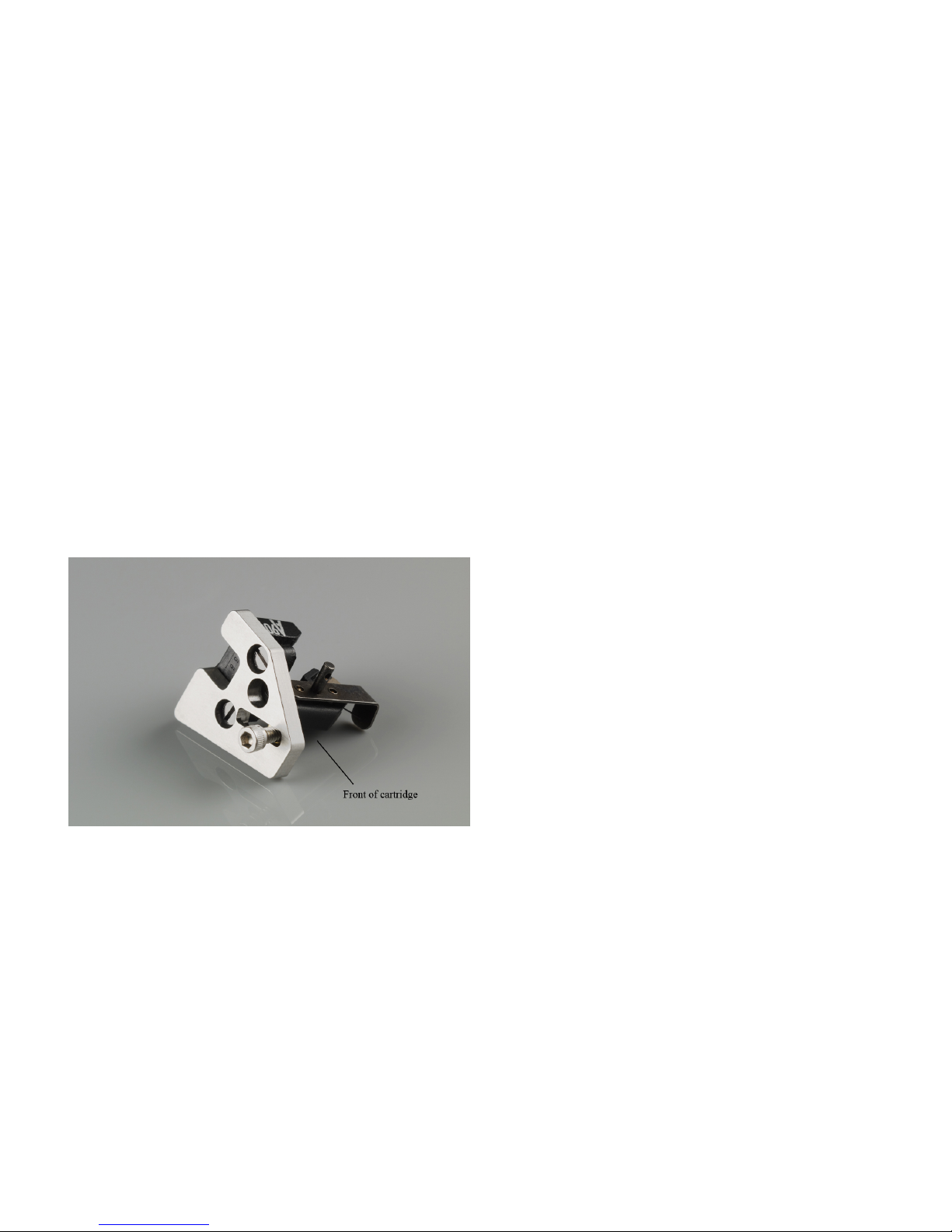
Before placing the upper arm plate back onto the lower arm plate, check the
cartridge position: if the arm is twisted toward the right, as viewed from the
front (cartridge not vertical), you need to insert one of the azimuth weights in
the azimuth bar before proceeding any further. Read carefully the SIDE
COMMENT on the facing page.
Do not change the setting of the azimuth adjustment at this point: since its
range is very limited, you need to first have the cartridge close to vertical so
that you don’t run out of range when you will later adjust the azimuth more
precisely.
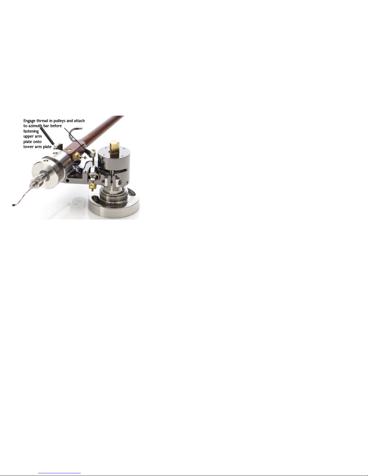
Now is the time to install the anti-skating mechanism: see the Side Comment
on the following facing page (P.14).
SIDE COMMENT
The azimuth bar and azimuth weight
You might need to add one of the two azimuth weights
on the azimuth bar in order to balance the tonearm; this
will depend on the weight and shape of your cartridge,
so feel free to experiment with and without weight.The
goal is to make sure that, once the armwand is mounted
and the upper arm plate is in place, the arm is not overly
twisted in one direction of the other and the cartridge
is near vertical. The easiest way to ensure this is to
choose the appropriate azimuth weight before mounting
the upper arm plate back: place the weight on the
azimuth bar so that the cartridge is as vertical as
possible. (see P.23 below, for more information on the
topic on azimuth adjustment). Tighten the set screw on
these weights with the small 1,3-0.05” hex driver.
Note: when setting up the anti-skating mechanism, it is
important to place the azimuth weight on the azimuth
bar before engaging the anti-skating thread. See P.14.

14 TALEA™!!!!©2012 Durand Tonearms LLC.All rights reserved!!!!!!!! 15
Place the upper arm plate onto the lower one. Screw in the six little screws. It
is recommended to use a “diagonal” pattern when fastening these screws:
start with one screw of the VTA tower, without tightening yet. Then fasten
lightly one screw on the opposite side of the VTA tower; finish the four screw
of the VTA tower, tighten. Then fasten the two screws on the azimuth tower
(do not overtighten these little screws!).
Place the washer and the VTA knob back over the VTA inner column, align the
set screw with the flat part of the column, and tighten.
___________
3. ALIGNMENT
VTF setting
In order to prevent any damage to the stylus, you need to set up the correct
tracking force before proceeding with the alignment. Move the rear
counterweights to get as close as possible to the tracking force recommended
by your cartridge manufacturer. When moving the counterweights, try to not
apply any pressure on the bearing: if you are unsure, slightly lift the armwand
so that the pivot is not in contact with the bearing.
Finer adjustment of the tracking force is done with the smaller weight placed
on the threaded rod at the back of the counterweight. Finally, tighten the set
screws on top of the counterweights.
Alignment
Since you have already placed the arm at the correct pivot-to-spindle distance
(1. MOUNTING), you will now position the cartridge to obtain the proper
effective length and offset angle.
The use of an arc protractor such as the one provided with the tonearm is
highly recommended for this procedure. It will ensure the very precise
measurement of the effective length and its consistency at any position of the
stylus on the record. When using an arc protractor, make sure that the stylus
remains on the arc throughout.
An anti-skating mechanism is provided with the Talea™.
Note that it is much easier to set it up before fastening the upper am plate onto the
lower one--see photo above.
Pass the thread attached to the rear pulley of the anti-skating mechanism inside the
front pulley. Engage the little o-ring at the free end of the thread into the azimuth
bar on the side of the armwand.
Two anti-skating weights are provided with the tonearm. Tighten the set screw on
these weights with the 1,3-0.05” hex driver.

16 TALEA™!!!!©2012 Durand Tonearms LLC.All rights reserved!!!!!!!! 17
Place the arc protractor provided with the tonearm on the platter of your
turntable. Lower the stylus at a position approximately corresponding to the
outer groove and, with the help of a magnifying glass such as the one provided
with the tonearm, rotate the platter until you see that the stylus falls exactly
on the arc; raise the tonearm and bring the stylus close to the center of the
record; lower the arm and note where the stylus falls. If it falls on the line,
you’re done! (that was easy, and very lucky...). If not, there are two options:
•If the stylus falls outside (ahead of) the arc on the protractor, this means
that the distance pivot-stylus is longer than it should be. Loosen the bolt on
the headshell and gently push the cartridge toward the back. Tighten the
bolt and repeat the procedure: first place the stylus on the arc at the
beginning groove, then at several positions until the end of a record, until
the stylus falls on the arc throughout.
•If the stylus falls inside the arc on the protractor, loosen the bolt and gently
pull the cartridge toward the front.
Repeat the procedure until the stylus is perfectly tracing the arc. When it is,
check that the stylus is tracing the arc throughout one more time. Align again
if it is not. When you are done, the spindle-to-pivot distance, effective length
and overhang will all be in place. You may then proceed to adjust the offset
angle.
Note: The protractor provided with the tonearm is based on the Loefgren A
geometry (aka Baerwald). In this geometry, the null points (points where the
cantilever will be exactly tangential to the LP groove, resulting in minimal
tracking error) are at 66 mm and 120.9 mm. Note that the null points are not
indicated on the arc protractor, because the stylus should be tracing the arc
throughout, not just at the null points. This will ensure greater accuracy than
with a traditional two-point protractor.
If you are unable to trace the arc throughout by sliding the cartridge plate in
the headshell, it is probably because the pivot-to-spindle distance was not set
correctly at the beginning. Check it with the pivot-spindle jig, and repeat the
procedure.
Check the alignment in at least two positions of the stylus, one close to
the beginning of an LP, one toward the end.
Make sure you have enough light: one way to do that is to have a
flashlight shining from the side, as seen on the photos above.
Placing the loupe on the side of the tonearm (rather than at the front)
ensures that you can see the smallest deviations of the stylus from the
arc.

18 TALEA™!!!!©2012 Durand Tonearms LLC.All rights reserved!!!!!!!! 19
If you need to adjust again the pivot-to-spindle distance by rotating the base plate,
make sure that the arm plate is oriented in such a way that the armwand has
enough clearance to reach the end of the LP. Check this by carefully rotating it on its
pivot until it is near the location of the inner grooves: ensure that there is still enough
room before the armwand touches the small pulley that supports the thread of the
anti-skating mechanism. If it touches this pulley before it reaches the inner grooves,
rotate the tonearm base clockwise until the armwand is clear of the pulley.
!! The clearance of the tonearm with this pulley should be checked again every
time the position of the base is modified, before playing a record !!
!The correct pivot-to-spindle distance and effective length are critical
to the high quality of reproduction that you can obtain with the Talea™. Be
patient and make sure that these settings are as precise as possible.
Last step: set the offset angle of the cartridge
First, make sure that the cartridge is vertical.
On the protractor, note the three lines that cross the arc. Place the stylus in
the little circle at the intersection of the center line and the arc. Using a
magnifying glass (ca. 4x), examine whether the cantilever is aligned with the
center line. If it is not, loosen very slightly the headshell bolt and rotate the
cartridge until the cantilever is perfectly aligned. When it is done, tighten the
headshell bolt (did we already say “do not overtighten”?).The shorter lines on
each side of the center line can provide further help in aligning the cartridge
body, but they shouldn’t be used for alignment because there is no guarantee
that the cantilever is aligned with the body: the most important alignment is
the one between the cantilever and the middle line that crosses the arc. Do a
final check to confirm that the stylus still traces the arc (it will probably not
trace it anymore if you had to change the angle by a large amount).
Finally, check the tracking force again.
___________

20 TALEA™!!!!©2012 Durand Tonearms LLC.All rights reserved!!!!!!!! 21
4. FINAL SETUP
SRA/VTA adjustment
With the Talea™, the Vertical Tracking Angle and, as a result, the Stylus Rake
Angle can be adjusted while listening to a record.
In order to adjust the VTA, it is necessary to first loosen the clamping
mechanism at the base of the VTA tower. Use the 7/64” T-handle allen key
(red handle) to loosen the bolt at the back of the tower.
Loosen the bolt by approximately ⅛to ¼of a turn, no more.You only need to
loosen it enough so that the VTA knob can be rotated.The knob will offer a
little resistance, which is normal.
When tightening back the bolt, rotate again by the same amount, until you feel
that the VTA knob is locked in position; that’s it. There is nothing to gain by
overtighten this bolt. The VTA tower will be perfectly secure once the VTA
knob is immobilized.
Note that there is a set screw at the side of the tower: as indicated above, this
set screw should not be moved. No tool is provided to adjust it. Do not
attempt to move it, or the on-the-fly VTA system might be rendered
permanently useless.
When adjusting the VTA, note that if you want to use the armwand as a
horizontal line for reference with the surface of the record, you must use the
underside of the tonearm. The top and bottom of the armwand are not
parallel, so using the top side to adjust the VTA will result in a defective
reading.
Rotate the knob on top of the VTA tower clockwise to lower the assembly,
counter-clockwise to raise it. One full turn of the knob is equivalent to a
change in height of 0.5 mm. When done, tighten the bolt to secure the VTA
housing against the internal column. Finally, rotate the VTA knob
counterclockwise until it stops; this will help “pack” the threads and ensure
good mechanical mating of the parts.
There is a graduated scale in mm inside the VTA tower, visible through the
window at the front of the tower (see photo on facing page). Align the little
indentation at the bottom left of the window with the markings of the scale
for reference.
Make sure to tighten the bolt when the SRA/VTA is adjusted to satisfaction. DO
NOT OVERTIGHTEN THIS BOLT!!

22 TALEA™!!!!©2012 Durand Tonearms LLC.All rights reserved!!!!!!!! 23
Azimuth fine adjustment
The Talea™is equipped with a unique, patent-pending feature (developed in
the facilities of the University of Washington, Seattle), based on the use of
rare earth magnets, that allows fine adjustment of the azimuth while playing a
record. To modify the azimuth, slowly rotate the thumb screw engaged into
the right side of the azimuth tower.Turning clockwise will rotate the armwand
toward the right (viewed from the front); turning counterclockwise will have
the reverse effect.
Note that this device is for fine adjustment only. The range of its action is
limited and it will not be possible to correct excessive angles of the cartridge;
stop rotating the screw as soon as the needle reaches either end of the little
scale in the azimuth window. As mentioned above, if an excessive angle of the
cartridge cannot be corrected with this adjustment, simply place one of the
azimuth weights in the azimuth bar.The indentations on the little scale should
help you keep track of the adjustment if needed.
The best way to set the azimuth is by ear. Use a mono recording (for
example, of a female vocalist).As you adjust the azimuth, you will perceive that
the voice has the best “presence” when the stylus is perfectly aligned in the
groove (which rarely coincides with the cartridge being perfectly vertical).
When it is off, the voice will sound somewhat recessed and unfocused. When
adjusting, turn the azimuth knob by ⅛, maximum ¼of a turn at one time.
Here are some basic indications about what to listen for when setting
azimuth.When the azimuth is properly set up, you will notice that:
- the source is larger
- in some systems, the source is closer
- the general sound seems louder
- the timbres are better defined.
You will find much more information on this topic on our website at:
http://www.durand-tonearms.com/Support/Support/azimuth.html
You’re almost done! As is the case with almost all tonearms, changing any one
parameter can have an effect on others. In general, it is a good idea to do a
final check of the VTF after all the other settings are satisfactory.
this really is the last ...SIDE COMMENT...
Remember that changing the VTF will change the SRA
(and the VTA) because the pressure on the stylus affects
its angle in the groove.This is of course an almost
invisible difference to the eye, but if you adjust the SRA
by ear, you might need to readjust it after changing the
tracking force.
almost the last ...SIDE COMMENT...
As you modify the VTA setting, or if you use cartridges of different heights, you
might find the need to adjust the height of the arm lift and arm rest.
To change the height of the arm lift and arm rest, slightly loosen the
corresponding set screw on the side of the lower arm plate with the 1/16” hex
driver provided with the tonearm. Adjust the height of the arm lift so that the
stylus is about 5 to 9 mm above the surface when raised. Once the correct
position is achieved, tighten the set screw.
!! Do not modify the arm lift height when the stylus is on a record !!

24 TALEA™!!!!©2012 Durand Tonearms LLC.All rights reserved!!!!!!!! 25
Final considerations
Do not move the tonearm (or the turntable!) when the armwand is in place.
You must first remove the armwand in order to prevent damage to the
bearing. Never attempt to ship the tonearm without disassembling it first.
Do not place the tonearm in a location where it might be subjected to direct
sunlight or excessive heat. If you need to clean any part of the tonearm, use
only a soft, dry cloth. Do not use any detergent of any kind or alcohol, oil or
wax on the armwand. To clean the metal parts of the assembly, it is
recommend to use a product such as mild window cleaning liquid on a soft
cloth (avoid paper towels!).
___________
Talea™Specifications
Effective length: 263 mm (10.35”)
Pivot-spindle distance: 247.37 mm (Loefgren A geometry)
Overhang: 15.66 mm
Offset angle: 20.8 degrees
Mounting distance (from spindle): 208.3-215.9 mm (8.2-8.5”)
Mounting hole dimensions: 10-24 (metal screws) or #8 (wood screws)
Weight of the whole assembly: ca. 2.3 lbs (1.04 kg)
Bearing: non-corrosive, non-magnetic stainless steel pivot in a sapphire jewel
VTA: adjustable on the fly; each turn of the knob corresponds to 0.5 mm
change in height
Azimuth: adjustable on the fly (licensed from University of Washington; patent
application #: 12/572,497)
VTF adjustable in small increments, with fine adjust weight
The combination of counterweights provided with the Talea™ allows use of
most MM and MC (or, indeed, 78 rpm) cartridges currently available.
Keep the packing box and all materials used for
shipping. Failure to use the original packing materials
could result in damage to the tonearm and will void the
warranty.
Before packing the tonearm:
- always separate armwand from arm base !
- tighten the bolt at the back of the VTA tower !

26 TALEA™!!!!©2012 Durand Tonearms LLC.All rights reserved!!!!!!!! 27
The Talea™is supplied with the very high quality Discovery Plus 4 phono cable
(four conductors, twin shields and locking phono plugs), available in unbalanced
or balanced configuration. All Discovery cables utilize a patented reverse lay
stranding technique; this proprietary method of stranding eliminates EMI within
each conductor. The cable is made up of high purity oxygen-free copper and
PFA Teflon (the highest grade on the market) dielectric.
More details and reviews of the Discovery phono cable are available at :
http://www.discoverycable.com/index.html
Our dealers have been selected with great care and are highly trained. Should
you encounter any problem in setting up the Talea™, please contact your
closest dealer.
Listen to music! No maintenance is required and, if used with care, the Talea™
will reward you with many years of great music reproduction.
___________
All specifications subject to change without notice.
(updated May 18, 2012)

28 TALEA™!!!!©2012 Durand Tonearms LLC.All rights reserved!!!!!!!! 29
TALEA™
WHAT’S IN THE BOX?
- arm base
- armwand and phono cable
- pivot-spindle jig
- hex drivers:
•Wiha 1,3-0.050" Hex Driver: for set screws in anti-skating and azimuth
brass weights
•Wiha 1/16” x 50 Hex Driver: for set screws to adjust height of arm lift
and arm rest; set screw inVTA knob; set screws in counterweights
•7/64” T-handle allen key (red handle), forVTA tower clamp
•Wiha 5/32” x 100 Hex-Ball Driver: for 10-24 bolts to attach arm base to
armboard
- Klein Tools Philips-Tip Miniature Screwdriver: for small screws that attach
upper and lower arm plates together
- arc protractor for cartridge alignment
- 20x illuminated loupe for cartridge alignment
- 3 counterweights
- small green plastic box, full of goodies… and empty compartments for your
cartridge screws, etc.
- hemostats for cartridge clips (under small green plastic box)
- user guide
- warranty card. Please fill and return form within 10 days of purchase
in the small green plastic box:
- assortment of extra screws: 6 x 1-72 screws (for upper plate); 4-40
brass set screws (for azimuth and anti-skating weights); 6-32 set
screws of different lengths--cup point (stainless steel for arm lift, for
VTA tower knob), oval point (stainless steel, for VTA tower and
counterweights); 10-24 x ¾”bolts and #8 x ⅝” wood screws for
base; 10-24 x ½” bolt and #8 x ⅝” wood screw to fasten cable clamp
to turntable plinth or armboard
- 1 cartridge plate, with two socket cap screws and nuts
- 3/32” hex key for socket cap screw that attaches cartridge plate to
headshell
- 1 small stainless steel threaded weight for VTF fine adjust
- 2 small brass weights for anti-skating mechanism
- 2 small brass weights for azimuth setting (center hole is smaller in
the azimuth weights than in the anti-skating weights)

TALEA™!!!!©2012 Durand Tonearms LLC.All rights reserved!

TALEA™!!!!©2012 Durand Tonearms LLC.All rights reserved!!!!!!!!
DURAND TONEARMS LLC
4414 NE 104th PL
Seattle,WA 98125
USA
email: [email protected]
web: www.durand-tonearms.com
The
TALEA™
Table of contents