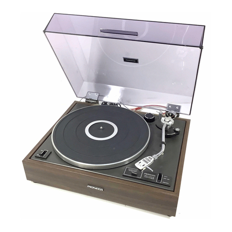
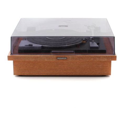
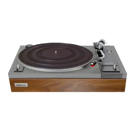
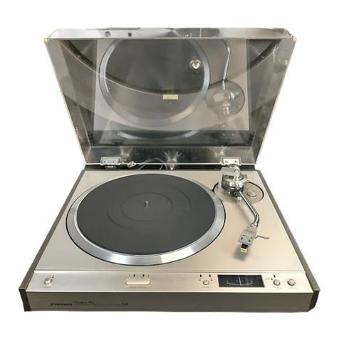
Pioneer PL-71 User manual

DIRECT
DRIVE
STEREO
TURNTABLE
PL-71
OPERATING
INSTRUCTIONS
ey
{|
ay
as
este
Tend
Rae
SRE
SRE
ae
eee
eee
Ree
eee
eels
ed
oleae
fe
Wed
oe
hod
eo
fete
ee
I
ee
ee
Wel
es
eT
Tet
ee ee
ee ee
ET
EA
peed
Wetec)
Wet
Mee
sd!
@MpwoneeR|
|
||
|
|
|
Reza
eee
eee
REE
ee
—
nas
ae
ex
Es
ae
=|

Thank
you
very
much
for
your
purchase
of
Pioneer
model
PL-71.
You
will
get
many
years
of
pleasure
from
this
top-quality
stereo
turntable.
To
get
the
most
from
this
feature-packed
turntable,
please
read
the
operating
instructions
and
follow
the
directions
indicated.
For
the
psychological
benefit
of
those
who
still
want
to
use
their
optional
phono
cartridges,
no
phono
cartridge
is
equipped
with
this
turntable.
The
first
thing
you
have
to
do
is
to
attach
your
option
to
a
head
shell
referring
to
the
directions
indicated
in
the
instructions.
FEATURES
DIRECT
DRIVE
SYSTEM
No
belt
or
idlers.
The
DC
servo
motor
drives
the
platter
directly,
resulting
in
lowest
possible
vibrations
transmitted
to
the
tonearm.
The
result
is
a
new
height
of
turntable
performance
plenty
for
the
most
demanding
audio
en-
thusiast.
ELECTRONIC
SERVO
CONTROL
Turntable
revolution
speed
is
affected
by
many
factors,
including
ambient
room
temperature,
etc.,
which
cannot
be
predicted
or
corrected
by
motor
performance
alone.
This
electronic
circuit
comes
into
play
at
the
touch
of
a
button,
letting
you
adjust
the
speed
+2%
during
either
33-1/3
or
45
rpm
play.
PRECISION
TRACKING,
SENSITIVE
ANTI-SKATING
SYSTEM
Playing
4-channel
records
requires
extra
tonearm
precision,
and
the
PL-71
delivers.
Not
only
with
an
exactly-balanced
tonearm
design,
but
also
with
an
ideal
anti-skating
system.
The
result
is
stable
tracking
over
every
part
of
the
record
for
brilliant
response
from
the
first
note
to
the
last.
CONVENIENT
AUXILIARY
FEATURES
The
tonearm
is
raised
and
lowered
by
ARM
ELEVATOR,
saving
both
stylus
and
record
wear.
The
stylus
overhang
can
be
adjusted
precisely
with
the
overhang
gauge.
The
semitransparent
dust
cover
is
held
by
spring-loaded
hinges
and
can
be
arrested
in
any
desired
position.
If
de-
sired,
it
can
be
removed
altogether.
EYE-APPEAL
DESIGN
The
cabinet
is
set
off
the
natural
beauty
of
selected
walnut,
with
a
smart
black
base
plate.
All
controls
are
grouped
on
the
right
for
easy
one-hand
operation.
CONTENTS
Features
Installation
Stereo
System
Setup
Assembly
Adjustments
Parts
Identification
Operation
Stereo
Amplifier
Connection
Precautions
Line
Voltage
Troubleshooting
Specifications
INSTALLATION
Install
the
PL-71
with
the
following
points
in
mind.
The
place
must
be
well-ventilated
and
free
from
humidity
and
dust.
The
unit
should
not
be
exposed
to
direct
sun-
light.
The
unit
should
be
placed
on
horizontal
situa-
tion.
The
unit
should
be
placed
as
far
from
the
speaker
systems
as
possible.
2

STEREO
SYSTEM
SETUP
The
PL-71
is
a
first-quality
stereo
turntable
and
can
provide
its
full
performance
only
when
com-
bined
with
other
components
of
equal
quality,
so
you
should
select
other
quality
components
com-
parable
to
this
turntable.
Set
up
the
system
as
shown
in
Figs.
1
or
2.
A
WORD
ABOUT
COMPONENTS
Be
sure
to
select
the
rest
of
your
system
with
an
eye
to
achieving
sufficient
performance
and
re-
sponse
so
that
you
can
make
the
most
of
your
PL-71.
A
wise
choice
would
be
the
Pioneer
components
designed
and
manufactured
to
provide
these
very
characteristics.
The
Amplifier
There
are
many
types
available:
Integrated
stereo
amplifiers,
AM/FM
stereo
receiver,
stereo
pream-
plifiers
and
stereo
power
amplifiers.
You
can
take
your
choice
of
systems,
making
sure
the
one
you
choose
will
blend
well
with
the
speakers
you
select.
Look
for
high
performance
and
stability
in
an
amplifier.
The
Speakers
Here
there
are
also
many
possibilities.
You
have
a
choice
or
bass-reflex
type
or
fully-enclosed
type
cabinets,
full-range,
2-way,
3-way
and
other
types
of
speaker
component
combinations,
and
book-
shelf,
floor
type
or
omnidirectional,
etc.
styling.
With
all
these
choices,
your
main
guide
should
be
how
well
speakers
sound
with
the
rest
of
your
system.
The
Phono
Cartridge
There
are
magnetic
(moving
coil,
moving
magnet
and
induced
magnet
types)
cartridge
as
well
as
semi-conductor
types
and
optical
types.
If
you
use
a
moving
coil
(MC)
type
cartridge
with
the
PL-71,
make
sure
your
amplifier
has
the
capa-
bility
of
accepting
this
type
of
input
signal.
PIONCER
PL-71
STEREO
AMPLIFIER
SPEAKER
SYSTEMS
Fig.
1
PL-71
©O00O?O]|
STEREO
9
2999
0909
PREAMPLIFIER
STEREO
POWER
AMPLIFIER
SPEAKER
SYSTEMS
Fig.
2

ASSEMBLY
To
avoid
possible
damage
during
transport,
heavy
parts
(such
as
the
platter)
and
delicate
ones
are
packed
separately
from
the
main
body.
Assemble
them
into
one
unit
as
shown
in
the
illustrations.
REMOVE
THE
TONEARM
PACKING
Gently
remove
the
tonearm
packing
as
shown
in
Fig.
3.
PLATTER
INSTALLATION
Remove
the
platter
from
its
separate
package
and
slip
it
onto
the
center
shaft.
Then
place
the
rubber
mat
on
the
turntable
platter.
CARTRIDGE
MOUNTING
The
color-coded
pin
connectors
in
the
head
shell
conform
to
the
international
EIA
standard.
Attach
the
cartridge
according
to
the
drawing
(Fig.
4).
After
connection
of
»in
connectors,
plug
the
head
shell
into
the
tonearm
and
tighten
firmly
locking
collar
(Fig.
5).
OVERHANG
ADJUSTMENT
After
mounting
the
cartridge,
you
must
adjust
overhang
length.
At
first,
set
the
45
rpm
record
adaptor
provided
with
overhang
gauge
onto
the
center
shaft.
Bring
the
head
shell
to
the
point
of
the
overhang
gauge
and
regulate
stylus
tip
to
14.5
mm
index
line
explained
in
Figs.
6
and
7.
When
overhang
adjustment
is
over,
tighten
the
cartridge-held
screws.
HOW
TO
ADJUST
OVERHANG
OVERHANG
CHECKER
Fig.
7
TONEARM
PACKING
A
TAKE
OUT
Fig.
3
ena
WASHERS
|
*
WHITE
(+)
oL
RED
(+)
R
S
eee”
BLUE
(-)
L
CARTRIDGE
SW
MEAD
SHELL
GREEN
(-)
R
a
Sa
This
illustrates
use
of
Pioneer
cartridge
PC-50.
Fig.
4
LOCKING
COLLAR
Fig.
5
45
rpm
ADAPTOR
(OVERHANG
GAUGE)
Adjust
cartridge
so
that
the
stylus
comes
right
over
this
index
line
of
14.5
mm.
Fig.
6

COUNTERWEIGHT
INSTALLATION
Counterweight
consists
weightsleeve
and
main
weight.
At
first,
the
weightsleeve
slips
into
the
rear
end
of
the
tonearm
(Fig.
8).
Once
it
is
slipped
on
a
bit
the
threads
will
engage.
Screw
on
more
turning
in
a
clockwise
direction
a
few
times.
Next,
the
main
weight
slips
into
the
rear
end
of
the
weightsleeve
and
tighten
weight-fasten
screw
so
the
clearance
cound
be
made
3
mm
between
main
weight
and
weightsleeve
(Fig.
9).
LATERAL
WEIGHT
INSTALLATION
Install
the
lateral
weight
as
follows:
1.
Loosen
the
screw
which
holds
the
lateral
crooked
bar
on
the
tonearm.
2.
Slip the
lateral
weight
stored
in
accessory
box
into
the
lateral
crooked
bar,
then
tighten
the
fitting
screw
of
lateral
weight
(Fig.
10).
3.
Tighten
the
lateral
crooked
bar-held
screw
so
that
the
lateral
crooked
bar
is
kept
vertically
against
the
tonearm
pipe.
NOTE:
The
lower
the
lateral
weight
is
installed,
the
lower
the
center
of
gravity
becomes.
The
higher
the
lateral
weight
is
installed,
the
higher
the
center
of
gravity
becomes.
This
is
called
“variable
center-of-gravity
type
lateral
balance.”*
THE
HEIGHT
OF
THE
ARM
REST
ADJUSTMENT
The
height
of
the
arm
rest
can
be
adjusted
by
untightening
the
fitting
screw
(Fig.
11).
ADJUSTMENT
OF
TONEARM
HEIGHT
The
height
of
the
tonearm
must
be
kept
parallel
with
turntable
platter.
This
height
can
be
regulated
by
untightening
2
clamp
screws
as
shown
in
Fig.
12.
Fig.
12
a
a
a
a
ee
ENE
eR
Rn
eat
fh
(
INIC-
WEIGHTSLEEVE
TONEARM
WEIGHT-FASTEN
SCREW
Fig.
9
LATERAL
CROOKED
BAR-HELD
SCREW
LATERAL
CROOKED
BAR
Fig.
10
ARM
REST
~
\
)
alt
¥;
~-SCREWDRIVER
.
Fig.
11

ADJUSTMENTS
HORIZONTAL
BALANCE
ADJUSTMENT
1.
Set
the
anti-skating
force
control
knob
to
the
“6.
2.
Remove
the
stylus
protection
cover
from
the
cartridge.
.
Free
the
tonearm
from
the
arm
rest.
.
Bring
down
the
arm
elevator.
.
Move
the
weight
sleeve
slowly
back
and
forth
(by
turning
it)
until
the
tonearm
floats
in
hori-
zontal
position.
6.
Keeping
the
weight
sleeve
in
this
position,
turn
only
the
tracking
force
dial
ring
so
that
the
zero
aligns
with
the
black
index
line
on
the
tonearm.
(Fig.
13).
7.
After
the
horizontal
balance
is
complete,
return
the
tonearm
to
the
arm
rest
and
clamp
it.
TRACKING
FORCE
ADJUSTMENT
After
the
horizontal
balance
adjustment
is
com-
plete,
the
tonearm
is
at
zero
tracking
force.
Turn
the
weight
sleeve
(the
tracking
force
dial
ring
and
main
weight
will
turn
with
it)
until
the
gauge
reads
the
correct
force
for
the
cartridge
(Fig.
14).
ANTI-SKATING
ADJUSTMENT
The
anti-skating
force
control
knob
should
be
adjusted
to
the
same
setting
as
that
required
for
the
tracking
force
(Fig.
15).
What
is
“Anti-skating”’?
A
force
is
created
by
the
record
rotation
which
tends
to
pull
the
stylus
(and
tonearm)
toward
the
center
of
record.
The
anti-skating
device
provides
a
precisely
controlled
counter
force
to
cancel
this
tendency.
LATERAL
BALANCE
ADJUSTMENT
Adjust
the
lateral
bar
length
as
shown
in
Fig.
16,
so
that
the
lateral
bar
length
become
from
20
to
24
mm.
om
©
NOTE:
After
this
adjustment
once
made,
no
readjustment
is
needed
even
if
the
supplied
phono
cartridge
is
replaced
with
your
option.
Installation
of
the
Cartridge
It
is
possible
for
this
tonearm
to
install
a
cartridge
of
which
weight
is
4
to
32g
by
positioning
the
main
weight
on
the
weightsleeve.
In
using
almost
all
the
cartridge
on
the
mar-
ket,
this
tonearm
will
be
adjusted
by
above-stated
way.
But
only
when
using
extremely
heavy
or
light
cartridge,
tonearm
adjustment
may
be
impossible.
In
such
a
case,
untighten
the
weight
fasten
screw,
then,
slide
the
main
weight
back
and
forth.
TRACKING
FORCE
DIAL
RING
~
ANTI
SKATING
FORCE
CONTROL
KNOB
Fig.
13
WEIGHTSLEEVE
MAIN
WEIGHT
TRACKING
FORCE
DIAL
RING
INDEX
LINE
The
gauge
is
graduated
between
0.5
and
3.0
grams.
Fig.
14
ANTI
SKATING
FORCE
CONTROL
KNOB
For
example,
if
the
tracking
force
of
the
cartridge
is
2
grams,
set
the
anti-skating
force
control
knob
to
2.
Fig.
15
<~LATERAL
WEIGHT
LATERAL
CROOKED
BAR
“LAT
ERAL
CROOKED
BAR-HELD
SCREW
Fig.
16
Corresponding
relation
of
the
cartridge
weight
and
the
clearance
is
shown
as
below:
Cartridge
weight
Proper
clearance
—
0
a
3
mm
7
25
g
15
mm
32
20
mm

PARTS
IDENTIFICATION
DUST
COVER
STROBOSCOPE
COUNTERWEIGHT
LATERAL
WEIGHT
~
ARM
REST
TONEARM
y
STROBOLIGHT
CARTRIOGE
MOUNTING
SCREWS
DUST
COVER
ATTACHMENT
Slip
the
hinges
on
the
plastic
dust
cover
into
their
|
counterparts
on
the
cabinet.
Be
sure
to
press
the
two
sets
of
hinges
together
firmly
(Fig.
17).
MAIN
WEIGHT
TURNTABLE
PLATTER
WEIGHTSLEEVE
CENTER
SHAFT
pi
Le
PIONEER
45
rpm
ADAPTOR
(
OVERHANG
GAUGE
)
LATERAL
WEIGHT
HEAD
SHELL
CARTRIDGE
MOUNTING
NUTS
WEIGHT
PLATE

PARTS
AND
THEIR
FUNCTIONS
STROBOSCOPE
The
proper
part
of
the
stroboscope
band
to
read
illuminated
by
the
strobolight
depends
upon
the
frequency
of
the
power
sources
and
record
speeds
as
below.
33-1/3
rpm
45
rpm
STROBOLIGHT
ARM
REST
The
tonearm
should
be
on
the
arm
rest
whenever
the
turntable
is
not
in
use.
If
the
unit
is
to
be
moved
or
transported,
first
secure
the
tonearm
to
the
arm
rest
with
the
built-in
clamp.
ARM
REST
OPERATION
The
operation
is
very
simple
about
playing
records
on
the
PL-71
once
you
are
accustomed
to
the
operation.
Simply
follow
these
steps:
1.
Place
a
record
on
the
platter.
2.
Remove
the
stylus
protector
from
the
cartridge
and
free
the
tonearm
from
the
rest
clamp.
3.
Push
the
33-1/3
RPM
BUTTON
or
45
RPM
BUTTON.
This
operation
will
simultaneously
cause
the
turntable
platter
to
rotate.
4.
Watch
the
proper
stroboscope
band
running
illuminated
by
the
strobolight.
Adjust
the
speed
with
the
speed
control
as
explained
above.
5.
When
the
proper
stroboscope
appears
to
stand
still,
move
the
tonearm
so
that
the
stylus
is
directly
in
the
starting
point
of
the
record.
SPEED
CONTROL
KNOBS
With
either
of
the
speed
selectors
pressed,
watch
the
appropriate
stroboscope
band
and
strobolight.
Adjust
the
precise
speed
(so
that
the
band
appears
to
stand
still)
by
turning
the
speed
control
knobs.
Turn
toward
+
(clockwise)
for
faster
speed,
toward
—
(counterclockwise)
for
slower.
When
the
strobo-
scope
appears
to
stand
still,
the
speed
is
correct.
S7GRD
GSDNAGL,
SPEED
CONTROL
KNOB
45
rpm
|
—~
33-1/3
rpm
6.
Move
the
ARM
ELEVATOR
down.
The
tonearm
will
be
gently
lowered
onto
the
record,
then
the
performance
will
begin.
7.
If
you
wish
to
start
playing
in
the
middle,
simply
move
the
ARM
ELEVATOR
upward.
8.
After
the
record
has
been
played,
move
the
ARM
ELEVATOR
up
and
return
the
tonearm
to
the
arm
rest.
9.
When
the
performance
is
over,
the
POWER
OFF
switch
must
be
pushed
immediately.
HOW
TO
USE
THE
ARM
ELEVATOR
The
arm
elevator
is
particularly
convenient
when
you
wish
to
choose
your
favorite
music
or
songs
from
the
several
songs
recorded
on
the
same
side
of
an
LP
record.

es
LO
ES
45
RPM
BUTTON
a
ARM
ELEVATOR
Push
this
button
for
playing
a
45
rpm
speed
re-
cord,
Simultaneously
the
power
will
be
turned
on.
33-1/3
RPM
BUTTON
Push
this
button
for
playing
a
33-1/3
rpm
speed
record.
Simultaneously
the
power
will
be
turned
on.
[ONES
BE
EO)
45
rpm
33-1/3
rpm
———
POWER
“OFF”
SWITCH
Push
this
button
for
turning
off.
POWER
“OFF”
SWITCH
FQMEACTAR
)
#@
PIONEER
amor
Gm
This
is
a
lever
for
controlling
the
up-and-down
movement
of
the
tonearm.
Setting
the
ARM
ELEVATOR
up,
the
arm
head
will
be
floated
from
the
surface
of
the
record.
Setting
the
ARM
ELEVATOR
down,
the
arm
head
will
be
quietly
descended
on
the
surface
of
the
record.
This
is
a
convenient
device
for
cueing
in
any
portion
of
the
record
without
fear
of
scratching
the
record
surface.
STEREO
AMPLIFIER
CONNECTIONS
1.
The
connection
cords
of
the
PL-71
are
marked
L
and
R;
connect
them
to
the
stereo
amplifier
left
and
right
PHONO
MAG
terminals
(Fig.
18).
2.
The
cord
provided
with
spare
lugs
is
the
ground
wire.
Firmly
connect
it
to
the
GND
or
E
ter-
minal
of
the
amplifier.
NOTES:
1.
When
employing
a
low
level
moving
coil
(MC)
type
cartridge,
use
a
step-up
transformer
or
a
stereo
am-
plifier
equipped
with
an
input
terminal
for
a
moving
coil
cartridge.
2.
When
a
non-standard
cartridge
is
to
be
used,
make
am-
plifier
connections
according
to
instructions
which
come
with
the
cartridge.
L
CHANNEL
onge
ol
s5>
.
0
RG
R
CHANNEL

ae
I
ANE
EN
EE
DI
A
A
PRECAUTIONS
NO
VIBRATION
The
tracking
force
of
your
stylus
will
probably
be
extremely
light,
so
it
is
important
to
place
the
unit
in
a
location
protected
from
vibrations.
This
is
another
reason
why
it
should
not
be
too
close
to
the
speakers.
DO
NOT
OPEN
THE
SET
OR
TOUCH
THE
INSIDE
PARTS
Your
PL-71
is
assembled
with
a
number
of
small
and
delicate
components
into
one
precision
mecha-
nism
which
should
not
be
touched.
There
is
no
reason
to
open
the
unit
or
remove
the
turntable
once
assembly
is
complete.
NO
LUBRICATION
There
is
no
use
to
lubricate
this
model
because
of
the
use
of
oilless
bearings
in
the
rotating
parts.
ALWAYS
CLEAN
THE
STYLUS
e
If
the
stylus
is
dirty,
sound
quality
will
deterio-
rate.
Brush
it
off
with
a
soft
brush
from
time
to
time.
e
If
the
record
surface
is
dirty,
clean
it
with
a
record
cleaner
before
playing.
e
It
is
preferable
to
make
it
a
habit
to
clean
a
record
surface
before
each
play.
e
Touching
the
stylus
with
a
finger
is
a
common
cause
of
stylus
damage,
so
be
very
careful
when
handling
the
tonearm
and
when
cleaning
it.
CHOOSE
A
LEVEL
LOCATION
If
the
unit
is
not
level
various
performance
problems
will
occur,
so
play
careful
attention
to
this
point.
LINE
VOLTAGE
Be
careful
of
line
voltage.
Your
PL-71
is
possible
to
operate
on
five
kinds
of
voltage.
The
turntable
is,
of
cource,
factory-adjusted
for
the
local
line
voltage
of
the
country
to
which
it is
being
shipped.
If
you
use
the
unit
in
the
different
country
or
area
from
where
you
bought
it,
please
confirm
if
the
local
line
voltage
is
the
same
as
at
place
you
bought
it.
The
line
voltage
of
the
unit
can
be
adjusted
by
the
LINE
VOLTAGE
SELECTOR
PLUG
that
provided
inside
the
wooden
base.
You
can
regulate
the
line
voltage
for
operation
by
yourself
as
follows:
1.
Unscrew
a
total
of
10
bottom
plate-held
screws
as
shown
in
Fig.
19.
2.
Remove
the
bottom
plate,
and
you
can
find
the
LINE
VOLTAGE
SELECTOR
PLUG.
3.The
cut-off
of
the
selector
plug
shows
the
voltage
which
operate
the
unit.
(Perhaps,
it
ought
to
be
different
from
your
local
line
voltage.)
4.
Pull
out
the
selector
plug,
and
put
it
back
as
indicated
in
cut-off
your
house
voltage
110V,
120V,130V,
220V
or
240V.
(Fig.
20).
10
©:
"il
Il
I
Ma
wl
To
remove
bottom
plate,
unscrew
a
total
of
10
screws.
Fig.
19
LINE
VOLTAGE
SELECTOR
PLUG
Insert
selector
plug
so
that
correct
voltage
figure
is
visible
in
cut-off.
Fig.
20

eg
a
EE
FEC
Cie
TROUBLESHOOTING
HUM
“HUM”
is
a
low-pitch
droning
noise,
often
60
or
50Hz,
resulting
from
a
loose
connection
of
the
ground
lead.
If
hum
occurs:
e
Check
the
connection
of
the
PL-71
running
near
the
power
transformer
of
your
amplifier.
Chang-
ing
the
connection
of
the
PL-71
in
relation
to
the
amplifier
will
often
eliminate
hum.
e
Check
the
connection
of
the
PL-71
ground
lead
(the
black
lead
with
a
split
lug)
to
your
amplifier.
If
it
is
loose,
connect
firmly.
e
Reversing
of
the
AC
cord
may
occasionally
eliminate
hum.
HOWLING
“HOWLING”
is
acoustical
feedback
from
speakers
to
the
tumtable
unit.
Increasing
the
distance
between
the
speakers
and
the
turntable,
or
even
better,
laying
a
soft
cushion
under
the
turntable
will
eliminate
howling.
SPECIFICATIONS
Phono
Motor
and
Turntable
Motor.
66
keeles
Brushless
DC
servo
Direct-drive
motor
SDGCU
oo
vs
vice.
sveisie’
wis
ewes
Two
speeds:
33-1/3,
45rpm
Wow
and
Flutter
...............
0.05%
(WRMS)
or
less
SIN
us
aide
nteaie
e702
60dB
or
more
(in
case
of
using
Pioneer
cartridge
model
PC-50)
Turntable
platter
..
0...
,
31cm
diam.
Aluminum
alloy
Tonearm
Tonearm
type
.........
Static
balance,
S-shape,
pipe
arm
Effective
armlength
..................0...
224mm
OVE
ANG:
5
sis.
c00
aie
a
hse
eve
ds
wd
ote
Shae
whales
14.5mm
Usable
cartridge
weight
........
4g
(MIN)
to
32g
(MAX)
Subfunctions
Anti-skating
force
control
Lateral
balancer
Hinges
(Free-adjustable)
Large-size
shock
absorbers
Arm
elevator
Height-adjustable
arm
rest
Speed
fine
adjusters
(33-1/3rpm,
45
rpm:
for
use
in
turntable
speed
adjustment
with
stroboscope
and
strobo-
light)
a
eee
Others
Power
requirements
.........
AC
110,
120,
130,
220
and
240V,
60
or
SOHz
Power
consumption
.............0.e0005
5.2W
(MAX)
Outer
dimensions
......
480
(W)
x
410(D)
x
185(H)
mm
18-7/8
(W)
x16-1/8(D)
x
7-1/4(H)
in.
Weights
ois
nad
sa
iace
aro:
aie
aac
ieee
vw
are
11.0kg,
24
Ib
30z
Accessory
Group
4Srpm
adaptor
(with
overhang
gauge)
...............
1
SCIOWOTIVER
55
Ses
sy.
ioce
seid
votre
Sadie
Re
caste
one
1
Output
cord
(Connection
cord)
........
0.
cece
eceuee
1
Weight
plate
(Cartridge
weight-adjustable)............
1
Cartridge
mounting
screws...
2.2.2...
00.
ccceeeceees
10
Cartridge
mounting
washers
................00-0000,
2
Cartridge
mounting
nuts
............00.eceeeeeeee
2
Operating
instructions
...
2.2.2.0...
cece
ee
ece
eee
2
NOTE:
Specifications
and
the
design
subject
to
possible
modifica-
tion
without
notice
due
to
improvements.
11

<74K01FO5E>
PIONEER
ELECTRONIC
CORPORATION
4-1,
1-Chome,
Meguro,
Meguro-ku,
Tokyo
153,
Japan
U.S.
PIONEER
ELECTRONICS
CORPORATION
7S
Oxford
Orive,
Moonachie,
New
Jersey
07074,U.S.A.
PIONEER
ELECTRONIC
(EUROPE)
N.V.
Meir-Center
Meir
21,
2000
Antwerp,
Belgium
;
PIONEER
ELECTRONICS
AUSTRALIA
PTY.
LTD.
<PRB-006-0>
Printed
in
Japan
256-8
City
Road,
South
Melbourne,
Victoria
3205,
Australia
Other manuals for PL-71
2
Other Pioneer Turntable manuals

Pioneer
Pioneer PL-510A User manual

Pioneer
Pioneer PL-100 User manual

Pioneer
Pioneer PLX-1000 User manual

Pioneer
Pioneer PL-44F User manual

Pioneer
Pioneer PL-88F User manual

Pioneer
Pioneer PL-A35 User manual

Pioneer
Pioneer PL-510 User manual

Pioneer
Pioneer PL-570 User manual

Pioneer
Pioneer PL-Z93 User manual

Pioneer
Pioneer PLX-1000 User manual

Pioneer
Pioneer PL-12E PV User manual

Pioneer
Pioneer XDJ-1000 User manual

Pioneer
Pioneer PL-670 User manual

Pioneer
Pioneer PL-100 User manual

Pioneer
Pioneer pl-930 User manual

Pioneer
Pioneer BDP-170 User manual

Pioneer
Pioneer PL-530 User manual

Pioneer
Pioneer PL-55DX User manual

Pioneer
Pioneer PL-12D User manual
Pioneer
Pioneer PL-5 User manual