DuraPlane Trainer 40 User manual

DuraPlane
Champaign, IL
(217) 398-8970, Ext. 5
productsupport@duraplane.com
Assembly Instructions
Specifications:
Wingspan: 50 in (1270 mm) Weight: 5.25 lb (2380 g)
Wing Area: 500 sq in (32.3 sq dm) Engine Required: High-performance
Fuselage Length: 44 in (1117.6 mm) 2-stroke .40 to .46 cu in (6.5-7.5 cc) or
Radio Required: 4-Channel with 4 servos 4-stroke .48 to .51 cu in (7.86cc)
READ THROUGH THIS INSTRUCTION MANUAL BEFORE BEGINNING ASSEMBLY. IT CONTAINS
IMPORTANT INSTRUCTIONS AND WARNINGS CONCERNING THE ASSEMBLY AND OPERATION OF
THIS MODEL.
ENTIRE CONTENTS © Copyright 2003
Printed in USA DT40P03 for DURA1111 v1.1

The Trainer 40 is a great “dual purpose” model because it's
extra durable and simple to build for a beginner, and it builds
fast so experienced modelers can quickly get something in
the air if their primary model is out of commission. After you
move on to a fully aerobatic sport model, or get your best
model back into the air, the trusty Trainer 40 will still be
waiting in the wings for you to take it out and get in a few
relaxing flights. The “low risk” factor of the inexpensive, quick
building DuraPlane series makes them great test beds for
new radio equipment or breaking in new engines. Besides all
that, the Trainer 40 flies great and we're sure you'll enjoy lots
of smooth takeoffs and landings!
If this is your first model, the best way to learn to fly R/C is
to join a flying club. The Academy of Model Aeronautics is
the national organization that charters model clubs,
sanctions competitions and insures flying fields throughout
the United States. We urge you to join the AMA because
membership will bring you flying insurance, a subscription
to Model Aviation magazine and many other benefits. The
AMA will gladly send you membership information and lists
of AMA-chartered clubs in your area where you can seek
the help of experienced modelers.
Academy of Model Aeronautics
5151 East Memorial Drive
Muncie, Indiana 47302-9252
(800) 435-9262
FAX (317) 741-0057
Your hobby shop is also an invaluable place for service,
parts and information that you require. We urge you to
patronize your local hobby dealer – he’s there to help you
enjoy your hobby. Finally, if you have any questions or
comments about your DuraPlane, please write or call us at:
DuraPlane
3002 N. Apollo Dr. Ste. 1
Champaign, IL 61822
Telephone: (217) 398-8970, Ext. 5
Fax: (217) 398-7721
E-mail: [email protected]
DuraPlane guarantees this kit to be free from defects in
both material and workmanship at the date of purchase.
This warranty does not cover any component parts
damaged by use or modification. In no case shall
DuraPlane’s liability exceed the original cost of the
purchased kit. DuraPlane reserves the right to change or
modify this warranty without notice.
This instruction manual provides step-by-step instructions
for assembling the Trainer 40 kit. Assembly of the Trainer
40 consists of eight major steps and must be completed in
the following order:
BUILD THE TAIL FEATHERS.......................Page 3
ASSEMBLE THE FUSELAGE.......................Page 5
RADIO INSTALLATION.................................Page 7
BUILD THE WING.........................................Page 9
COVER THE WING & TAIL SURFACES......Page 11
FINAL ASSEMBLY........................................Page 12
BALANCE THE MODEL................................Page 13
FINAL HOOKUPS & CHECKS......................Page 14
FLYING..........................................................Page 15
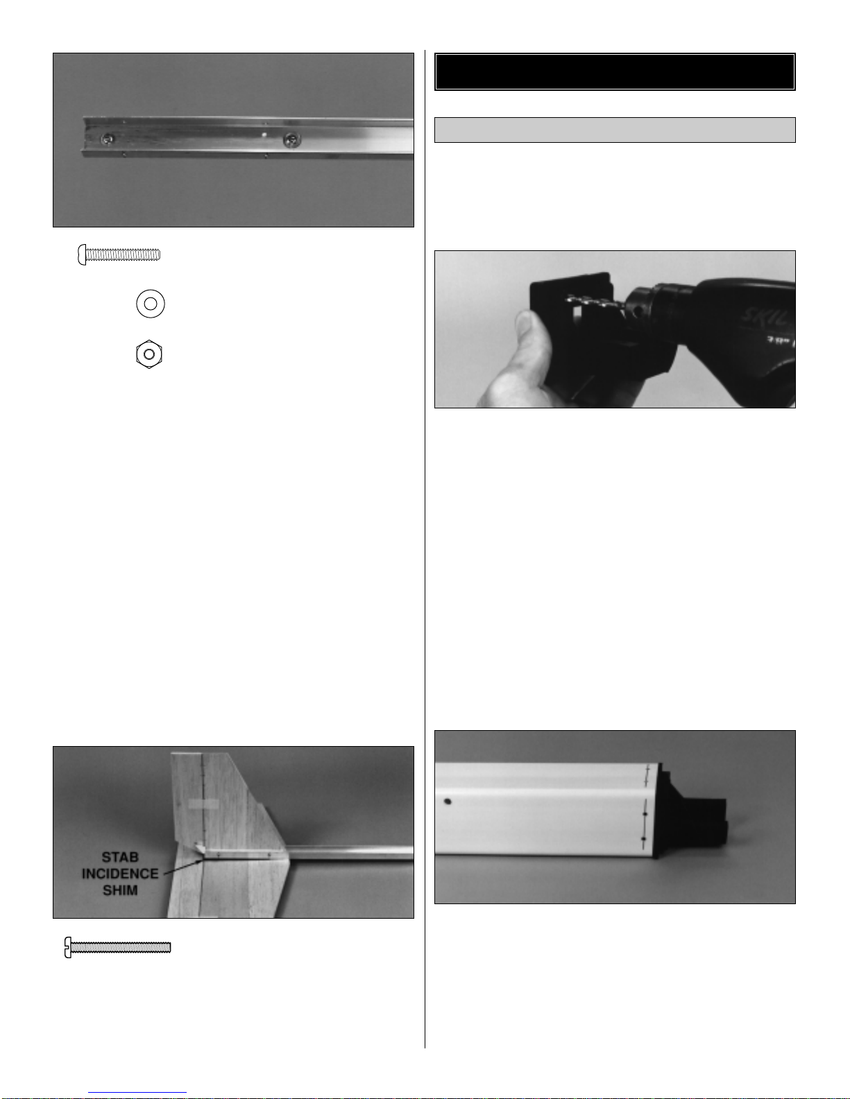
To assemble the Trainer 40, you need the following tools:
❏Flat blade and phillips screwdrivers
❏Small pliers (needle nose)
❏Hobby knife with #11 blades
❏Electric drill
❏Drill bits: 1/16", 7/64", 1/8", 5/32", #18 (or 11/64")
❏Hobby covering iron w/Hot Sock™– optional
(TOPR2175)
❏Sandpaper assortment and sanding block
❏Ruler & felt-tip pen
❏Masking tape
In addition to the parts included with the Trainer 40 kit, you
need the following accessories (we have had good success
using Great Planes®brand Adhesives and Accessory Items):
❏4-channel radio w/4 servos
❏.40-.46 2-stroke or .48 - .51 4-stroke engine w/muffler
❏Propellers (see engine instructions for size)
❏Top Flite®EconoKote®film - (1) roll
❏6-minute epoxy – (GPMR6045)
❏1 oz. thin CA – (GPMR6002)
❏Aliphatic resin (white glue) – optional (GPMR6160)
❏#6 x 3/4" engine mounting screws – (4) (GPMQ3030)
❏2-1/4" spinner (GPMQ4515)
❏8 oz. fuel tank – (GPMQ4103)
❏12" medium silicone fuel tubing – (GPMQ4131)
❏#64 rubber bands – (HCAQ2020)
❏5/32" wheel collars – (2) (GPMQ4306)
❏1/4" foam rubber – (HCAQ1000)
❏2-1/2" wheels – (3) (GPMQ4223)
❏3/4" wide fiberglass reinforced “strapping” tape
❏1/2" double-sided foam mounting tape (GPMQ4440)
❏1/16" x 5/16" wing seating foam tape (GPMQ4422)
❏Loctite®thread lock
Refer to the Parts List for a description of the parts and
hardware included with the Trainer 40 kit.
Accessories & Additional Items
Suggested Tools
Table of Contents
WARNING
Radio control models are intended for adults or use
under the close supervision of an adult. Flying model
airplanes can be dangerous and can cause serious
injury. DuraPlane assumes no responsibility for accidents
or injury caused by this product.
Introduction
2

❏1. Glue the shaped 1/4" balsa Fin Front to the Fin Rear
with medium CA. Use 150-grit sandpaper and a sanding
block to sand the Fin flat and round the leading edge
before proceeding. Glue the 1/4" x 1/2" x 5-7/8" balsa Fin
Base Sides to both sides of the Fin. Make sure that the
bottom of the fin and the bottoms of the fin base sides are
flush. Bevel the front of both fin base sides so they are
even with the LE of the fin.
❏2. Sand the Leading Edge (LE) of the shaped 1/4" balsa
Rudder to a “V” shape to allow for control movement.
Position a nylon Control Horn on the rudder so the bottom
edge of the horn is 7-1/4" below the top of the rudder. Use
the control horn as a template to drill two 1/16" holes for the
2-56 x 1/2" screws. Push the screws through the control
horn. Then thread them into the Control Horn Back Plate
until it is snug.
❏3. Mark the locations of the Hinges on the rudder and
fin as shown in the photo above.
❏4. Use a hobby knife with a #11 blade to cut the hinge slots.
Tip: Carefully move the blade back and forth to enlarge the slot
❏5. Cut the hinges from the 2" x 9" CA Hinge Strip, then
use scissors to snip the corners off. Test fit the hinges to
see if the slots are deep enough.
❏6. Temporarily join the rudder to the fin with three
hinges. Do not glue the hinges in the fin and rudder
until instructed to do so.
1"
1"
3/4"
AND #11 BLADE
WITH HOBBY KNIFE
CUT HINGE SLOT
Trim off the excess
screw threads
Assemble The Fin & Rudder
Build The Tail Feathers
3

❏1. Glue the shaped 1/4" balsa Stab Front to the Stab
Rear with medium CA. Tip: Sand the Stabilizer flat and
even before proceeding. Draw a centerline on the stab and
also on the 1/16" plywood Stabilizer Bottom Plate.
❏2. Align the centerlines. Then glue the stabilizer bottom
plate to the stabilizer. The end of the bottom plate should
be flush with the TE of the stabilizer. See the photo at step 3.
❏3. Sand the leading edge of the 1/4" balsa Elevator to a
“V” shape. Cut four hinge slots in the elevator and stabilizer
at the locations shown in the photo. Without using any
glue, temporarily join the elevator to the stabilizer with
four hinges.
❏4. Draw a line on the top of the elevator 6-7/8" from the
left tip. Align the left edge of a nylon control horn with the
line, then drill two 1/16" holes through the elevator – just
the same as you did on the rudder. Mount the control horn
to the elevator with two 2-56 x 1/2" screws and the back plate.
❏1. Drill two 1/8" holes through both sides of the rear of
the Aluminum Fuselage Channel at the locations shown
in the photo (the rear is the end with the two pre-drilled
smaller holes in the bottom that are closer together). Insert
the fin in the fuselage channel so that the trailing edge is
aligned with the aft edge of the channel. Mark the location
of the holes in the bottom and the sides of the fuselage
channel on the fin. Remove the fin and drill 1/8" holes
through only the marks on the side of the fin.
❏2. Center the black plastic stab incidence shim on the
fuse channel so that the aft edges are aligned. The thickest
part of the shim is the rear. Mark on the shim, the location
of the aft hole in the channel, then drill a 1/8" hole at the
mark in the shim.
❏3. Align the centerline you drew on the stabilizer bottom
plate with the holes in the fuselage channel and mark
their location.
Note: The TE of the stab should be aligned with the end of
the channel. Drill 1/8" holes through the stab at the marks.
Mount The Fin & StabAssemble The Stabilizer & Elevator
4

❏4. Use 6-minute epoxy to glue two 4-40 x 3/4" machine
screws in the bottom rear holes of the fuselage channel.
After the epoxy has cured, temporarily mount the stab to
the fuselage channel with the stab incidence shim, 4-40
screws, #4 washers and two 4-40 nuts.
Note: The bottom of the stab is the side with the 1/16"
plywood stabilizer bottom plate.
❏5. Remove material from the bottom of the fin as
needed to clear the heads of the screws, then temporarily
mount the fin to the fuselage channel with two 4-40 x 1"
machine screws and nuts.
❏1. Test fit your engine to the engine mount. If the engine
does not fit perfectly into the mount use a Dremel®
MultiPro™or a file to carefully grind away the plastic until
your engine drops into the mount.
❏2. Determine the location where the throttle pushrod will
exit the firewall portion of the engine mount so it will align
with the carburetor arm on your engine. For most engines
the molded-in hole on the upper right side of the mount is
close enough. Enlarge this hole with a 3/16" drill all the
way through the mount. If you decide to drill the hole in a
different location make sure the throttle pushrod will not
interfere with the fuel tank.
❏3. Place the engine on the mount, then mark the
location of the engine mounting holes. Drill 7/64" holes for
mounting the engine with #6 x 3/4" screws and washers
(not included). Some modelers prefer to drill and tap the
holes for 4-40 x 3/4" machine screws (not included)
instead. Use a #43 drill if you choose to tap threads for
4-40 screws.
❏4. Use a felt-tip pen to draw a line on the sides, top and
bottom of the fuselage 5/16" from the front edge. Fit the
engine mount into the fuselage, then drill two 7/64" holes,
evenly spaced, through the four sides of the fuselage and
the engine mount on the lines you drew. Make sure that
you do not drill the holes in a location that will interfere with
the throttle pushrod. Remove the mount, then enlarge the
holes in the fuselage only with a 9/64" drill.
Install the Engine Mount & Fuel Tank
Assemble the Fuselage
4-40 x 1" Machine Screw
4-40 Hex Nut
#4 Flat Washer
4-40 x 3/4" Machine Screw
5

❏5. Assemble a Great Planes 8 oz. fuel tank according to
the instructions included with the tank. Then install 6" of
medium fuel line on the fill and vent tubes. Cut a piece of
1/4" foam to a size of 3" x 8" and place it inside the front of
the fuselage about 1" back from the front edge. Slide the
tank into the foam inside the front of the fuselage. Mount
the engine mount to the fuselage with eight #6 x 3/4"
screws included with this kit, then slide the 12" long throttle
pushrod guide tube into the hole you drilled through the
firewall and past the fuel tank. Slide the 12" long throttle
pushrod into the guide tube. Mount the engine onto the
engine mount.
❏6. Place the fuselage on its side and use a 90-degree
triangle or a builder’s square to mark a line centered on the
forward hole in the bottom of the fuselage. Draw a line
across the center of each 1/4" plywood landing gear plate.
❏7. Fit a 8-32 x 1/2" screw through the hole in the center
of the aluminum landing gear and the forward hole in the
bottom of the fuselage. Align the outer holes in the landing
gear with the line you drew, then mark the locations of the
holes onto the fuselage bottom. Remove the landing gear,
then drill a 7/64" hole through the marks. Use coarse
sandpaper and a sanding block to round a bottom corner of
each landing gear plate so it will fit the curve inside the
fuselage. The bottom of the plates is the side with the line
you drew. Place one of the landing gear plates inside the
fuselage so the line is visible through one of the holes you
drilled, then mark the location of the hole on the landing
gear plate. Drill a 7/64" hole at the mark. Position, mark,
then drill a 7/64" hole through the other landing gear plate.
Mount the landing gear to the fuselage with the landing
gear plates and two #6 x 1/2" screws supplied with this kit.
The wood landing gear plates do not need to be glued to
the fuselage.
❏8. Remove the engine from the engine mount. Then
mount the wire nose gear to the engine mount with three
5/32" wheel collars and 6-32 x 1/4" screws included with
this kit. Insert one of the wheel collars into the nylon
steering arm. Arrange the wheel collars and temporarily
tighten the screws so the fuselage is level when sitting on
your workbench.
❏9. Drill the hub of the 2-1/2" main wheels with a #18 (or
11/64") drill, then fit a 8-32 x 1-1/4" “axle” into one of the
wheels and thread on a 8-32 nut. Screw the axle with the
wheel and nut onto the landing gear and secure it with
another 8-32 nut and a drop of thread lock. Mount the other
wheel to the landing gear in the same manner.
❏10. Mount the front 2-1/2" wheel to the nose gear with a
5/32" wheel collar (not supplied) on both sides of the wheel.
Mount The Landing Gear
6

❏11. Set the fuselage on your work bench and readjust
the wheel collars on the nose gear so the fuselage is level.
Secure the 6-32 screws in the wheel collars with a drop of
thread lock.
❏1. Use 6-minute epoxy to glue two 6-32 x 1/2" machine
screws in the front holes in the fuselage channel. Insert the
screws from inside the channel just like you did the 4-40
screws in the rear of the channel for the stab.
❏2. Insert three servos into the fuselage channel in the
orientation shown in the sketch. The front servo should be
approximately 3" from the front of the channel but should
not interfere with the 6-32 screw you glued in the channel.
The other servos should be behind the front servo but not
contacting each other.
❏3. Temporarily connect the servos and a battery pack to
the receiver. Then turn on the receiver and transmitter to
center the servos. Place a servo arm on each servo in the
orientation shown in the sketch, then turn off the system
and disconnect the servos.
❏4. Mount the receiver to the fuselage channel behind the
rear servo. There are a few ways to mount the receiver but
the most secure way, and the recommended way is to make
a receiver plate from a piece of 1/8" “lite-ply” and a piece of
3/4" wide balsa (not supplied). Glue the receiver plate (the
approximate size of the base of the receiver) to the balsa
block, then fit the block in the fuselage channel like you did
the servos. Mount the receiver to the plate with 1/4" of foam
in between the receiver and the plate. Make sure this
arrangement will clear the rear 1/4" wing dowel when it is
time to mount the fuselage channel to the fuselage.
❏1. Thread a nylon clevis onto a 1" threaded stud about
20 turns, then thread the other end of the threaded stud
about 1/2" into a 24" long Inner Pushrod Tube. Connect
the clevis to the control horn on the elevator. Route the
inner pushrod tube over the receiver and place it on top of
the elevator servo (middle servo) arm. Cut the inner
pushrod tube 7/8" short of the servo arm.
❏2. Cut a 24" Outer Pushrod Tube 2" shorter than the
inner pushrod and slide it over the tube. Thread another
clevis onto a threaded stud, then thread it into the inner
pushrod just the same as you did on the other end.
Temporarily connect the clevis to the servo.
Threaded Stud
Connect The Elevator & Rudder
Pushrods
RECEIVER
RUDDER
SERVO
THROTTLE
SERVO
ELEVATOR
SERVO
FUSE
CHANNEL
RX
BATTERY
FRONT
Install the Servos
Radio Installation
7

❏3. Perform the same operation for the rudder with the
same hardware you used for the elevator.
❏4. Secure the front end of the elevator and rudder outer
pushrod tubes by taping them directly to the receiver.
Tip: Place a 3/16" x 7/8" x 1-1/2" balsa block (not included)
between the pushrods.
❏5. Temporarily tape the aft end of the outer pushrod
tubes to the fuselage channel in the area about 1" ahead of
the stabilizer.
❏1. Connect a clevis using a 1" threaded stud to one of
the 12" throttle pushrod. Slide the pushrod into the throttle
outer guide tube from inside the fuselage.
❏2. Temporarily mount the fuselage channel to the
fuselage with a 6-32 nut on both of the 6-32 screws you
glued to the channel. Mount the engine if you have not
already done so.
❏3. Connect the clevis on the throttle pushrod to the
throttle servo arm. Thread a 1" threaded stud onto a clevis,
then temporarily connect the clevis to the arm on the
carburetor. When the clevis and the threaded stud are
connected to the carburetor, you can see where to cut the
outer guide tube and the throttle pushrod. Cut the tube and
pushrod, then disconnect the clevis from the carburetor
and thread the stud into the throttle pushrod.
❏4. Now that the pushrods are connected and the exact
location of the servos is determined, attach the servos
securely to the aluminum fuselage. Wrap two layers of
reinforced filament tape around the servos and the fuse
channel the same as we recommended for the receiver.
❏1. Thread a 1" threaded stud with a clevis into the 36"
long inner pushrod tube, then slide it into an outer pushrod
tube cut to a length of 35". Connect the clevis to the rudder
control horn next to the other clevis from the rudder servo.
Remove the tape from Step 5, then tape all three pushrod
tubes to the fuse channel.
❏2. Install two Pushrod Hold Down Clamps on the outer
pushrod tube and position them on the bottom of the
fuselage at the approximate location shown in the photo in
the following step. Do not drill into the fuel tank,
receiver, receiver battery or other equipment. Drill two
7/64" holes through the bottom of the fuselage. Then use a
#6 x 1/2" screw to fasten each nylon clamp to the fuselage.
Connect The Nose Wheel
Connect The Throttle Servo
8

❏3. Cut the inner pushrod tube to the correct length, then
install the last 1" threaded stud with a clevis. Position the
steering arm as shown in the photo. Adjust the length of
the pushrod so that when the rudder is neutral and the
pushrod is connected to the steering arm, the nose wheel
is also neutral.
❏4. Turn the model over and confirm the coordination of
the rudder and the nose wheel – when the rudder moves
left, the nose wheel should turn left.
❏1. Apply a thin film of aliphatic resin (white glue such as
Great Planes Pro) or epoxy to one of the wing tips and the
root of one of the wing extensions then join the two pieces
by clamping them together with T-pins and masking tape.
Hint: Stick the T-pins in first as they will keep the root
extension from shifting while you apply the masking tape.
Place a straightedge on the bottom of the wing across the
wing and the wing extension to make sure you have not
inadvertently built in some dihedral or anhedral to the tip of
the wing.
❏2. Glue the other wing extension the other wing tip in the
same manner. Allow the glue to fully dry before proceeding.
❏3. Use a hobby knife or a MultiPro to cut the hole in the
plastic wing shield for the aileron servo. True the sides of the
wing shield with a bar sander and 220-grit sandpaper.
❏4. Place the wing shield on the wing and aligning the
hole in the shield with the hole in the wing for the aileron
servo. Use a felt-tip pen to mark the edges of the wing
shield onto the trailing edge of the wing.
❏5. Cut the 1/4" x 5/16" x 24" balsa wing trailing edges so
they fit between the marks you made and the tip of the
wing. Use epoxy or aliphatic resin to glue the trailing edges
to the wing and hold them in position with masking tape
until the glue dries.
Note: The 1/4" side of the trailing edges is the side that
gets glued to the wing.
❏6. Use a sanding block to sand the ends of the balsa
trailing edges so they are flush with the wing tips.
❏7. Optional: Trace the outline of both wing tips onto a
1/8" balsa sheet (not included), then cut the wing tips from
the sheet and glue them to the tips of the wing. After the
glue dries use a sanding block and 220-grit sandpaper to
shape the balsa tips to match the contour of the wing. The
1/8" balsa will add a little durability by protecting the wing
tips from dents and dings.
Assemble the Ailerons
Build The Wing
9

❏8. Trim one of the 1/4" x 1" x 24" balsa ailerons so it
extends from the left wing tip to the line you drew indicating
the left edge of the wing protector. Mark the location of the
hinge slots on the trailing edge of the wing and the left
aileron according to the measurements shown in the photo,
then cut the hinge slots in the wing and the aileron the
same way you did for the rudder and elevator. Perform the
same procedure for the right aileron.
❏9. Use a razor plane or a bar sander and 150-grit
sandpaper to shape the leading edge of the ailerons to a
“V” to allow for control movement. Test fit the ailerons to
the wing with eight hinges cut from the hinge strip.
❏1. Drill or cut a hole through the wing to allow the aileron
servo cord to pass, then test fit your servo in the wing so
the output shaft is forward. Make adjustments if required,
then use 6-minute epoxy to glue the 1/8" plywood servo
mounts in the wing. Hint: Use a piece of 1/4" brass tube
sharpened at one end to make the hole in the foam for the
servo cord.
❏2. Fit the aileron servo into the wing, then drill two 1/16"
holes in both servo mounts for the servo screws included
with your radio system. Mount the servo to the servo
mounts.
❏3. Thread a clevis about 20 turns onto a 12" wire
pushrod, then cut 4" off the other end. Connect the clevis
to the third from the outer hole of a control horn. Make
another pushrod assembly the same way.
❏4. Make a 2-armed servo arm by cutting the opposite
arms off a 4-armed servo arm. Place the arm on your
aileron servo, then position one of the pushrod assemblies
on the wing so the control horn is 1/4" from the end of the
aileron and the pushrod aligns with the middle hole of the
servo arm. Mount the control horn to the aileron with two
2-56 x 1/2" screws and the control horn back plate the
same way you did for the elevator and the rudder. Mount
the other control horn to the aileron in the same manner.
❏5. With the ailerons in neutral position, use a felt-tip pen
to mark both pushrods where they cross the holes of the
servo arm, then use pliers to make a 90-degree bend at
each mark. Temporarily connect a nylon Faslink to the
pushrods, then cut the pushrods so only about 1/16" of
2-56 (.074")
Pushrod Wire
Servo Horn
FasLink 1/16"
CUT OFF
SERVO ARM
CUT OFF
SERVO ARM
Hook Up the Ailerons
10

wire protrudes out of the Faslinks. Connect the pushrods to
the servo arm with the Faslinks (you may have to enlarge
the holes in the servo arm for the pushrod wire – use a
hobby knife or a #48 drill for precision).
❏6. Finish trimming the wing shield by cutting the front so
it extends below the centerline of the leading edge of the
wing by approximately 1/8" and the rear so it is even with
the bottom of the wing. Test fit the wing shield and make
adjustments to the opening for the aileron servo if needed.
For new modelers or those unfamiliar with finishing
techniques, we have provided some basic information
about the covering materials that are available and the
recommended covering sequence.
The foam wing and the balsa surfaces, including the
ailerons and tail feathers, must be covered with some kind
of protective, fuelproof finish. Among the many model
airplane covering materials available, Top Flite EconoKote
film is recommended. EconoKote film requires a lower heat
range to apply than other iron-on films, so it can be applied
over the foam wing. It can also be applied to the wood tail
surfaces as well. Apply EconoKote film with a hobby heat
seal iron.
One six-foot roll will be enough to cover the Trainer 40, but
if you wish to add trim colors or other designs, you will
have to purchase more than just one roll.
❏1. Disconnect the elevator and rudder pushrods from
the tail feathers. Remove the control horns and hinges,
then take the stabilizer and fin off the fuselage channel.
Use a bar sander and 150-grit sandpaper to round the
leading edges of the fin and stabilizer. Final sand all the tail
surfaces with 320-grit sandpaper.
Tip: If you don’t mind a little extra work and would like to
have a better looking model with a “finished” appearance,
taper the rudder and elevator by sanding the trailing edges
to a thickness of approximately 3/32". This is optional and
does not affect the flight performance of the Trainer 40.
❏2. While the ailerons are still connected, sand the tips of
the wing so the balsa trailing edge and ailerons are all flush
with the wing tip. Disconnect the pushrods and remove the
control horns from the ailerons. Detach the ailerons from
the wing and remove the hinges.
❏3. Apply white Hobbico HobbyLite™filler to any dents in
the foam wing. After the filler has hardened, use a sanding
block and 220-grit sandpaper to blend the wing extensions
to the rest of the wing and remove the seam on the leading
edge or any other molding irregularities. For the best
appearance, it is recommended that final sanding be done
with 320-grit sandpaper but without a sanding block.
Tip: As with the rudder and elevator, for a “finished”
appearance, you may taper the ailerons.
❏4. Before covering, remove as much balsa and foam
dust as possible left from sanding the model. This can be
done with compressed air, a vacuum cleaner, a brush or a
tack cloth.
Now the Trainer 40 wing and tail feathers are ready
for covering.
3/32"
Prepare The Tail Feathers & Wing
For Covering
Cover The Wing &
Tail Surfaces
11

Carefully follow the instructions included with the covering
you have selected.
❏1. Bottom of the center section
❏2. Right, then left wing tip
❏3. Bottom right wing panel
❏4. Bottom left wing panel
❏5. Top left wing panel*
❏6. Top right wing panel
❏7. Ailerons**
* Temporarily place the wing shield on the wing, then lightly
trace its outline onto the wing. The covering should extend
past the line and “under lap” the wing shield by 1/8". The
wing shield must be glued directly to the bare foam, not the
covering. You will be instructed, at the proper time, to glue
the wing shield to the wing.
❏1. Stab bottom plate
❏2. Stab bottom left, then right**
❏3. Stab top
❏4. Elevator
❏5. Fin Base Sides
❏6. Fin left, then right side
❏7. Rudder
** Some modelers cover the tips of the ailerons, elevator,
rudder, stab and fin separately. If you use this method, this
should be done first. Generally, it is easiest to cover the stab
and fin in two pieces (halves). The ailerons, rudder and
elevator are smaller, so they may be covered in one piece
by “wrapping” the covering all the way around. Try to make
all seams in the covering face rearward or downward.
❏1. Slit the covering on all the surfaces where each hinge
slot is located. Drill a 7/64" hole 1/2" deep in the center of
each slot. This will enable the CA to “wick” into the hinge
much better.
DRILL A 3/32" HOLE
1/2" DEEP, IN CENTER
OF HINGE SLOT
Glue The Hinges
Final Assembly
Cover The Tail In This Sequence**
Cover The Wing In This Sequence
Many modelers are experts at applying iron-on coverings to
wood surfaces but have never tried it over foam. Here are
some tips:
A Top Flite Hot Sock™is highly recommended for covering
the foam wing. It helps distribute the heat and keeps dents,
scratches or “swirls” from being added during covering.
Find the optimum temperature of the iron. The hotter the
better, up to the point of distorting the foam. The Top Flite
MonoKote Iron can be set at around “2-1/4”, but this may vary
from iron to iron. Use the flat center section on the bottom of
the wing as a test area. Cut out a piece of covering and apply it
to the bottom of the wing in the center. Increase the heat of the
iron until the covering gets that “pig skin” look (like a football).
At that point the iron is slightly too hot, so turn the heat down a
little and you're ready to apply the covering.
Start by touching the iron to the middle of the covering
and work outward when covering the wing (or other
large surfaces).
Lightly “push out” wrinkles and air bubbles as you get to
the edges.
Don't be afraid to press down on the iron and apply a little
pressure to the covering. This helps bond it to the foam and
will eliminate wrinkles and air bubbles from appearing later.
Avoid moving the iron in a circular motion and hold it as
flat as possible.
Always use a sharp hobby knife to cut the covering. Some
modelers prefer a single edge razor blade for this.
Tips For Covering A Foam Wing
With EconoKote Film
Cover The Wings & Tail Feathers
12

❏2. Cut the covering away from the slot.
❏3. Insert the hinges and attach the ailerons to the wing,
the elevator to the stab, and the rudder to the fin. Glue the
hinges by applying 6 drops of thin CA to the center of the
hinge, on both sides.
❏1. Add a 1/16" thick x 5/16" wide strip of wing seating
foam tape to the wing saddle area on the fuselage (where
the wing contacts the fuselage). Round the ends of the 1/4"
Wing Dowels, then install them in the fuselage. No glue is
required to secure the dowels but you should fuelproof the
dowels with a thin coat of epoxy.
❏2. Roughen the underside of the wing shield with 150-grit
sandpaper so glue will adhere, then glue it to the wing with
30-minute epoxy.
Tip: “Clamp” the wing shield to the wing by mounting the
wing on the fuselage with #64 rubber bands with the wing
shield in position.
❏3. Reinstall the aileron control horns and hook up
the linkages.
❏4. Mount the stab and rudder to the fuselage channel as
you did during construction. Use thread lock or CA on all
the nuts. Install the control horns and connect the pushrods.
❏5. Mount a 2-1/4" spinner (optional) and a propeller of
the correct size to the engine.
❏6. Mount the switch. You can cut a slot and drill two
holes just about anywhere and mount it directly to the
fuselage, or you can use foam mounting tape to secure the
switch inside the fuselage at the rear where it is accessible
.
This procedure must not be omitted. A model that is
improperly balanced will be uncontrollable, resulting in a
crash and possible damage to persons or property.
Note: The C.G. must be determined with the fuel tank empty.
❏1. Apply two pieces of 1/8" wide tape or use a felt-tip
pen to mark the Center of Gravity (C.G.) location on the
bottom of the wing, near the fuse, 3-5/8" back from the
leading edge.
❏2. Mount the wing to the fuselage with a couple of #64
rubber bands. With your battery pack handy, lift the model
at the C.G. location on each side of the wing. Position the
battery pack on the wing until the model is level or slightly
nose down. This is the position where you must mount the
battery pack inside the fuselage. Try to position the battery
pack so no ballast will be required to correct the C.G.
Balance The Model
(Check The Center Of Gravity)
Reassemble The Model
ASSEMBLE, THEN APPLY 6 DROPS
OF THIN CA TO CENTER
OF HINGE, ON BOTH SIDES
AWAY FROM THE SLOT
CUT THE COVERING
13

❏1. Mount the battery pack. There are several ways to do
this. Wrap the battery pack in 1/4" thick foam and tape it
directly to the fuselage channel or mount it to the inside of
the fuselage with foam mounting tape. On our prototype,
the 500 mAh flat battery pack was mounted directly to the
inside of the fuselage next to the front servo with no
additional weight required for C.G. correction.
❏2. Recheck the C.G. Add stick-on lead weights to the
nose or tail of the model if required to correct the C.G.
❏3. Route the receiver antenna. You can secure it to the
top of the fin with a piece of tape or make a strain relief and
antenna hook out of a servo arm as shown in the sketch.
Connect the rubber band to a pin Inserted into the top of
the fin.
❏4. Add silicone Clevis Retainers to all clevises on the model.
We recommend the following control surface throws as a
starting point. The throws are measured at the trailing
edge of the ailerons, elevator and rudder:
AILERONS 3/8" Up 3/8" Down
ELEVATOR 5/8" Up 1/2" Down
RUDDER 1" left 1" Right
❏1. Confirm the direction of the controls.
❏2. It is highly recommended that you balance the
propeller. An unbalanced propeller can cause poor engine
performance and decrease its life. Vibration can cause
problems with your in-flight radio system. A Top Flite
Precision Magnetic Balancer is recommended (TOPQ5700).
❏3. Make sure the fuel lines are properly connected. An
in-line fuel filter is recommended.
❏4. Make sure the transmitter and receiver batteries are
fully charged.
❏5. Perform a range check of your radio system as
described by the radio manufacturer.
4-CHANNEL
TRANSMITTER
4-CHANNEL
TRANSMITTER
4-CHANNEL
TRANSMITTER
4-CHANNEL RADIO SET-UP
(STANDARD MODE 2)
TRANSMITTER
4-CHANNEL
ELEVATOR MOVES UP
RIGHT AILERON MOVES UP
LEFT AILERON MOVES DOWN
RUDDER MOVES RIGHT
CARBURETOR WIDE OPEN
Before Going To The Flying Field
Control Surface Throws
Nylon Clevis
Final Hookups & Checks
14

The DuraPlane Trainer 40 is intended for intermediate to
expert level pilots. Beginners can enjoy flying the Trainer 40
also, if they have had experience flying trainer models.
Unless you are a highly experienced pilot, first flight attempts
should be reserved for calm days or when the prevailing
wind – no more than seven to ten mph – is down the
runway. Beginners should seek the help of an experienced
modeler to check the airworthiness of your Trainer 40, make
sure all the controls operate correctly, and to provide flight
instruction. Avoid flying engine powered R/C models in areas
near traffic or areas that can attract unrestrained observers
(wild kids). Such seemingly ideal places include parks,
school yards, office building lawns, etc. If you are a
beginner, you are busy enough concentrating on your model
without having to answer lots of questions and performing
crowd control. Ask your hobby shop where the nearest R/C
flying field is and join the AMA.
TAKEOFF: Exact control throws are not provided for the
nose wheel because the amount of throw required varies
greatly depending on the conditions of the field. More nose
steering will be required if taking off a grass field than
would be required if taking off from a paved runway. In any
case, beginners should refrain from adding too much nose
wheel steering because as the model rolls down the
runway and picks up speed, the steering becomes more
sensitive and it may become difficult to maintain heading
before you lift off. For a paved runway approximately 1/4"
of nose wheel steering should be all that is required.
Advance the throttle slowly at first, then apply full throttle a
little more rapidly. Build as much ground speed as your
strip will allow, then smoothly apply “up” elevator (pull back
on the stick to lift the nose just like in a full size airplane)
until the nose wheel rotates and the model lifts into the air.
Never “yank up” on the stick but slightly relax the up
elevator and allow the Trainer 40 to steadily climb to a
comfortable altitude before executing the first turn. Since
the rudder and nose wheel are controlled by the left stick
(“ground steering”) you will have to transition to the right
stick (ailerons – you can think of them as “air steering” for
the time being) once the model is in the air.
FLIGHT: If you find that you “have your hands full” once
the Trainer 40 is the air, this is the most important thing you
should remember: SLOW IT DOWN! No matter the size of
the engine you have on your Trainer 40 (within the
recommended range), it does not require full power to fly.
Once the model has lifted into the air you should throttle
back to half or even less than half throttle. This will allow
the model to fly much slower giving you time to calm down,
focus, think and react. This rule applies for nearly all the
models you will probably build in the future.
Once your Trainer 40 is airborne and you have throttled
back, perform a gentle down wind turn. You must apply a
little “up” elevator to keep the model level while you are
turning. Beginners can use just the ailerons (the right stick)
for turning but some experts prefer to execute “coordinated
turns” by adding a little rudder as well. After the model has
completed the turn add a little “opposite” aileron to bring
the Trainer 40 back to a straight and level attitude.
Continue flying a “racetrack” pattern at a safe altitude
exercising the ailerons and elevator to maintain your
heading and altitude.
After a few minutes of flying a “race track” pattern point the
Trainer 40 into the wind and throttle back to just above idle
speed and see how it will behave. Do this a few times so you
can gauge the models' landing speed and control response.
Make several landing “approaches” (always into the wind)
and throttle up and climb out, then go around again.
LANDING: Now it's time for the real McCoy. Make sure
you have enough fuel to make a few more “go-arounds”
just in case you are coming in too short, too long, or “all
wacked out of shape” so you can abort the landing. If you
must do so, just slowly add power, stay calm, climb
smoothly, and go around – just like taking off. Keep
practicing approaches and when you find one you like,
throttle all the way back. When the model reaches an
altitude of about ten feet, slowly begin applying up elevator
as the model descends. The slower the model flies, the
more up elevator it will require to keep it off the ground.
Ultimately, by the time you touch down you will have
simultaneously “run out” of up elevator and airspeed. The
idea is for these two things to happen at the same time.
The model should quit flying the moment it touches down.
Until you get to this stage of perfection however, it is best
to land slightly “hot” with a few “clicks” of power on the
throttle trim so you do not inadvertently stall the wing
before the model is on the ground. You can “fly” the model
to the runway instead of keeping it on the verge of a stall.
As easy (and fun) as flying sounds, it's always best to have
an instructor take you up for your first few “outings” until you
are ready to land and takeoff by your self. You'll end up with
a model that lasts longer and your modeling “career” will be
much more enjoyable! We hope you have as much fun with
your DuraPlane Trainer 40 as we do with ours.
The Trainer 40 is a tough “kick around” plane that looks
rather sporty and is lots of fun to fly. So get carried away
and have a blast!
Flying
15

Hobbico®Ultra-Tote™Field Box
Keep your field gear organized and handy with the Hobbico Ultra-Tote.
Tools can be stored in its deep, roomy drawer, held closed by a
hook & loop strip. Foam padded cradles are included for plane repairs
and maintenance. Also featured are a ventilated 12V battery
compartment and a power panel opening. Comes in kit form with
assembly instructions included. HCAP5020
Aerobat 40
Designed for advanced flying, the Aerobat 40 is fully aerobatic. It
features injection-molded parts that save construction time and
aluminum channel reinforcements for extra strength. High-quality
components and a low parts count make the DuraPlane series the
most rugged and practical airplanes available. DURA1130
Futaba®4NBF Conquest 4-channel Radio
Flexibility and convenience make the Futaba
Conquest FM radio systems a good choice
for experienced fliers. FUTJ39**
Great Planes Pro™Thin, Instant Set CA
Instant-setting Pro CA is ideal for fast
assembly with a curing time of 1-3 seconds.
All Pro CAs are dated for freshness.
GPMR6002
O.S.®.48 Surpass 4-stroke Engine
Lower noise, higher torque, increased fuel
economy and longer engine life make the
O.S. .48 Surpass engine an excellent choice
for your Aerobat. OSMG0848
Great Planes Pro Medium CA
Thick CA+ is an excellent gap filler that cures
in 10-15 seconds. All Pro CAs “wick” better
into balsa wood for the strongest possible
bond. GPMR6008
Great Planes Pro 6-minute Epoxy
Pure, powerful Pro 6-minute Epoxy cures
very quickly while also providing incredible
strength. Two-bottle set includes 4.5 oz.
bottles of epoxy and hardener. GPMR6045
Great Planes Pro 30-minute Epoxy
Pro 30-minute Epoxy provides modelers with
longer curing time to reposition parts and
provides greater strength for high-stress
areas. GPMR6047
Everything For Flying Your Trainer 40!
Table of contents
Other DuraPlane Toy manuals
Popular Toy manuals by other brands

Kohs & Company
Kohs & Company Pennsylvania K-4 "Pacific" Operation and maintenance instructions

KidKraft
KidKraft Playwonder Dollhouse Assembly instructions

Lionel
Lionel American Flyer SD-9 Freight Set owner's manual

TP Toys
TP Toys TP319 Instructions for assembly, maintenance and safe use

Eduard
Eduard Challenger II manual

Neuroelectrics
Neuroelectrics Enobio 20 user manual