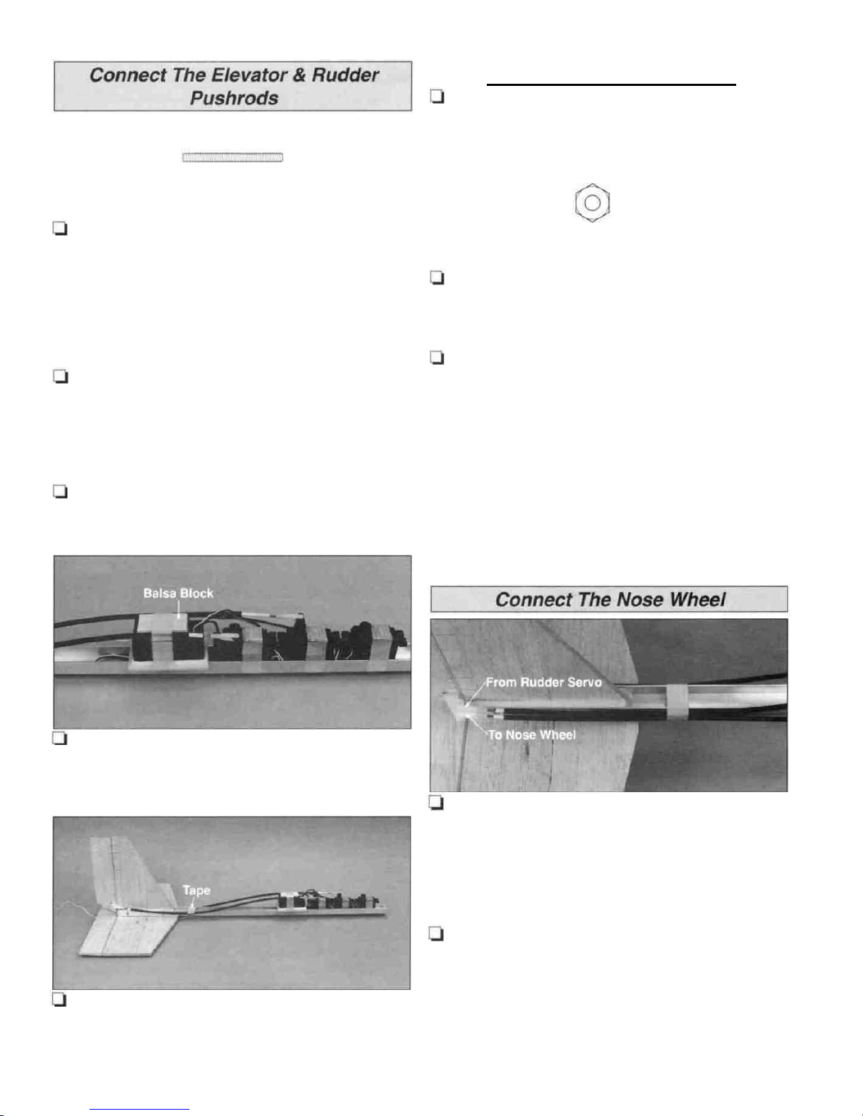
DuraPlane Aerobat 40 User manual

Aerobat40
AlmostReady-to-Fly
Assembly Instructions
Specifications:
Wingspan:
Wing Area:
Weight:
Fuselage Length:
44 in(120 mm)
420 sq
in
(27.1
sq
dm)
5.5
lb
(290
g)
38.75 in(984 mm)
Engine Required: High-performance
2-stroke.40 to .46 cu in(6.5-7.5cc) or
4-stroke.48cu in(7.86cc)
Radio Required: 4-Channel with
4servos
READ THROUGH THIS INSTRUCTION MANUAL BEFORE BEGINNING ASSEMBLY. ITCONTAINS
IMPORTANT INSTRUCTIONS AND WARNINGS CONCERNING THE ASSEMBLY AND OPERATION OF
THIS MODEL.
DuraPlane
P.O.
Box
788
Urbana,IL61801
(217)398-8970
PrintedinUSA DURA1130 3005059
ENTIRE CONTENTS © Copyright 1995

The Aerobat 40 isthe third generation of DuraCraft models
specificallydesignedforacrobaticflightBecausethe
Aerobat 40 isfullyaerobatic, itisrecommended that you do
notattempt to fly itasyour first model.
Althoughdesigned foradvanced flying, the Aerobat 40
maintainsthetraditionofsimpleconstructionand
outstanding durability that you have come to expect from
DuraCraft models
Ifthis isyour firstmodel, the bestway to learn tofly R/C is
to joina flyingclub The Academy of Model Aeronauticsis
thenationalorganizationthatchartersmodelclubs,
sanctions competitions and insures flyingfields throughout
theUnitedStatesWeurgeyoutojointheAMA
Membership will bring you flyinginsurance, a subscription
to Model Aviationmagazine and many other benefits The
AMA will gladly send you membership informationand lists
of AMA-charteredclubs inyour area where you can seek
the help of experienced modelers.
Academy of ModelAeronautics
5151 East Memorial Drive
Muncie, Indiana 47302-9252
(800)435-9262
Your hobbyshop isalso aninvaluable place for service,
partsand informationthatyou requireWe urge you to
patronize your local hobby dealer, he's there to help you
enjoy your hobby.
Finally,ifyou have any questions or comments aboutyour
DuraPlane, please write or callusat:
DuraCraft
PO
Box
788
Urbana, IL61801
(217)398-8970
Radio controlmodels are intended for adults or use under
the close supervisionof an adult Flying model airplanes
can bedangerous and can cause serious injury DuraCraft
assumes noresponsibility for accidents or injury caused by
this product.
This instructionmanual provides step-by-stepinstructions
forassembling the Aerobat 40 kit Assembly of the Aerobat
40 consists of eight major steps and must becompleted in
the following order:
BUILD THE TAILFEATHERS .....................Page 3
BUILD THE WING ....................Page 5
ASSEMBLE THE FUSELAGE ..................Page 6
RADIO INSTALLATION Page 8
COVER THE WING & TAIL SURFACES Page 10
FINAL ASSEMBLY ......................Page 11
BALANCE THE MODEL
....................
Page 12
FINAL HOOKUPS & CHECKS...................Page 12
FLYING........................................................Page14
To assemble the Aerobat 40, you need the following tools:
Warranty
DuraCraft guarantees this kitto befree from defects inboth
materialand workmanshipat the date of purchase This
warranty does not cover any component parts damaged by
use ormodification Innocase shall DuraCraft'sliability
exceedthe originalcostof the purchasedkit DuraCraft
reservestherighttochangeormodifythiswarranty
without notice.
Flatbladeand phillips screwdrivers
Small pliers (needle nose)
Hobby knife with #11blades
Electric drill
Drill bits 1/16", 7/64", 1/8", 5/32", #18 (or 11/64")
Hobby coveringiron w/Hot Sock - optional
(TOPR2175)
Sandpaper assortment andsandingblock
Ruler& felt-tippen
Masking tape

Trimoff the excess
screw threads
Inaddition to the parts included with the Aerobat 40 kit, you
need the following accessories (we have had good success
usingGreatPlanes-brand Adhesivesand Accessory
Items):
Four-channel radiow/4 servos
.40-.46 2-stroke engine w/muffler or.48
4-stroke engine.
Propellers (see engine instructions for
recommended size)
1roll Top Flite' EconoKote® modelcovering film
6-minute epoxy - (GPMR6045)
30-minute epoxy - (GPMR6047)
1
oz.thinCA- (GPMR6002)
1oz. medium CA - (GPMR6008)
Aliphatic resin (whiteglue) - optional (GPMR6160)
#6x1"engine mounting screws - 4 (GPMQ3134)
2-1/4" spinner
8oz. fuel tank - (GPMQ4103)
12" medium silicone fueltubing - (GPMQ4131)
Box of #64 rubber bands - (HCAQ2020)
5/32" wheel collars - 2 (GPMQ4306)
1/4" Foam rubber sheet - (HCAQ1000)
2-1/2"wheels- 3 (GPMQ4223)
Fiberglass reinforced "strapping" tape
1/2" Double-sided foam mounting tape (GPMQ4440)
1/16"x 5/16" wing seating foam tape (GPMQ4422)
Loctite®threadlock
Refer to the Parts List fora description of the parts and
hardware included with the Aerobat 40 kit.
2. Sand the Leading Edge (LE) of the shaped 1/4"
balsaRuddertoa "V"shapetoallowformovement.
Positiona nylonControlHornon theruddersothe
bottom edge of the horn is7-1/4"below the top of the
rudder. Use the control horn as a template to drill two 1/16"
holes forthe 2-56 x 1/2" screws.Push the screws through
the control horn. Then thread them into the Control Horn
Back Plate until itissnug.
fin as shown inthe photo above.
1.Glue the shaped 1/4" balsa FinFront to the FinRear
with medium CA.Use 150-grit sandpaper and a sanding
block tosand the Fin flatand evenbeforeproceeding.
Glue the 1/4" x 1/2" x 5-7/8" balsa FinBase Sides to both
sides of the Fin.Make sure that the bottom of the fin and
thebottomsof the finbase sides are flush.
4. Use a hobby knife with a #11blade to cut the hinge
slots.Tip: Carefullymove the blade back and forthto
enlarge the slot.
3.Mark the locations of the Hinges on the rudder and
3

use scissors to snip the corners off.Test fitthe hinges to
see ifthe slots are deep enough.
hinges. Donot glue the hingesinthefin and rudder
untilinstructed to doso.
5. Cut the hingesfrom the 2" x 9"CA HingeStrip, then
6. Temporarilyjointheruddertothefinwiththree
3.Sand the leading edgeofthe1/4"balsaElevator to a
"V" shape. Cut fourhinge slots inthe elevator and stabilizer
at thelocationsshownin thephoto.Withoutusing any
glue, temporarilyjointhe elevatorto the stabilizerwith
four hinges.
4.Draw a lineon the top of the elevator 6-7/8" from the
lefttip. Align the leftedge of a nylon control horn with the
line, then drill two 1/16" holes through the elevator- just
the same as you did on the rudder. Mount the control horn
tothe elevator with two 2-56 x 1/2"screws andthe backplate.
Rear withmedium CA.Tip: Sand the Stabilizer flat and
even before proceeding. Draw a centerline on the stab and
also on the 1/16" plywood StabilizerBottomPlate.
plate to the stabilizer.The end of the bottom plate should
beflush with the TE of the stabilizer. Seethephotoatstep 3.
1.Glue the shaped 1/4"balsaStab Front to the Stab
2. Align the center lines. Then glue the stabilizer bottom
1.Drill two 1/8" holes through bothsides of the rear of
the Aluminum Fuselage Channel at the locations shown
inthe photo (the rear isthe end withthe two pre-drilled
smaller holes inthe bottom that are closer together). Insert
the fin inthe fuselage channel so that the trailing edge is
aligned with the aft edge of the channel. Mark the location
of the holes inthe bottom and the sides of the fuselage
channelon thefin.Removethefinand drill1/8" holes
through only the marks on the sideof the fin.
4

2.Align the centerline you drew on the stabilizer bottom
plate with the holes inthe fuselage channel and mark their
location. Note: The TE of the stab should bealigned with
the end of the channel. Drill 1/8"holesthrough the slot at
themarks.
4-40x3/4"
Machine Screw
3.Use6-minute epoxy to glue two 4-40 x 3/4"machine
screwsinthe bottom rear holes of the fuselagechannel.
Afterthe epoxyhas cured, temporarily mount the stab to
the fuselagechannel with the 4-40 screws, #4 washers and
two 4-40 nuts. Note: The bottom of the stab isthe side
with the 1/16" plywood stabilizer bottom plate.
4-40x1" MachineScrew
1.Cut both 1/4" x 5/16" x 24" balsa Trailing Edges to a
length of 22" and both1/4"x 1"x 24" balsa Ailerons to a
length of 20".
2. Use aliphatic resin ("white glue" such as Great Planes
Pro ) or epoxy to glue the trailingedges to the wing. Use
masking tape to hold the trailing edges inposition until the
glue cures. Tip: Ifyou decide to use 6-minute epoxy,mix
one batch at a time.Don't tryto glue both trailing edges
with the same batch.
3.Sand the leading edge of the ailerons to a "V" shape
needed to clear the heads of the screws,then temporarily
mount the finto the fuselagechannel with two 4-40 x 1"
machine screwsand nuts.
4.Removematerialfromthebottomof the finas
to allow forcontrolmovement. Mark the locations of the
hinges on the aileron and the wing as shown inthe photo.
Then make the hinge slots justthe same as you did forthe
rudder and elevator. Temporarily attach the ailerons to the
wingwith the hinges.
Install
The Aileron
Servo
1.Cut the 1/8"x 1/4"x 2" plywood Servo Mount into
two 7/8" long strips. Then glue them to the servo railsinthe
middle of the wing with 6-minute epoxy.
5
Table of contents
Other DuraPlane Toy manuals
Popular Toy manuals by other brands

FUTABA
FUTABA GY470 instruction manual

LEGO
LEGO 41116 manual

Fisher-Price
Fisher-Price ColorMe Flowerz Bouquet Maker P9692 instruction sheet

Little Tikes
Little Tikes LITTLE HANDIWORKER 0920 Assembly instructions

Eduard
Eduard EF-2000 Two-seater exterior Assembly instructions

USA Trains
USA Trains EXTENDED VISION CABOOSE instructions