DuraPlane DuraStik 40 User manual

Assembly Instructions
Specifications:
Wingspan:
Wing Area:
Fuselage Length:
RadioRequired:
56in(1422mm)
594 sq in(37.9 sqdm)
49 in(1117.6mm)
4-Channel with 4 servos
Weight: 5.5to6 lb(2743g)
EngineRequired:
2-stroke .40to .46engine w/muffler, or
4-stroke .48to.52engine
READ THROUGH THIS INSTRUCTION MANUAL BEFORE STARTING CONSTRUCTION. ITCONTAINS
IMPORTANT INSTRUCTIONSAND WARNINGS CONCERNING THEASSEMBLY AND OPERATION OF
THIS MODEL.
DuraPlane guarantees this kit to befreefromdefects inboth material and workmanship atthe date of purchase.
This warrantydoesnot coverany componentpartsdamagedby use or modification.In no caseshall
DuraPlane's liability exceed the original cost of the purchased kit. DuraPlane reserves the right to change or
modify this warranty without notice.
DuraPlane P.O.Box 788Urbana,IL61803 (217)398-8970
Printed inUSA DURA1140
ENTIRECONTENTS© 1997

Thank you for purchasing the DuraPlane DuraStik 40 The
DuraStik 40 is the thirdgeneration of DuraPlane models
specificallydesignedforaerobaticflightThestick
configuration isreminiscent of the popular Great Planes stik""
series and isa perfect subject fora fastbuilding aerobatic,
fun flying DuraPlane model Because the DuraStik 40 isfully
aerobatic featuring a wing that has nodihedral (and does not
possess the self-righting characteristics found ina trainer), it
isrecommended that you donotattempt to fly the DuraStik
40asyour first model.
Ifthis isyour first model, the best way to learn to flyR/C is
to joina flyingclub The Academy of Model Aeronautics is
thenationalorganizationthatchartersmodelclubs,
sanctions competitions, and insures flyingfieldsacross the
United States We urge you to jointhe AMA Membership
willbringyouflyinginsurance,a subscriptiontoModel
Aviation Magazine, and many other benefits The AMA will
gladly send you membership information and lists of AMA
chartered clubs inyour area where you can seek the help
of experienced modelers.
Academy of ModelAeronautics
5151 East Memorial Drive
Muncie, Indiana 47302-9252
(800) 435-9262
FAX (765) 741-0057
Web Site:HTTP.//WWW.MODELAIRCRAFT.ORG
Your hobby shop isalso an invaluable place forservice,
partsand informationthatyourequireWe urgeyouto
patronize your local hobby dealer - hes thereto help you
enjoy your hobby.
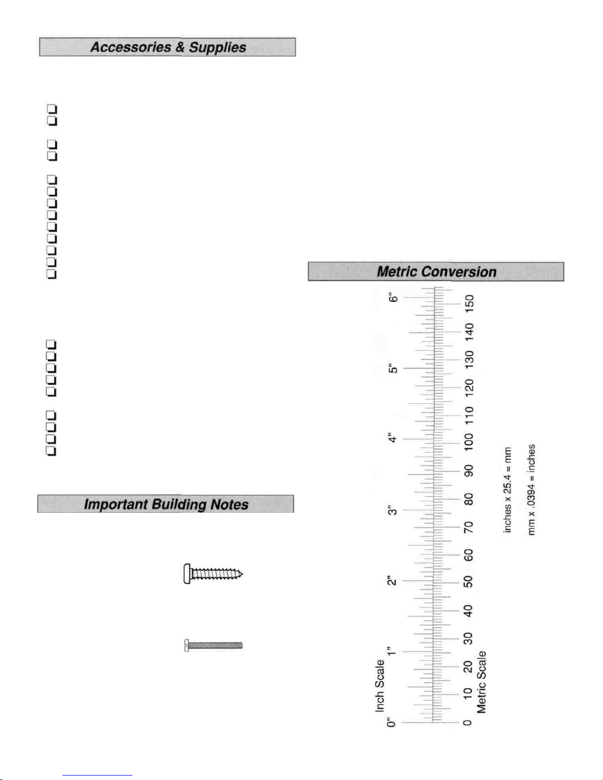
#11Blades(HCAR0311, 100qty.)
Razor Plane (MASR1510)
Standard and Phillips screwdrivers
Needle nose pliers
Electric drill
Drill Bits 1/16", 3/32", 7/64", 1/8",5/32",
#19 (or 11/64"), 3/16", 15/64" (or 1/4")
X-Acto Building Square (XACR7726)
Kyosho Lexan Curved Scissors (KYOR1010)
Masking Tape
Waxed paper
TopFliteSealing Iron (TOPR2100)
Top Flite "HotSock"(TOPR2175)
Easy-Touch"BarSanders"
Great PlanesC G Machine (GPMR2400)
*A flat,durable, easy to handle sanding toolis a necessity
forbuilding a wellfinished model Great Planes makes a
completerangeof Easy-TouchBar Sanders(patent
pending) and replaceable Easy-Touch Adhesive-Backed
Sandpaper While building the DuraStik, we used a 5-1/2"
BarSander and an11" BarSander equipped with 80-grit
and150-grit Adhesive-backed Sandpaper.
This instruction manualprovides step-by-step instructions for
assembling the DuraStik 40 kit Assembly of the DuraStik 40
consists of six majorsteps,completed inthe following order
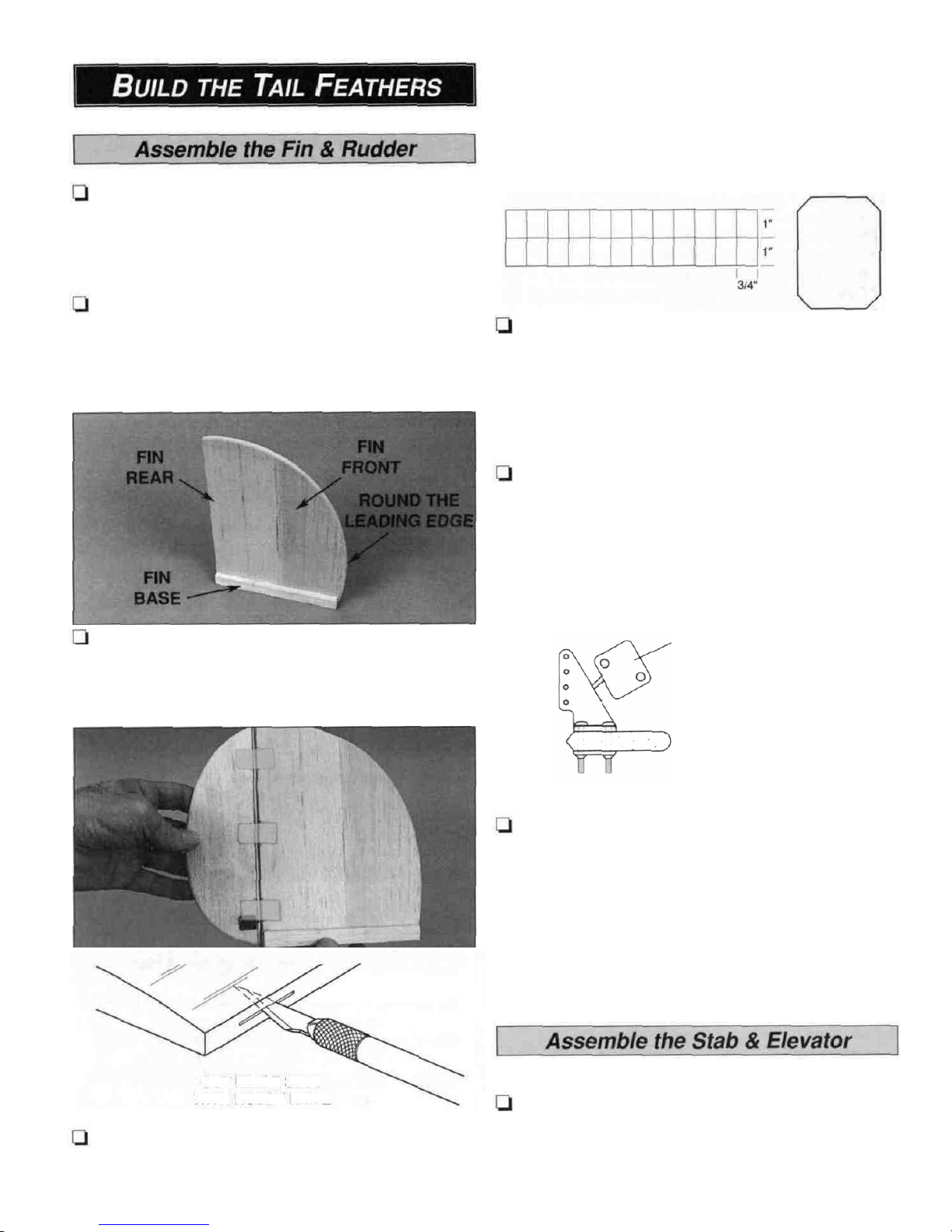
BUILDTHETAIL FEATHERS..................................4
ASSEMBLE THE FUSELAGE...................................6
RADIO INSTALLATION
............................................9
BUILD
THE
WING
...................................................12
COVER THE WING AND TAIL................................15
FINAL ASSEMBLY..................................................17
FLIGHT....................................................................19
Here's the complete listof Easy-Touch BarSanders and
Adhesive BackedSandpaper.
5-1/2" Bar Sander (GPMR6169)
11" BarSander (GPMR6170)
22" Bar Sander (GPMR6172)
33" BarSander (GPMR6174)
44"BarSander (GPMR6176)
Adhesive-backed 12' roll of:
80-grit (GPMR6180)
150-grit (GPMR6183)
180-grit (GPMR6184)
220-grit (GPMR6185)
Assortment pack of 5-1/2" strips (GPMR6189)
We use3M 320-grit wet-or-dry sandpaperfor finish sanding.
2

Fourchannel radio w/4 servos
40 to 46 2-stroke engine w/muffler,or 48 to 52
4-stroke engine
Propellers recommended byyour enginemanufacturer
1Roll EconoKote or Black Baron filmlow-heat
model covering (see Covering, page 16)
Fuel-proof spray paint (see Painting, page16)
(3) 2 1/2" wheels (GPMQ4223)
2-1/4" Spinner (GPMQ4517 - red)
8oz Fuel tank (GPMQ4103)
Medium siliconefueltubing (GPMQ4131)
#64 Rubber bands (HCAQ2030)
1/4" R/C foamrubber sheet (HCAQ1000)
3/4" Wide fiberreinforcedstrapping tape
1/16" Wing seating foam tape (GPMQ4422)
These are additional items you will need to complete your
DuraStikthatarenot included with your kit. Suggested
order numbers are inparentheses
When a specific type of adhesive works best for that step,
we willtellyouwhattypeofglueto use CA dissolves
foam so donotuseiton any part of the wing where it
will contact the foam. Whenever justepoxy isspecified
you may use either 30-minute epoxyor 6-minute epoxy
When 30-minute epoxy isspecified itisrecommended
that you use only 30-minute epoxy because you will need
the working time and/or the additional strength
When you get to each step,read that step completely
through to the endbefore you begin Frequently there is
important information or a note atthe end of the step that you
need to know before you start Photos and sketches are
placedaheadof the step they refer to You can study photos
inthe following steps to get another view of the same parts.
Refer to the Parts Listfora description of the partsand
hardware includedwith the DuraStik 40 kit
Here'sa checklist of supplies you should have on hand
while you'rebuilding We always use Great Planes Pro"
CA and Epoxy.
1oz Medium CA+ (GPMR6008)
1oz Thin CA (GPMR6002)
CA Accelerator (GPMR6035)
CA Applicator Tips (HCAR3780)
30-minute (GPMR6047) or 6-minute epoxy
(GPMR6045)
Pro Wood Glue (GPMR6161)
Pro Threadlocker (GPMR6060)
Lightweight Hobby Filler (White,HCAR3400)
Denatured or IsopropyI Alcohol (to clean upexcess
epoxy)
There are two types of screws used inthis kit:
Sheet metal screws
are designated bya
number and a length.
Forexample #4 x 3/4"
Machine screws are
designated bya
number, threads per
inchanda length. Forexample 4-40 x 3/4"
When you see the term test fit inthe instructions itmeans
thatyoushouldfirstpositiontheparton theassembly
without usingany glueand then slightly modify or custom
fit the partasnecessary for the best fit.
3

bladeto cut the hingeslots inthe centerof the fin TE and
the center of the rudderLEatthe locations you marked.
1.Test fit the shaped1/4"balsa fin front to the shaped
1/4" balsafinrearas shownin the followingphoto.
Ifnecessary, true the joining edges with a barsander and
150-gritsandpaperso thereis no gap betweenthe
two pieces.
2. Glue the fin frontto the finrear with medium CA.
From now on we will callthis assembly the fin. Use your
barsander and 150-grit sandpaper to sand the sides of the
fin flat and even andround the leadingedge.Sandthe fin
smooth with 320-grit sandpaper.
5.Cut three hinges fromthe 2"x 9"CA Hinge Strip
andsnip the corners offas shown inthe sketch. Test fitthe
rudderto the finwiththehinges.Do not glue inthe
hinges until weinstruct you to do so. If necessary,
adjust the hingeslots so the rudderandfin align.
6.While the fin andrudderare stilltemporarily joined
with the hinges, round the trailing edge of the rudder so it
matches the fin.Remove the rudder fromthe fin.Use a
razor plane or sandpaper to shape the leading edge of the
ruddertoa"V".
fin bases to both sidesof thefin. Make surethat the
bottom of the fin andthebottom of the fin basesalign.
Usethis photo for the next foursteps
where shown inthe photo. Usea hobby knife with a #11
3.Usemedium CA to glue the 1/4"x 1/2" x 5-5/8" balsa
CUT HINGE SLOT
WITH HOBBY KNIFE
AND #11 BLADE
4. Mark the locations of the hinges on the rudder and fin
Horn plate
Positionthe horn so
the holes align with
the leading edge.
7.Cut the horn plate off a large nylon control horn.
Position the control horn on the right side of the rudder so
the baseis9/16" fromthe bottom of the rudder, and the
four holes (forthe clevis) align with the LE. Use a ballpoint
pen to mark the location of the two holes inthe base of the
control horn on the rudder and drill two 1/16"holes through
the rudder at themarks.Mount the controlhorn tothe
rudderwith two 2-56 x 1/2" screws and the horn plate.
1.Testfitthe shaped 1/4" balsa stab fronttothe
shaped 1/4" balsa stab rear. Ifnecessary, true the joining
edges with 150-grit sandpaper anda barsander so there is
nogap between the two oieces.
4

2. Gluethe stab front to the stab rear with mediumCA.
From now on wewillcallthisassemblythestab. Use
150-gritsandpaperand a sandingblock toround the
leading edge of the stab and sand the top andbottom flat
andeven. Sandthe stab smooth with 320-grit sandpaper.
7.Mounta control horn to the top of the elevator with two
2-56 x 1/2" screws andthe horn plate.Position the edgeof
the horn base 8-7/16" from the leftedge of the elevator.
3.Draw a vertical centerline onthe center of the stab and
the 1/16" x 1-1/8" x 6"plywood stabilizerbottomplate.
4. Use medium CA to glue the stab bottom plate to the
stab withthecenterlinesaligned. Afterthe CA hardens,
shape the front of the stab bottom plate so itmatches the
front of the stab.
a
1.Inspect the holes inthe aluminum fuselage channel
andremove anyburrsyou find with a metalfile.
5.Mark the locations of the hinges on the stab and 1/4"
shaped balsa elevator as shown inthe photo at step 7.
Cut the hinge slots inthe stab and elevator the same way
you did the finand rudder. Cut fourmore hinges fromthe
CA hinge strip and testfitthe elevator to the stab with the
hinges.Ifnecessary, adjust hingeslots that don't align.
6.While the elevator and stab are still temporarily joined
with the hinges, round the ends and TE of the elevator to
match thestab.Removetheelevatorand use a razor
plane or sandpapertoshape theleading edge ofthe
elevator to a "V".
2. Insert the fininthe aluminum fuselage channel so the
trailing edge aligns with the aft edge of the channel. Mark
the locationof the holes inthebottom and sides of the
fuselage channel onto the fin.Remove the finand drill 1/8"
holes through only the marks on the side of the fin.
5

the 1/16" ply bottom plate). Align the centerline you drew
on the stab bottom plate with the holes inthe bottom of the
fusechannel and align the trailingedge of the stab withthe
aftedge ofthefusechannel.Make surethatthestab
trailing edge is perpendicular to the fusechannel. Mark the
holes inthe fusechannel onto the stab bottom plate. Drill
1/8" holes atthe marks on the stab.
Mount the Engine & Install
the Fuel Tank
3. Place the fusechannel on the bottom of the stab (on
Note thegraindirection
1.Glue the three die-cut 1/8" plywood firewall formers
Btogetherwithepoxyso the edges accurately align and
the grain directionof the middle formeris90 degrees to the
grain direction of the outer two formers.Wipe away excess
epoxy before itcures.
4. Useepoxy to glue two 4-40 x 5/8" screws inthe holes
inthe bottom of the rear of the fuselage channel. Afterthe
epoxyhas cured,temporarilymountthestabtothe
fuselagechannel and secure it withtwo4-40nuts and
#4 washers.
Note:The bottom of the stab isthe sidewith the 1/16"
plywood stabilizer bottom plate.
2. Test fitthe sandwiched formers inthe front of the
extrudedPVC fuselage. Ifnecessary, sand the edges of
the formersso they fit.
3. Gluethe die-cut 1/8"plywood front firewall former
A,centered,tothethreeformers.Alternatethegrain
direction again. From now on this assembly will bereferred
to asthe firewall.
5. Removematerialfromthebottomof thefinas
needed to accommodate the heads of the screwsinthe
fusechannel that hold the stab on. Temporarily mount the
fin to the fuselage channel with two 4-40 x 1"screws and
4-40 nuts. 4. Fitthe firewall to the frontof the fuselage. Sand the
edges flush with the fuselage sides.
6

5. Cut the spreader bar and other flashing fromthe right
and left Great Planes 40-70 engine mount halves.
6.Drillfour 5/32" holes through the firewallat the four
punch marks infirewallformerA.Use a hammer to lightly
tap four6-32 blind nuts into theholes inthe back of the
firewall.Permanently secure the blindnuts to the firewall
with thin CA.
7.Fasten the engine mount to the firewallwith four
6-32 x 1-1/2" bolts and #6 lock washers and flatwashers.
Donot fully tighten the bolts so you can adjust the engine
mount to fit your engine.
For a sportier appearance, you may side mount your
engine. Just rotate your engine mount (or the firewall) 90
degrees and drill the holes forthe fuellines and throttle
pushrod accordingly. This also locates the muffler below
thefuselagewhich greatlyreduces exhaustresidue
deposited on your model!
secure. Position your engine onthe mount andmark the
location of the mounting holes.
Hint:Sharpen the end of a 1/16" wire rod to a point. Heat
the rod with a lighter anduseitto mark the mounting holes
on the engine mount.
9.Drill four3/32" holes at the marks you made for
mounting your engine with #4 x 3/4" sheet metal screw and
#4 washersincluded withthiskit.Ifyoupreferto mount
your engine with4-40 screws,drill the holes witha #43 (or
3/32") drill. Tap the holes with a 4-40 tap.Use4-40 x 3/4"
screws (not included).
Note: #4 or 4-40 screwsare intended forsportengines
such as the O.S. LA or FP'series. Ifyou are using a more
powerfulengine,use #6 or6-32screwstomountyour
engine. Drill the holes with a 7/64" drill for#6 screws or a
#36 or 7/64"drillfor 6-32 screws.
10.Take the engine mount offthe firewall. Drill a 3/16"
hole throughthe firewallthataligns withthecarburetor
arm. Make sure you don't drill the hole where the engine
mount willbe. Ifthe engine mount will beinthe way,drill
the hole closetotheenginemount to givethethrottle
pushrod the straightest run possible to the carburetor arm.
Drill 15/64" (or 1/4") holes through the firewallforthe fuel
lines. Make sure the holes willnot interferewith the engine
mount.Whenyou'redone,yourfirewallshouldlook
something like the one inthe photo.
8.Slide the engine mount halves inor out to fityour
engine. Tighten the 6-32 bolts so the engine mount is
11. Mark the locations onthe sides, top, andbottom of
the frontof the fuselage forthe firewallmounting holes,
evenly spaced, 1/4"behindthe front edge.Fitthe firewall
7

into the fuselage,making sure the hole forthe throttle
pushrod isinthe correctorientation Tightly tape the firewall
inplace with masking tape Confirm that the locations of the
holes will not interfere with the throttle pushrod Ifthey do,
adjust the locations of those holes Drill holes through the
fuselage and intothe firewall with a 3/32" drill.
12Removethe firewallAssembleyourfueltank
Connect about 8"of fuel line onto the pickup and pressure
fittings on your fueltank Place an approximately 4" x 4"
piece of 1/4" thick R/C foamrubber inthe fuselageas
shown inthe photo so the frontedge isabout 3/4" aft of the
frontedge of the fuse Insert the fueltank into the fuse with
the R/C foam rubber Slide the 12"long,3/16" grey outer
pushrod guidetube into the fuse between the R/C foam
and the fuse so the end will fitinthe hole you drilled in
the firewall
13Fitthe firewallto the fuselage,simultaneously
2Enlarge the middle hole inthepre bent aluminum
landing gear with a 3/16"dnll Place the landing gear on
the bottom ofthefuseand insertan 8 32 x 1/2" socket
head cap screw(fromnow on referredto as cap screw)
intothe middle hole of the landing gear and into the fuse
Drilla 7/64" hole throughthefuselagewheretheouter
holes inthe landing gear align with the line on the bottom
of the fuselage The shaded areas show the location of the
landinggear plates that will beinstalled instep 3.
3Round one corner on the bottom of both landinggear
plates so they fitthe curve inside the fuselage The bottom
of the landinggear plates isthe side with the line you drew.
Place oneof the landinggear plates inside the fuselage so
the lineyou marked isvisible through one of the holes you
drilled inthe bottom of the fuseMark the location of the hole
on the landinggear plate Drill a 7/64" hole through the plate
atthe mark you made Mark and drill the other landinggear
plateinthe other side of the fuse the same way
routing the fuel lines andthe throttle guide tube through the
holes you drilled Temporarily fasten the firewall to the fuse
with eight #4 x 3/8" screws
4Enlarge theoutertwolanding gear holes inthe
fuselageonly witha 5/32"drillbit Use two#6 x 1/2"
screws to mount the landing gear to the fuselage with the
landing gear plates inside You may glue the landing gear
plates to the fuselage with epoxy,butthis isnot necessary.
Mount the Landing Gear
5/32" Wheel Collar
Nylon Steering arm
with 5/32" Wheel
Collar and 6-32 x
1/4"Screw
1Place the fuselage flaton its side so the firewallisoff 5Remove the enginefrom the enginemountSecure the
the end of your workbench Use a 90 triangle or a builder's
square to mark a line across the fronthole in the bottom of
the fuselage Draw a line across the middle of each 1/4"x
5/8" x 3-1/2" plywood landinggearplate.
wire nose gear to the engine mount with two 5/32'wheel
collars andthe nylon steering arm with another wheel collar
as shown inthe sketch Usetwo 6 32 set screws inthe wheel
collars anda 6-32x 1/4" screw inthe nylonsteering arm
8

6.Drill the hub of two 2-1/2" mainwheels with a #19 (or
11/64") drill. Secure each wheel to the landing gear with an
8-32 x 1-1/4"cap screw and two8-32 nuts as shown inthe
photo. Use thread locking compound on the nuts. Mount
the frontwheeltothenose gearwithtwo5/32"wheel
collars. For a finished appearance, cut the excesswire off
the landing gear that protrudesbeyond the wheel collar
(you should dothis on allyour models').
7.Place the fuselageon yourworkbench.Adjustthe
wheel collarson the nose gear so the fuselageislevel.
Secure the 6-32 screws inthewheel collars with a drop of
thread lockorCA.
Optional: Forextrasecurity, fileflat spots on the nose
gearwhere the set screws lock on.
1.Insert three servos into the fuselage channel inthe
orientation shown inthephoto. The front servo(throttle)
should beabout 1/2" fromthe frontof the fuse channel. The
middleservo (rudder) should beas far forward as possible,
yet not concealing the hole forthe frontscrew that holds the
fuse channel to the fuse.The aft servo (elevator) should be
asclose as possible to the rudder servo without touching it.
Securely wrap two layers of 3/4" wide fiber reinforced tape
around the servos and the channel. Install a servo arm on
each servo asshown inthe photo.
2.Temporarily connect the servos to the receiver and
the battery pack. Turn on your radio and center the servo
arms on the servos.Turn offthe transmitterand receiver
anddisconnect the receiver andbattery.
CUTOFF
UNUSED
ARMS
3.Center andglue the 1/2"x 3/4" x 2"balsa blockto the
die-cut1/8"plywood receiver plate.
9

THREADED STUD
1.Thread a nylon clevis onto a 1"threaded stud about
20 fullturns. Thread the other end of the stud about 1/2"
into a 36" innerpushrod tube. Connect the clevis to the
controlhorn on theelevator and slip a 36" greyouter
pushrod guidetube over the inner pushrod tube.6.Trim the 3/16" x 1" x 1-1/4" balsa pushrod spacer
2.Connect another 36" inner pushrod tube and another
36" outer pushrod guide tube to the second fromthe inner
hole on the rudder horn the same as the elevator.
3.Thread one more nylon clevis onto a 1"threaded stud
block so that when you place iton top of your receiver, the
pushrods willalign withtheelevator and rudder servowhen
you run them alongside the block on top of the receiver.
Wraptwoturnsof filamentreinforcedtapearound the
assembly and the fuse channel to hold everything inplace.
and thread the stud into one end of the 48" inner pushrod
tube. Connect the clevis to the second fromthe outer hole
of the rudder horn. Slide a 36" outer pushrod guidetube
over the 48" pushrod tube.
4. Securely tape the outer pushrod tubes to the fuselage
channel about 1"ahead of the stab withfiberreinforced
tape. Make sure the aft end of the tubes donot interfere
withthe cleviseswhen you move the rudder and elevator
to fulldeflection. The short rudder pushrod tube should be
above the long nose wheel steering tube on the rightside
of the fuse channel.
7.Disconnect the clevises fromthe rudder and elevator
horns and slide the pushrods out of the guide tubes. Cut
the rudder and elevator guide tubes about 1-3/4" short of
the elevator andrudder servos. Reinsert the pushrods in
the guide tubes. Cut the pushrods to the correct length and
connectthem to theelevatorand rudder servowithtwo
more 1"threaded studs and nylon clevises.
At this point yourreceivershould besecurely(yetsoftly)
mounted to the fuse channel, your servos should besecurely
mountedto the fuse channel and plugged into your receiver,
your elevator andrudder pushrods should beconnected,and
your fuel tankandfuel linesshouldbeinstalled.
5.Place your receiver and thereceiver plateon the fuse
channelwith1/4"R/Cfoamrubberunder thereceiver.
Connect your on/offswitch, throttle,rudder and elevator
servo cords and anaileron extension cord to your receiver. 8-32 x 1/2" cap screws, #8 washers and 8-32 nuts anda
drop of thread lock.Mountyour engineto the engine mount.
10

Refer to this photo for the next two steps.
2.Secure the nose wheel steering outer pushrod guide
tube tothebottomof the fusewithtwonylonpushrod
clampsand two#6 x 1/2"screws.Positionthefront
pushrod clamp so the pushrod aligns with the nose wheel
steering arm. Position the aft pushrod clamp so the guide
tube makes a smooth transitionfromthe right side of the
fuse to the left side of the fuse.Drill 7/64" holes inthe fuse
forthe #6 screws. Make sureyou donotdrilla holeinto
the fuel tank.
RETAINER
6. Bend the aftend of the rod so italigns with the
3.Cutthe nose steering pushrod to the correct length
and connect itto the nose wheelsteering arm with a 1"
threaded stud and a nylon clevis.
throttleservoarm.Connectthethrottlepushrodto the
throttleservoarm witha brass body screw-lock pushrod
connectorand a 4-40x 1/8"cap screw.Securethe
screw-lock pushrod connector to the servo arm with a
nylon retainer.
4. Slide the throttle pushrod guide tube toward the front
of the fuselage so the aft end isapproximately 1-1/4" from
the throttleservoarm. Cut the frontof the throttleguide
tube1/2"ahead of the firewall.Roughen the frontof the
guide tube with coarse sandpaper and use medium CA to
glueitinthe firewall. Donot get CA inside the tube.
7.Mount your muffler to your engine. Cut your fuel lines
to the correctlength and connect them to the carburetor
andthe pressure fitting onyour muffler.
8. Mount your on/off switch to the fuselage.You may
simply holditinplace with foam mounting tape or cut holes
inthe fuse and mount itfromthe inside withthe mounting
screws and face plate included with the switch.
hardwood wing dowels and coat them with fuelproof paint
or a thin layer of epoxy. Insert the dowels inthe fuse. Itis
not necessary to glue them inthe fuse.
9. Slightlyround theends ofboth 1/4" x 4-9/16"
5.Makethe throttle pushrod froma 2-56 x 36" wire rod
that's threaded on one-endand a nylon clevis.Insert the
pushrod inthe throttle guidetube. Bendthe front of the wire
asnecessaryso you canconnect the clevisto thecarburetor.
11

1.Mark centerlines on the 1/8" die-cut plywoodfront
and aft wing joiners. Glue the joiners together with epoxy
so centerlines align. Ifthe joinersare slightly warped, glue
them together so the warps cancel out. Lay the joinerson a
flat surface andplace a weight on top of them to holdthem
flat untilthe epoxy cures.
Makea dry run ofthe following three steps so you can
gather allthe items you'llneed and to makesure you
understand how to join the wing halves.
Note: We used aliphatic resin (wood worker's glue such as
Great Planes Pro wood glue) to glue the wing together.
You may also use 45-or 30-minute epoxy.
3. Laya sheet of waxedpaper over yourflatbuilding
table that isthe same length as your wing (approximately
54"). Working quickly, apply glue to the grooves that hold
the main spars inthe bottom of both wing halves. Apply
glue to the bottom spars. Insert the spars intothe notches.
Remove excessglue with a paper towel. Hold the bottom
spars inplace with masking tape so they won'tfallout of
thewingwhenyouturnit upsidedown.Immediately
proceed to the next step.
2. Test fitthe wing joinerinone of the wing halves.
Place a 3/16" x 1/2" x 30" basswood top and bottom spar
inthe spar notches of the wing. Ifnecessary, sand the top
andbottom of the wing joinerto allow the spars to fullyseat
intothe spar notches so the spars willbeflush with the top
andbottom surface of the wing.
4. Apply a film of glueto the end of both wing halves.
Turn the wing halves over and place them on the waxed
paperover your workbench. Push the wing halves together.
12

Shape the TE to
match the wing.
5. Apply glue to the top spar notches andthe notches
where the wing joiner fits.Apply glue to the wing joiner.
Insertthe wing joiner into the wing.
6. Apply glue to the top spars and insert them into the
notches inthe top of the wing the same way you did the
bottom spars. Wipe away any excess glue. Tightly tape the
winghalvestogetherwithmaskingtapeand hold the
center section inalignment with T-pins. Lay weights on top
of the wing along the top spars. Do not disturb the wing
untilthe glue isdry.
2.After the glue dries, use a razor saw to cut the spars
and TE'S so they are even with the tips of the wing. Use a
hobby knifeor a razor plane to shave the balsa TE'S so
they match the shape of the wing. Finish with a bar sander
and80-grit sandpaper. When you sand, use the foam wing
only to guide your bar sander butapply pressure only to
the spar. This way, you will sandonly thewood andnot
the foam wing.
3.Ifnecessary, sand the top andbottom spars so they
blendto the wing.
1.Glueboth 1/2"x 1/2" x 30" balsa trailing edges to
the trailing edge of the wing with aliphaticresin or epoxy.
4. Use aliphatic resin or epoxy to glue the die-cut 1/8"
plywood wing tip ribsto both ends of the wing. Usemasking
tapetoholdthewing tipribsinplaceuntilthegluedries.
13

5Mark the locations of the hinges on the aileron and
the trailing edge of the wing as shown inthe sketch Cut
the hinge slots and temporarily join the ailerons to the wing
with the hinges to make sure the hingeslots alignMake
adjustments if required
6Removetheaileronsfromthewingandusea
1/8"PLYWOOD
SERVO RAILS
1Temporarilyplace the die-cut 1/8" plywoodservo
rails inthe top of the wing Position your aileron servo in
thewingontopoftherailstomakesureitfitsIf
necessary,make adjustments to the servo cavity inthe
wing so your servo will fit
2Glue the servo railsinthe wing with epoxy After the
epoxycures, mount yourservo to the rails with the screws
included with vour servo
3UseKyosho Lexan Scissors or a hobby knife with a
sharp #11 blade to trim the plastic wing shield along the
molded-in outlines The outlines are most easily seen from
the undersideof the wingshield True the edges of the
wingshieldwitha bar sanderand 150 gritsandpaper
razorplane, a hobby knife,or a bar sander and 80 grit
sandpaper to shape the leading edge of both ailerons to a
"V" to allow for control movement Temporarily reattach the
aileronsto the wing with the hinges.
7Sand the wing tip ribs so they are even with the
wing Glue one of the die-cut 1/8" plywoodwing tips and
the wing tip brace to the left wing tip Becareful notto use
too much CA because itwilldissolve the foam.
8Glue a piece of leftover 1/2"x 1/2"balsato the
wing tip rib and the wing tip Shape the block to blendthe
wing, wing tipandwing tipribtogether.
4.Placethe wing shield onthe wing butdo notglueit
untiltold to do so. Use a pencil or a ball point pen to
lightly tracethe sides ofthewing shield onto the wing
This will show you where not to applycovering so you can
glue the wing shield directly to the wing
5Make a two-armed servo arm for the aileronservo.
Installthe servo arm on your aileron servo.
When youre done, your wing tipshould looklikethe
oneinthe photo 6Screw a nylon clevis about 20 turns onto each 12"
wire pushrod Connect a nylon control horn to each clevis
inthe second holefrom the bottom
9.Finishthe rightwing tipthesame way.
14

7Mount both control horns to the ailerons withtwo2 56 3Bevel the TE of the wing saddlewith a barsander
x1/2" screws and the mounting plate you cut fromthe
control hornThe edge of the horns should be1/4" fromthe
edge of the ailerons andthe control rods shouldalignwith
the servo arm
2-56 ( 074") servo Horn
Pushrod Wire
8Cut the pushrods to thecorrectlength and make a 90
degree bend inthe end Connect the pushrodsto the servo
arm with nylon Faslinks
and 150-gritsandpaperso it willnot interferewiththe
rubber bandsthat hold the wing to the fuse.
4Temporarily mount the wing to the fuselage with two
1.Apply Hobbico" HobbyLite™ filler to any dents or
#64 rubber bands and the wingshield Trimthemolded
front deck along the outlines (seen best fromthe inside)
andsand the edges so they are straightand trueTest fit
the frontdeck to thefuselageand thewing Trim where
necessary fora good fitDo not mountthe front deck to the
fuselage until instructed to do so.
molding imperfections inthe foam wing Afterthe fillerhas
dried,use a sanding blockand 220-gritsandpaperto
carefully sand the filler,the seam on the leading edge and
any other molding irregularitiesForthe best appearance, it
isrecommended that finalsanding bedone with 320-grit
sandpaper butwithout a sanding block
2Test fit the foam wing saddle on the bottom of the
wing Cut a hole inthe wing saddle to allow the aileron
servo cord to pass Use aliphatic resin or epoxy to glue the
saddle to the bottom of the wing, making sure itis centered
andaligned Place a weight on top of the wing to hold itto
the saddle until the glue dries
We presume that the DuraStikwill bebuiltbyexperienced
modelersbut due to itssimple,rapid construction,the
DuraStik may appeal to beginner modelers as well For new
modelers, or those unfamiliar with finishing techniques, we
have provided some basic information about the covering
materials available andthe sequence recommended
The foamwing and the balsa surfaces,includingthe
aileronsandtailfeathers,mustbe coveredwitha
protective,fuelprooffinishAmongthemanymodel
airplane covering materials available, Top Flite EconoKote
film or Black Baron filmisrecommended Both coverings
are applied with a hobby heat seal iron The temperature
required to activate the adhesive on some coverings istoo
high to beused overa foamwing Besure to check that
thecoveringyouhavechosenis fora low-temperature
application A low-temperaturecoveringlike EconoKote
film or Black Baron film must beusedon the wing.
15

One six footroll will beenough to cover the DuraStik but, if
you wish to add trimcolors or other designs, you will have
to purchase more than one roll
Covente alsooffers graphics, numbers, stars andlettering
the tail surfaces and remove the control horns and hinges
Remove the stabilizer and finfromthe fuselage channel If
you haven t already done so, final-sand allthe tail surfaces
with 320-grit sandpaper Tip: Ifyou don't mind a little extra
work andwould like to have a better looking model with a
more finished appearance, taper the ailerons, rudderand
elevatorby sanding thetrailingedges to a thicknessof
approximately 3/32" This isoptional and does not effect
the flight performance of your DuraStik.
1Disconnect the elevator and rudder pushrods from
2Disconnect the aileron pushrodsand removethe
control horns fromthe ailerons Detach the ailerons from
the wing andremove the hinges
3Make sure youhave finalsanded thewing, tail
surfaces and control surfaces.
4Before covering,remove as much balsa and foam
dust as possible left fromsanding This can bedone with
compressed air, a shop-vac with a brush, or a tack cloth
Now the DuraStik wing and tail feathers are ready to cover.
Ifyou planto paint any parts of your DuraStik such asthe
fuselage, landing gear frontdeck or the wing saddle, now
would bea good time to do itUse your favoritefuelproof
modelairplanespraypaintWe recommendTop Flite
LustreKote" or Black Baron spray paint.
Follow theinstructionsincluded withthe coveringyou
have selected.
Coverthewinginthe following order:
1.Bottom of the center section
2.Bottom right, then left side
3Top right, then left side
4Ailerons*
*Somemodelerscovertheends oftheailerons
separately If youuse this method cover the ends firstYou
can cover the top and bottom of the ailerons separately or
cover them inone piece, wrapping the covering allthe way
aroundTrytomake all seamsin thecoveringface
16

rearward or downward Overlap the linesyou drew on the
top of the wing forthe wing shield by1/4" Leave the rest of
the foam exposed fora good glue bond to the wing shield.
Cover the tail inthe following order:
1.Stabbottom, then top
2.Elevator
3.Finright, then left side
4.Rudder right, then left side
2Insert the hinges and jointhe elevator to the stab
Make sure there isa verysmall gap between the TE and
the LE of the controlsurfaceThis willkeep youfrom
inadvertently gluing the controls together Ifthe hinges do
not stay centered, insert a pinthrough the middle of the
hingebefore you jointhe surfaces Pullthe pinout after the
surfaces are connected.
ASSEMBLE THEN APPLY 6 DROPS
OFTHIN CA TO CENTER
OFHINGE,ON BOTHSIDES
centerof the hinge,on the top andbottom of the stab
4.Hingethe rudder andailerons the same way.
3.Glue the hinges by applying 6 drops of thin CA to the
1Start with the stab Slit the covering over the hinge
slots Drill a 7/64" hole 1/2" deep inthe center of the slots
that were cut previously This will enable the CA to "wick" into
thehinge.Remove the covering from over thehingeslots.
1Add stripsof1/4" x 1/16"thickwingseating foam
tape to the wing saddle area on the fuselage This will keep
the wing from shifting during flight.
17

not have a C G Machine, lift the model with your fingers at
the C G point (mark the C G on the bottom of the wing
with a felt tip penor a piece of tape so you know whereto
lift)Position the battery pack on the fuseuntil the model is
levelThisis thepositionwhereyoushouldmount the
battery pack inside the fuselageTry to position the battery
pack so no ballast will berequired to correct the C G The
C.G.mustbedetermined with the fuel tank empty.
2Place the wing shield on the wing and set the wing on
the fuselage Apply a filmof 30 minute epoxyto the wing
and the underside of the wing shield Place the wing shield
onthewingClamp thewingshieldtothewingby
mounting the wing on the fuselage with #64 rubber bands
Wipeawayexcessepoxybeforeitcureswitha cloth
dampened with rubbing alcohol.
Note:Your wing willbecovered atthis point.
3Mount the frontdeck to the fuselage with double
1Mountthe battery packThere are several ways to do
this Wrap the battery pack in1/4" thick foam and place it
inside the fuselage so itwill not shiftduring flightor a rough
landing Or, mount the battery pack to the inside of the
fuselagewithfoam mounting tape Onour prototype, we
mounted a 500 mAh flatbattery pack directly to the inside
of the fuselage next to the frontservo Inthislocation, no
additionalweight was required to achieve the correct C G.
sided adhesive tape.
4Mount the stab andrudder to the fuselage channel as 2Recheck the C G.Add stick-on lead weights to the
nose or tailifrequired to arrive atthe correct C.G.
CUT
CUT
/ou did during constructionUse threadlock or CA on all
the nuts Install the control horns on the rudder, elevator
and ailerons andconnect the pushrods.
5. Mount a 2-1/4" spinner (optional) and a propeller
within the range recommended bythe engine manufacturer
to the engine
This procedure (checking the center of gravity) must
not beomitted. A model that isimproperly balanced
will beunstable and possibly unflyable.
3Route the receiver antenna You can simply secure it
to the top of the finwith a piece of tape or make a strain
relief and antenna hook out of a servo arm as shown inthe
sketch Connect the rubber bandto a pininserted into the
top
of
the fin.
3-3/8"
tubing)to allthe clevises onthe model.
4.Add a silicone Clevis Retainer (cut from excess fuel
Mount the wing to the fuselagewith a couple of #64 5Check to make sure allthe servo mounting screws
rubber bands Withyourbatterypack handy, place the
model on your Top Flite C G Machine at the C G location
(3-3/8" backfrom LE)oneach side of the wing Ifyou do
and servoarm screwsthat hold theservoarmstothe
servosare installed and secureMake sureall wheel
collars are secure andhave threadlocker ifnecessary
18

We recommend the following control surface throws.
The throwsaremeasuredat thetrailingedge of the
ailerons, elevator, andrudder:
2.Balance your propellers. Vibration from anunbalanced
propeller can cause poor engine performance and damage
your inflight radio system. Purchase a Top Flite Power Point
Magnetic balancer (TOPQ5700) or a Great Planes Fingertip
PropBalancer(GPMQ5000)toaccuratelybalance
yourpropellers.
3.Make sure the fuel linesareproperlyconnected.An
in-line fuelfilterisrecommended.
4.Makesurethetransmitter andreceiver batteriesare
fully charged.
5.Performa range check of your radio system as
described by the radio manufacturer.
6. When it's time to mount your wing to the fuselage
at theflyingfield,use eight toten#64rubberbands.
Criss-cross the last two.
HighRate LowRate
1/4"UpandDown
3/8" UpandDown
Elevator
Ailerons 5/16"UpandDown3/16"UpandDown
Rudder1"Left andRight 3/4" Left and Right
Before You Go to the Flying Field
4-CHANNEL
RADIO SETUP
(STANDARD MODE 2)
ELEVATOR MOVES UP
RIGHT AILERON MOVES UP
LEFTAILERON MOVES DOWN
RUDDER MOVES RIGHT
NOSEWHEEL TURNS RIGHT
CARBURETOR WIDE OPEN
1.Confirm thedirectionof thecontrols.
The DuraPlane DuraStik 40 isintended for intermediate to
expert level pilots although beginners can have success with
the DuraStikifthey have hadsome time ona trainer model.
TAKEOFF: Control throwsare not provided forthe nose
wheel as this variesgreatly depending on the conditions of
the field. More nose steering willberequired if taking off
from a grass field than would berequired iftaking offfrom
apaved runway. Too much nose wheel throw will make it
difficulttokeepthemodelonheadingduringroll
out- especially if using a paved runway. Move the clevis
out one or two holes on the steering arm of the nose gear
forless response.
Unlessyouare a highly experiencedpilot, firstflight
attempts should bereserved fordays when the prevailing
wind iscalm and down the runway if possible. Advance the
throttleslowlyat first,then a littlemore rapidly apply full
throttle.Build as much groundspeed as yourstripwill
allow, then smoothly apply upelevator until the nose wheel
rotates and the airplane liftsinto the air. Don't "yank up"on
the stick butrelax some of the upelevator andallow the
DuraStik to steadily climb to a comfortable altitude before
executing the first turn.
19

FLYING: The DuraStik isa straightforward model with no
unexpected tendencies Once airborne, itisa good idea to
get the trimscorrectedbefore attempting any aerobatics
Flya fewstraightand levelpasses, adjustingthetrims
each time The most important recommendation we have
istoget used tothefeelof themodel and thecontrol
rates The recommendedthrowsare relativelymild so
experts will most likely wish to adda little more aileron and
elevator throwafterbecoming familiarwiththe model If
the model seems unstable or reacts too quickly to control
inputs, the C G may betoo faraft Add some weight to
the nose if this isthe case Ata high altitude, throttle back
to see how theDuraStikwillhandle during the slower
landingapproach speeds
LANDING: Make sure you have enough fuel left to make a
fewlanding approaches Use a normal landing circuit and
keep a fewclicks of power on until you are over the runway
thresholdPlan toland a littlefasteron yourfirstfew
attempts untilyou really get the feel of the DuraStik
The DuraStik isa tough "kick around" planebutitdoes look
rather sporty and islots of fun to fly.So get carried away
andhave a blast'
DuraPlane
P.O.Box
788
Urbana,IL61803
(217)398-8970
FLIGHTLOG
DATE COMMENTS
Started Construction
Finished Construction
FirstFlight
Table of contents
Other DuraPlane Toy manuals
Popular Toy manuals by other brands

Mega Bloks
Mega Bloks NICKELODEON TEENASGE MUTANT NINJA TURTLES HALF-SHELF HEROES... manual

RC Factory
RC Factory Clik 4 NG manual

Horizon Hobby
Horizon Hobby Blade Nano S3 instruction manual

marklin
marklin 37118 manual

marklin
marklin 24811 manual

VTech Baby
VTech Baby Squishy Spikes Alligator instruction manual