Duratech DLM-600 User manual

DLM-600
Manual
LINK Master

32
3.3.1.1. Control functions 39
3.3.1.2. Advanced control functions 40
3.3.2. App 41
3.3.3. DMX controller operation 41
3.3.4. RS485 command set 41
3.4. Updating 43
3.5. Safety conditions 43
4. Heat pump 44
4.1. Installation 44
4.1.1. DURAHEAT heat pump 44
4.1.3. Multi-brand heat pump without LINK dongle 45
4.2.1. Pairing the DURAHEAT heat pump 46
4.3. Operation 47
4.3.1. LINK Touch 47
4.3.2. App 47
4.3.3. RS485 47
4.4 Updating for‘DURAHEAT’heat pump 48
4.5. Safety conditions 49
5. Filter pump 50
5.1. Installation 50
5.1.1. DURAFLOW Inverter lter pump wiring instructions 50
5.1.2. Multi-Brand ON/OFF lter pump wiring instructions 51
5.2. Conguration 53
5.2.1. Pairing the DURAFLOW Inverter lter pump 53
5.2.2. Multi-Brand ON/OFF lter pump 54
5.2.3. Multi-Brand Inverter lter pump 54
5.3. Operation 55
5.4. Updating 56
5.5. Safety conditions 57
6. Cover 58
6.1. Installation 58
6.1.1. DURACOVER Cover System wiring instructions 58
6.1.3. Key Switch installation 60
6.2. Conguration 61
6.2.1. DURACOVER Cover System 61
6.2.1.1. Pairing 61
6.2.1.2. Calibrating 61
6.2.1.3. Conguration of the Dead Man Switch (DMS) 62
6.2.2. Multi-Brand Cover 63
6.2.2.1 Pairing 63
6.2.2.2. Calibrating 64
6.3. Operation 65
6.3.1. DURACOVER Cover System 65
6.3.1.1. Keypad 65
6.3.1.2. LINK Touch 66
6.3.1.3. DURACloud App 68
Contents
1. Introduction 7
1.1. About the LINK Master 7
1.2. Box-content 8
1.3. Keypad 9
1.3.1. Controller keypad 10
1.3.2. Gateway keypad 10
2. LINK Master 11
2.1. Installation 11
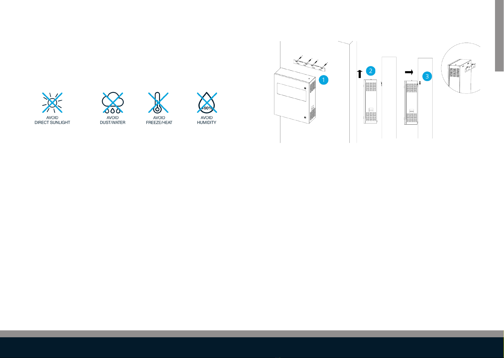
2.1.1. Mechanical installation 11
2.1.1.1. Positioning 11
2.1.1.2. Provisions 12
2.1.2. Electrical installation 13
2.1.2.1. Wiring instructions 14
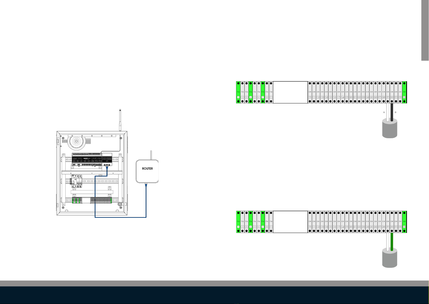
2.1.3. Network installation 15
2.1.4. DMX controller installation 16
2.1.5. RS485 controller installation 16
2.2. Conguration 17
2.2.1. System start-up 17
2.2.2.1 Account and permissions 17
2.2.2.2. DuraCloud - owner of the pool 18
2.2.3. Conguring other devices 19
2.2.4. Congure relays A & B 20
2.2.5. Congure input C as level sensor 20
2.2.6. LINK Touch pairing 20
2.2.7. Conguring smart rules 21
2.2.8. Conguring pool mode - Scheduler 22
2.3. Operation 26
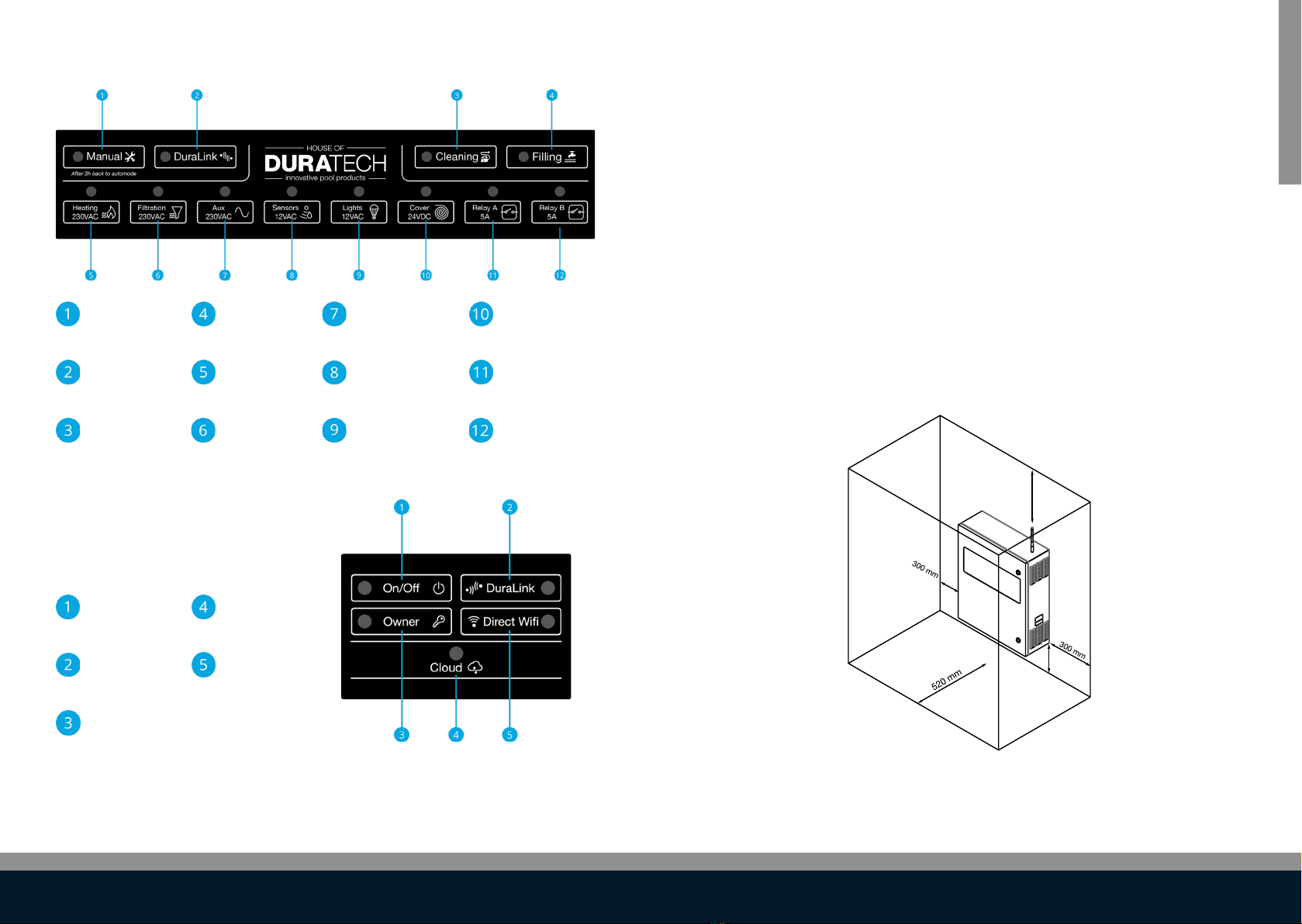
2.3.1. Keypad operation 26
2.3.1.1. Controller keypad 26
2.3.1.2. Gateway keypad 27
2.3.2. Discovery/Pairing mode 28
2.3.3. Automatic mode 29
2.3.4. Manual mode (service mode) 30
2.4. Updating 32
2.4.1. Controller 32
2.4.2. Gateway 32
2.5. Safety Conditions 33
3. Pool light 34
3.1. Installation 35
3.1.1. Wiring instructions 35
3.2.1. Lamp type selection 36
3.2.2. Pool light synchronisation 37
3.2.3. Manual pool light synchronization 37
3.3. Operation 38
3.3.1. LinkTouch 38

54
6.3.1.4. Key Switch 69
6.3.2. Multi-Brand Cover 70
6.3.2.1. Keypad 70
6.3.2.2. LINK Touch 70
6.3.2.3. DURACloud App 72
6.3.2.4. Key Switch 73
6.4. Updating 74
6.5. Safety conditions 75
7. DuraCloud 76
7.1. Installation 76
7.2. Conguration 76
7.3. Operation 76
7.3.1. Accessibility 76
7.3.2. Features 77
7.4. Updating 77

7
LINK MASTER
6
1. Introduction
1.1. About the LINK Master
Thank you for purchasing this House of DURATECH product. To ensure
proper operation, please read this manual carefully before using the device.
After reading this manual, be sure to keep it for future reference.
The LINK Master is a pre-wired central electrical hub, linking all technical
pool-related devices. It makes complex swimming pool installations eas-
ier to install and connect. Making it possible for dierent devices to work
together without adding dedicated cabling between these devices.
House of DURATECH devices are automatically recognized and set by de-
fault. You also have the possibility to add and connect Multi-Brand devices.
The LINK Master is equipped with multiple‘smart’ input and output connec-
tions for your pool devices. Giving you full access to the DuraLinkTM con-
nected range of products.
Connect the LINK Master to the internet and it will automatically connect to
the DuraCloud App and Portal for easy conguration and operation of the
dierent devices.
The LINK Master ensures ecient and safe operation of your pool.
Be aware that the LINK Master is an exact and sensitive system that must
always be handled with care. During installation, the regulations and provi-
sions applicable for the country and site of installation must be respected.

98
1.2. Box content
Check that the following parts are supplied with the product.
- 1 x Cabinet
- 1 x Wall mounting plate
- 2 x Cabinet door triangle keys
- 1 x Quick guide
- 1 x Fixing set (screws, plugs)
- 1 x Antenna
1.3. Keypad
High level overview of the LINK Master and the two keypads that are inside.
DLM-600
DLM-600

11
LINK MASTER
10
1.3.1. Controller keypad
Manual button Filling button Aux button Cover button
Used for switching between
manual and automatic
mode.
Used for enabling/dis-
abling the lling mode of
the pool.
Used for turning Auxiliary port
on or o. This button will open/
close the pool cover
DuraLink button Heating button Sensors button Relay A button
Used for enabling/disabling
discovery mode. Used for turning the heat
pump on or o.
Used for turning the sensors
on or o.
(By default this led is on.)
Used for activating your
Relay A function. (→
2.2.3.)
Cleaning button Filtration button Lights button Relay B button
Used for enabling/disabling
cleaning mode for the pool Used for turning the ltra-
tion pump on or o. Used for turning the pool lights
on or o.
Used for activating your
Relay B function (→
2.2.3.)
1.3.2. Gateway keypad
On/O button Cloud LED
This button will turn on/o
the gateway.
This led will be on if
your LINK Master has an
internet connection.
DuraLink LED Direct Wi button
This led will blink if it
receives a wireless DuraLink
message.
This button will enable
an access point on your
gateway.
Owner button
This button is used to
become owner in the Dura-
Cloud App (→ 2.2.2.2.)
2. LINK Master
2.1. Installation
2.1.1. Mechanical installation
2.1.1.1. Positioning
Important guidelines to observe when choosing the correct location for
installing the LINK Master.
- The antenna needs to be attached on the top right of the
LINK Master
- The LINK Master cabinet needs to be mounted vertically and
permanently on a solid wall with sucient bearing capacity.
- Respect a free space around the LINK Master cabinet for
unobstructed airow. (see drawing below)
300 mm
300 mm
DLM-600

13
LINK MASTER
12
- The location where the LINK Master will be installed must be
protected from dust and water in order to ensure that the device
functions properly.
- The ambient temperature must be between 0°C and +40°C and
must be as constant as possible.
- The relative humidity at the location of installation must not exceed
90%, no condensation may occur.
- Direct heat or sun rays on the device must be avoided. The LINK
Master is not suitable for outdoor installation.
- The DuraCloud App and LINK Touch need access to the
LINK Master for conguration of certain settings and calibrations.
- For the DuraCloud App to fully communicate with the LINK Master
it needs to be connected to a‘router’ device providing wireless
(cloud) access. (→2.1.3)
- For the LINK Touch to correctly communicate with the LINK Master
it needs to have an unblocked radio signal.
- Also be aware that for‘cover operation’ safety reasons the LINK
Touch may only be mounted in a place that allows full visibility of
the entire pool.
2.1.1.2. Provisions
Before commencing with the electrical installation, the following supplies
need to be available at the place of installation.
- Power supply 230VAC 32A
- Network cable
Make sure that the cable section (mm²) for the power cable is in accordance
with the cable length and complies with the applicable‘country’standards.
2.1.1.3. Phyisical installation
1. Fix the wall mounting plate to the wall using the included (plugs) and
screws.
2. Lift the Link Master up, and position in front of the hooks on the mount-
ing plate. (best with 2 persons)
3. Lower the Link Master and let the hooks slide into the holes on the back
of the cabinet.
Make sure the Link Master is securely attached.
DLM-600

15
LINK MASTER
14
2.1.2. Electrical installation
High level overview of the LINK Master and the parts that are inside.
DLM-600 overview
DLM-600 terminal blocks
2.1.2.1. Wiring instructions
Before opening the housing, it is necessary to always de-energize the de-
vice electrically. The electrical connection as well as the work of adjustment
and servicing should only be carried out by an qualied electrician!
- Check the sticker on the inside of the cabinet door for easy
installation. Connect all the devices to the connection terminals at
the bottom of the cabinet.
- Refer to each individual chapter (3-6) for device specic installation
instructions. Ensure all connections are stable by tightening the
connection terminal screws rmly.
- Connect the 230VAC power supply cable
- Ensure the correct connection of the grounding (terminal 1)
The DLM-600 may not not exceed 500VA and the current 42A
DLM-600 inside cabinet sticker
Antenna
Transformer
Gateway
Circuit
breakers
Terminal
Blocks
Controller

17
LINK MASTER
16
2.1.3. Network installation
For the DuraCloud App to communicate with the LINK Master it needs to be
connected to a‘router’device providing wireless (cloud) access. This access
is essential to be able to fully congure your LINK Master (→ 2.2)
The‘router’device cable should be connected in the LAN socket. (drawing
below)
2.1.4. DMX controller installation
The DMX controller can be connected to the LINK Master in the following
way.
Connect the DMX controller wires to the connection terminal blocks
29 and 30 on the DLM-600
For more information about how to use the DMX commands please refer to
(→3.3.5.)
DLM-600 DMX connection
2.1.5. RS485 controller installation
A controller with RS485 connection can be connected to the LINK Master in
the following way.
Connect the RS485 controller wires to the connection terminal blocks
29 and 30 on the DLM-600
For more information about how to use the RS485 commands please refer
to (→4.3.3.)
DLM-600 RS485 connection
DLM-600

19
LINK MASTER
18
2.2. Conguration
2.2.1. System start-up
For the initial start-up the LINK Master Controller and Gateway keypads will
be used because the DuraCloud App and LINK Touch are not yet paired with
the LINK Master.
Also be aware that the last step in the initial start-up of the Gateway is
to search for any software updates. This process is only possible when a
network connection with internet access has been established. If you have
opted for the local‘network’connection (→2.1.3.) this step in the start-up
will be skipped.
- Power up the LINK Master by switching on the power supply.
- On the keypad all Led’s will blink once short, to check their
functioning.
- On the controller keypad all Led’s of connected devices will stay
ON.
- On the gateway keypad the on/o button will start blinking for 30
seconds. This means it is starting up.
- Two minutes after start-up, the“DuraCloud” LED will show if the
LINK Master has made an internet connection (LED ON) or not (LED
OFF).
- When the internet connection is made, The LINK Master will now
search for any software updates.
- During the process of updating, the LINK Master will be fully
operational.
2.2.2. DuraCloud app pairing
2.2.2.1 Account and permissions
The DuraCloud App works around roles which have dierent levels of per-
mission. The roles have can have‘local’and/or ‘cloud’access to the LINK
Master.
Local access = Gateway specic anonymous accounts that require local
network access to be created.
Cloud access = User accounts that are created in the cloud and can be
linked to one or more gateways.
The below table gives an overview of the combinations.
Roles Obtained by Obtainable after Cloud Account Local Account
1 Guest Local request Connecting to gateway (Automatic) NO
YES
2
Owner
Pressing owner button
YES
3Other owner account - Promotion
- Activating web link
4 Installer PPS Certied by PPS NO
2.2.2.2. DuraCloud - owner of the pool
The DuraCloud App will give access to all options available for the congu-
ration of the pool in a smart and simple way.
Next is for the DuraCloud App to obtain the‘Owner role’for the pool.
- Ensure the smart phone or tablet you are using is connected to the
same network as the LINK Master.
- Open the DuraCloud App on your‘smart’device.
- Open the menu on the top left
- Navigate to“Claim Ownership”
- Select the Gateway keypad button“Owner”to obtain authorised
access.
- Click on the gateway in the DuraCloud App you want to promote
- When the DuraCloud App shows that it has become owner, the
procedure has successfully been completed.

21
LINK MASTER
20
2.2.3. Congure other devices
Before continuing with the pairing of the LINK Touch (→2.2.6.) it is import-
ant that all installed devices are correctly paired with the LINK Master.
- Pool lights (→3.2.)
- Heat pump (→4.2.)
- Filter pump (→5.2.)
2.2.4. Congure relays A & B
Before continuing with the conguration of the relays, please ensure the
DuraCloud App has established the owner role for the pool. (→2.2.2.2.)
- Ensure the DuraCloud App is connected to the same network as the
LINK Master.
- Open the DuraCloud App on your device
- Select the pool you wish to congure
- When the DuraCloud App has the owner role for this pool, a settings
icon will show in the top right corner.
- Click on the settings icon
- You can now change relays A & B to the preferred mode.
- Relay A
- OFF
- Open multi-brand cover
- Toggle
- Pulse
- FilterpumpBoost
- Relay B
- OFF
- Close multi-brand cover
- Toggle
- Pulse
- Filling
The available options for setting the relays are directly related to the
connected devices.
For example; when using the DuraCover both relay A and B remain free,
however when using a Multi-Brand cover both Relay A and B are assigned
for the opening and closing of the cover and cannot be used for any other
functionalities.
2.2.5. Congure input C as level sensor
Input C cannot be manually congured, it works according to the following
rules:
- The level sensor must be connected to input C (see technical
installation)
- The level sensor will only be active when relay B is set as“lling”
- The ling control system which is connected to the LINK Master will
be activated
2.2.6. LINK Touch pairing
To operate the LINK Master using the LINK Touch remote control, a con-
nection needs to be establish rst, by pairing the two devices.
- The“Pairing”mode will allow the LINK Touch to establish a wireless
connection with the LINK Master.
- During this pairing sequence the LINK Touch needs to be in close
proximity (<2m) of the LINK Master.
After completing this pairing sequence the LINK Touch will be able to ‘wire-
lessly’operate the installed House of DURATECH devices (Heat pump, Pool
lights and Cover) or similar multi-brand components (limited functions).
Steps for pairing:
- Press the DuraLink button on your controller keypad.
- The DuraLink button will switch ON and go in‘Pairing’mode for 15
minutes

23
LINK MASTER
22
- Warmup
– Once the heat pump has been deactivated, the heatpump
will still run about 15 minutes till full stop, to avoid damage
to the internal circuit of the heat pump
– when the lter pump is not running, the temperature
measurement in the heat pump will be aected by the
surrounding temperature. When this temperature diers
over 3 degrees (up or down) from the last known
temperature, the lter pump will be switched on for
5 minutes to start water circulation and re-measure the pool
water temperature.
2.2.8. Conguring pool mode - Scheduler
Depending on the pool mode, the controller will behave dierently. All
modes have their specic advantages.
These are our dierent pool modes:
- High
- Normal
- on/o
- Multi-brand inverter
- DURAFLOW inverter
- Eco
- on/o
- Multi-brand inverter
- DURAFLOW inverter
- OFF
- High
→Everything running at full power
Steps on LINK Touch for pairing:
- Click on this pair screen once on your LINK Touch display
Hold the screen for 3 seconds to
open the settings menu.
Touch the screen once to put the
LINK Touch in pairing mode.
SETTINGS
Pair start
- The LINK Touch will now start the pairing with the LINK Master
- When the pairing is successfully completed, the LINK Touch display
will show“Paired”.
2.2.7. Conguring smart rules
Smart rules are pre-programmed to automate processes of specic pool
devices installed to the LINK Master. The only manual option remaining is to
select, activate and to deactivate the Smart rules.
Smart Rules
- Adjust Filter pump speed when Cover is active
• Not boost – lter pump will run at normal speed when
opening and closing cover
• Disabled - Filter pump not inuenced when opening or
closing
• OFF – lter pump O when opening or closing
- Filter Pump in boost to vent the suction line
- Heat Pump - Is automatic, cannot be deactivated
- Cooldown - Once the heat pump has stopped the lter
pump will continue to run for an extra 5 minutes, water will
continue to circulate and extract all the remaining heat from
the heat pump.

25
LINK MASTER
24
NORMAL INVERTER
- Eco
→ Everything is running at a bare minimal to keep the pool clean
and warm. No automatic systems are allowed to work outside the
scheduled times.
ECO ON/OFF
- Normal
→Everyday use, the controller keeps the pool as clean and warm as
possible with the least amount of energy.
NORMAL ON/OFF
NORMAL MULTI-BRAND INVERTER

27
LINK MASTER
26
2.3. Operation
When the conguration has been completed the LINK Master is ready for
daily use. The LINK Master will standard and therefore in most cases be run-
ning in the automatic mode.
• Automatic mode (→2.3.3.)
Additional operation modes & informations are available and
explained in the following chapters.
• Pairing mode (→2.3.2.)
• Manual mode (→2.3.4.)
• Alerts and errors (→2.3.5.)
2.3.1. Keypad operation
2.3.1.1. Controller keypad
Manual button Filling button Aux button Cover button
Used for switching between
manual and automatic
mode.
Used for enabling/dis-
abling the lling mode of
the pool.
Used for turning Auxiliary port
on or o. This button will open/
close the pool cover
DuraLink button Heating button Sensors button Relay A button
Used for enabling/disabling
discovery mode. Used for turning the heat
pump on or o.
Used for turning the sensors
on or o.
(By default this led is on.)
Used for activating your
Relay A function. (→
2.2.3.)
Cleaning button Filtration button Lights button Relay B button
Used for enabling/disabling
cleaning mode for the pool Used for turning the ltra-
tion pump on or o. Used for turning the pool lights
on or o.
Used for activating your
Relay B function (→
2.2.3.)
ECO MULTI-BRAND INVERTER
ECO INVERTER
- O
→Everything is o

29
LINK MASTER
28
2.3.1.2. Gateway keypad
On/O button Cloud LED
This button will turn on/o
the gateway. This led will be on if your
LINK Master
DuraLink LED Direct Wi button
This led will blink if it
receives a wireless DuraLink
message.
This button will enable
an access point on your
gateway.
Owner button
This button is used to
become owner in the app
(ref. become owner)
2.3.2. Discovery/Pairing mode
The Pairing/Discovery mode is used to connect House of DURATECH devic-
es with the LINK Master. The LINK Master will be able to pair with all devices
part of the DuraLinkTM connected product range.
Enabling pairing/discovery mode:
This mode is enabled by pressing the Duralink button on the LINK Master
controller keypad. The pairing mode will be active for 15 minutes,
All the devices are powered o when entering the pairing mode.
The device pairing can be initiated by pressing on the device button on the
keypad. See the corresponding chapters in this manual to pair with a DURA-
HEAT Heat pump/DURAFLOW Filter pump/DURACOVER Cover/...
This pairing mode is also used to pair remote controls (e.g. LINK Touch
2.2.6. ).
The bottom row LEDs indicate if a device is successfully paired to the LINK
Master:
They indicate the following:
• OFF: no DuraLinkTM device connected to the LINK Master
• ON: DuraLinkTM device connected to the LINK Master
• SLOW BLINK: Pairing in progress
• 3 TIMES FAST BLINK: Pairing succeeded
Multi-Brand devices are connected manually which is describe in the chap-
ters for each individual device.

31
LINK MASTER
30
2.3.3. Automatic mode
By default the LINK Master is in Automatic mode. In this mode the LINK
Master will follow the schedule which is behind the selected Pool mode.
(→2.2.8.)
Returning to Automatic mode
• From Manual mode the LINK Master can go to Automatic mode by
pressing the MANUAL button on the keypad.
• From Pairing mode the LINK Master can go to Automatic mode by
pressing the DURALINK button on the keypad.
Using Cleaning in Automatic mode.
• Cleaning can be (de)activated via a short press on the keypad
cleaning button.
• When Cleaning is active, the following changes are made:
• Filter pump will be set in BOOST
• Purication will be disabled if congured as: `on ltration`
in the DuraCloud App pool settings.
• Cleaning will be disabled automatically after 6 hours.
Using Filling in Automatic mode.
• Filling is only available when Relay B is congured as Filling output
(→2.2.3.),if lling is activated without the correct conguration
of Relay B, the led will blink 3 times fast.
• When lling is active, the following changes are made:
• Filter pump is enabled.
• Filling valve is activated.
• The lling will automatically be disabled after 3 hours.
• Filling can manually be controlled by pressing the lling button on
the keypad or by a dedicated‘level’sensor sending a digital signal
(connected to input C).
When the‘level’ sensor is activated the signal sent to input C will enable
the lling cycle. This cycle enables lling for 3 hours followed by a stop of
9 hours. The 3 hours of lling will start again after the stop of 9 hours if the
signal for lling remained active. If the signal is no longer active it will stop
the cycle. A new lling cycle will start once a new signal is received.
2.3.4. Manual mode (service mode)
The Manual mode (service mode) is used to give manual access to each
individual device. The functioning of each device can be enabled or disabled
manually with the Keypad buttons, LINK Touch or DuraCloud App.
The Manual mode can be activated in two ways.
1. Pressing the button Manual will activate the Manual mode. This will
instantly disable/stop all devices and will give access to enable every
device manually.
2. When the LINK Master is in automatic mode, pressing any of these
buttons Heating/ Filtration/ Aux/ Sensors/ Relay A/ Relay B will
bring all devices in manual mode.
In the background the current states of all devices (Heating/ Filtration/ Aux/
Sensors/ Relay A/ Relay B) will be copied to the manual mode, and for the
button which was pressed the command will be executed.
Be aware that in manual mode devices will still switch ON other devices to
start operating correctly. (example; when manually switching on the heat
pump the lter pump will also be activated)
The LINK Master will continue to run in the Manual mode until this
mode is disabled by pressing the“manual”button on the keypad or
automatically disabled after 3 hours.
Using Cleaning in Manual mode.
• Cleaning can be (de)activated via a short press on the keypad
cleaning button.
• When Cleaning is active, the following changes are made:
• Filter pump will be set in BOOST
• Purication will be disabled if congured as: `on ltration`
• Cleaning will be disabled automatically after 6 hours.
All other devices will continue to work as set.

33
LINK MASTER
32
Using Filling in Manual mode.
• Filling is only available when Relay B is congured as Filling output
(→2.2.3.), if lling is activated without the correct conguration
of Relay B, the led will blink 3 times fast.
• When lling is active, the following changes are made:
• Filter pump is enabled.
• Filling valve is activated.
• The lling will automatically be disabled after 3 hours.
• Filling can in manual mode be controlled by pressing the
lling button on the keypad.
2.4. Updating
2.4.1. Controller
The LINK Master controller can be updated in two ways.
• The rst is an automated process whereby the rmware of the LINK
Master and all the devices will be updated when the gateway
receives a new rmware image, containing all the rmware of the
connected devices.
• The second is a manual procedure whereby an SD-card containing
the rmware update (LINK Master only) is inserted in the SD-card
slot on the controller board. (only available for authorized House of
DURATECH support sta)
o Update procedure:
- Turn OFF the LINK Master
- Insert µSD Card
- Turn on LINK Master
- LINK Master controller will update (8 bottom leds
will have a `wave` animation while updating)
- When the update is complete, the LINK Master will
automatically restart.
- You can remove the µSD card.
o NOTE: The manual procedure will only update the
LINK Master. It will NOT update the attached devices.
Be careful that the model versions of all devices are still
compatible with the updated LINK Master.
2.4.2. Gateway
The LINK Master gateway can also be updated.
• The gateway will automatically download, install, validate and
reboot itself when connected to the internet when a new rmware
version is available.

35
POOL LIGHT
34
3. Pool light
DuraVision oers four types of pool lights (model codes are listed) which
can be connected to the LINK Master. Each type has their own functionality,
with the PLC being fully compatible with all features available on the LINK
Master.
- ON/OFF controlled pool lights
- PLW WH
- PLP WH
- PLP WW
- DVM WH
- DVS WH
- PLP BL
- Slow Scene switching – Toggle pool lights (by LESS quickly, 1.1 sec
OFF time, turning them on/o)
- PLS RGB
- Fast Scene switching – Toggle pool lights (by quickly, 0.2 sec OFF
time, turning them on/o)
- DVM RGB
- DVS TW
- DVS RGB
- PLC - Power Line Communication controlled pool lights
- PLP TW
- PLP RGB
- DVP RGBW
When using Multi-Brand pool lights, one of the above corresponding type
of pool lights need to be selected. For example: Classic Halogen spots will
work with the ON/OFF controlled pool lights setting.
2.5. Safety Conditions
The LINK Master is tted with several safety features. They can be split in
two main categories.
- External
- Dierential switch 30mA
- Circuit Breakers
- Internal
- Current measurement on all 12V & 24V outputs of the
controller
- Software safety for maximum currents
- Automatic setting for maximum currents

37
POOL LIGHT
36
3.1. Installation
The pool lights are not allowed to exceed 450VA and the current 37.5A
3.1.1. Wiring instructions
There are two ways to wire the pool lights. Whereby the‘Star’connection is
the preferred one over the‘Daisy Chain’layout, for the best optimal perfor-
mance with the LINK Master.
Pool
house
Pool
Pool
house
Pool
Daisy chain connection Star connection
The pool light wires are connected to the assigned vision block. Ensure the
screws are rmly tightened!
DLM-600 pool light wiring
3.2. Conguration
The connected pool lights will automatically be selected by the LINK Master.
However we highly recommend verifying the settings and when needed
adjusting to the specic model pool light in the DuraCloud App. (→ 3.2.1.)
3.2.1. Lamp type selection
Please follow the below sequence:
- Open the DuraCloud App and ensure it has the owner role for the
relevant pool.
- Connect with the relevant pool for verifying/changing the setting.
- Click the settings icon on the top right of the DuraCloud App
screen.
- In the lamp settings the type of pool light can be switched.
- UNKNOWN (selected by default)
- PLW WH
- PLS RGB
- DVM WH
- DVM RGB
- DVS WH
- DVS TW
- DVS RGB
- PLP WH
- PLP TW
- PLP WW
- PLP BL
- PLP RGB
- DVP RGBW
When using Multi-Brand pool lights, the lamp needs to be selected from
one of the corresponding type of pool lights. For example: Classic Halogen
spots will work with the ON/OFF controlled pool lights setting. See full list
(→3.0)

39
POOL LIGHT
38
3.2.2. Pool light synchronisation
This synchronisation option is not used for ON/OFF pool lights and
PLC controlled pool lights
Synchronization is only required for the toggle pool lights, to ensure that all
pool lights are running the same color scene.
This process of synchronising the scenes generally takes 45 seconds to
complete.
Please follow the below sequence to synchronise the‘toggle’pool lights:
- Touch the display on the LINK Touch for 3 seconds
- This will activate the settings menu, use the arrow to navigate
- Go to menu“Lights setting enter”and touch the display to enter
- The display will show the option“On/O Sync start”
- Touch the display to activate this option. The lamps will go in a syn
chronisation mode, this will take about 45 seconds.
- Wait for all pool lights to turn the same color blue. This means the
synchronisation has successfully been completed.
3.2.3. Manual pool light synchronization
When the toggle pool lights get out of synchronisation and no longer dis-
play the same color, a manual synchronisation needs to be performed to
get the pool lights back into synchronisation. This manual synchronisation
can be triggered from the LINK Touch.
The manual synchronisation procedure entails the turning ON and OFF of
the pool lights in a specic time pattern. At the end of the manual synchro-
nization, the pool lights will go into the blue scene.
3.3. Operation
3.3.1. LinkTouch
The LINK Touch can be used to control the pool lights wirelessly, the LINK
Touch provides the following functions:
- Turning pool lights On/O
- Dimming of the pool lights (PLC pool lights only)
- Changing the color (only for RGB pool lights)
- Changing color scenes (predened by DuraVision)
- Changing CCT (Correlated Color Temperature) for RGB and TW
pool lights
Table of contents
Other Duratech DC Drive manuals
Popular DC Drive manuals by other brands

Rexnord
Rexnord Falk Quadrive A owner's manual

Thinkvert
Thinkvert TI120 Series user manual

Masterflex
Masterflex ISMATEC REGLO quick start guide

Unex
Unex MC-D-250-1000-050W-TW operating manual

TOX PRESSOTECHNIK
TOX PRESSOTECHNIK EQe-K Original operating instructions

ABB
ABB ACH580-01 Series Quick installation and start-up guide

Control Techniques
Control Techniques Unidrive LV Series installation guide

Lenze
Lenze L-force i700 Mounting instructions

Eaton
Eaton PowerXL DG1 Series VFD Instruction leaflet

Parker
Parker P1D-S installation instructions

Hansen
Hansen P4 Service manual

Allen-Bradley
Allen-Bradley PowerFlex 6000 installation instructions