Duratech LINK Touch DLT10-RGB User manual

DLT10-RGB/TW
Manual
(Other languages available online www.duratech.be)

2
Table of contents
Technical specifications
Box contents
About the LinkTouchTM
Installation instructions
Control functions: pool lights
Control functions: heat pump & pool cover
Advanced control functions: pool lights
Display: Status icons
Safety information
First use
How to use the Settings Menu
Connecting to ...
Cover operation settings
Buzzer settings
Temperature units display setting
Aux setting
Factory reset
Caring for the LinkTouchTM
Troubleshooting
PLP-REM(-300) compatibility
How to upgrade the PLP-REM(-300)
control board
Resetting the LinkTouchTM
Environment / disposal of old equipment
Service & warranty
Regulatory compliance
Page 3
Page 4
Page 4
Page 5
Page 6
Page 7
Page 8
Page 9
Page 10-11
Page 11
Page 12
Page 13
Page 14
Page 15
Page 16
Page 17
Page 18
Page 19
Page 19
Page 20
Page 21
Page 22
Page 23
Page 23
Page 23

3
Technical specifications
General specifications
Input Voltage: 5 V DC 0,5A
Interface: LoRa 868 MHz
USB-C
Ambient Air Temperature: 0°C to +40°C
Humidity 10% to 90% RH - non condensing
Ingress protection rate: IP20
IEC Protection Class: Class II
Size (in mm): 89,5 (Height)
186,5 (Width)
17,5 (Depth)
Weight: 298 g

4
Box contents
About the LinkTouchTM
The LinkTouchTM is the remote of your pool control system. By using the
Link Touch, you can control the lights, the heat pump and cover of your
swimming pool. The LinkTouchTM includes an integrated Li-Ion battery which
can be charged automatically when mounted onto the wall mount.
The LinkTouchTM connects wirelessly with a compatible Link Driver PLP-
REM(-300) and with DURA-V, DURA-Vi and DURAPRO heat pumps. Please
check our website for latest information regarding compatibility with heat
pumps
The LinkTouchTM can operate in dierent modes:
-
-
-
-
When the LinkTouchTM is inserted in the wall mount, it will charge till full
battery.
When LinkTouchTM is removed from the Wall mount, it will work instantly
when touched.
When the LinkTouchTM is removed from the Wall Mount and it is not touched
for 15 seconds, it will turn into “Standby mode”. In this case the display will
be o. As soon as the touch panel is touched by the user, the display will
turn on again.
When the battery is empty, the LinkTouchTM will no longer function. To turn
on the LinkTouchTM again, it needs to be inserted into the powered wall
mount. When inserted the display will be active again and the LinkTouchTM
will start communicating with the external devices.

5
Installation instructions
1.5m
The LinkTouchTM is powered using the included AC power adapter and USB
power cord
1. Plug the USB power cord into the power adapter
2. Plug the other end of the USB power cord into the USB-C connector
of the wall mount.
3. Plug the power adapter in a power outlet.
4. Mount the Link Touch onto the wall mount.

6
ON/OFF Lights:
Press to switch all Lights ON/OFF
Colour wheel:
Slide to change colour of Pool Lights
(only DLT10-RGB)
Colour program:
Press for previous colour program.
Colour program:
Press for next colour program.
Colour temperature:
Slide to the right to adjust the pool light
from “warm white” to “cool white”
Dimming level:
Slide to the right to increase
the brightness of the Pool Lights
Control functions: pool lights

7
Pool water Temperature UP:
Press to increase desired temperature
Pool cover OPEN:
Press and hold to open the pool cover.
When finger is removed from button
the cover will stop immediately
Pool cover CLOSE:
Press and hold to close the pool cover.
When finger is removed from the button,
the cover will stop immediately
ON/OFF heat pump:
Press to switch pool heat pump
ON/OFF
Pool water Temperature DOWN:
Press to decrease desired
temperature
NOTE:
Depending on AUX MODE, in settings
COVER OPEN/CLOSE or FUNC A/B
Control functions: heat pump & pool cover

8
ON/OFF Lights:
Press and hold for 1 second ON/OFF to see the
current settings
Activate the settings menu (*),
then use left arrow key to select the
desired setting.
Activate the settings menu (*),
then use right arrow key to select the
desired setting
(*) Touch the display for 3 seconds to
activate the settings menu.
Advanced control functions: pool lights

9
Battery:
Signal:
Heat pump:
Pool lights:
Relays A and B:
Pool cover:
Battery capacity
LinkTouchTM is communicating wirelessly
Pool heat pump is ON (idle)
Pool lights are connected
Relays A and B used, not the pool cover function
Pool cover is opening/closing
Pool cover is open
Pool heat pump is ON and heating/cooling
Pool lights are ON
There is an error with relays A and B (p.19)
Pool cover is closed
There is an error with the pool cover (p.19)
Pool heat pump has an error (p.19)
There is an error with the pool lights (p.19)
Battery is charging
Battery error (p.19)
Display: Status icons

10
Safety information
Intended use
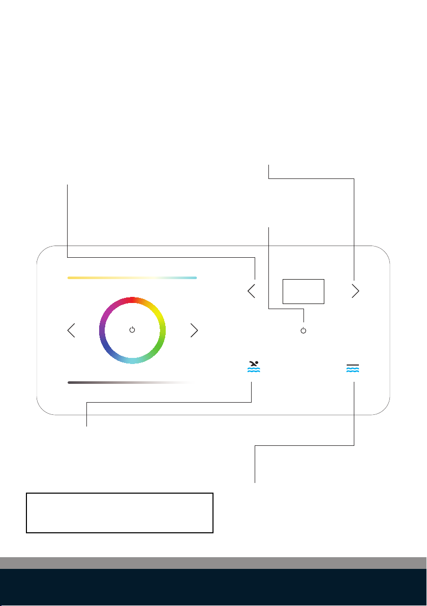
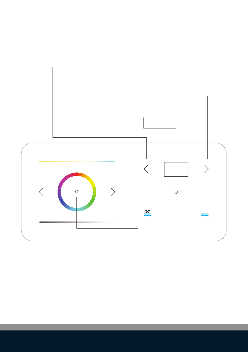
This device has been developed as a remote control for swimming pool
accessories. The LinkTouchTM should be used only for this purpose, as
described in this user guide.
Precautions for Setup
-
-
-
-
-
-
-
-
-
Precautions for Operation
-
-
-
-
-
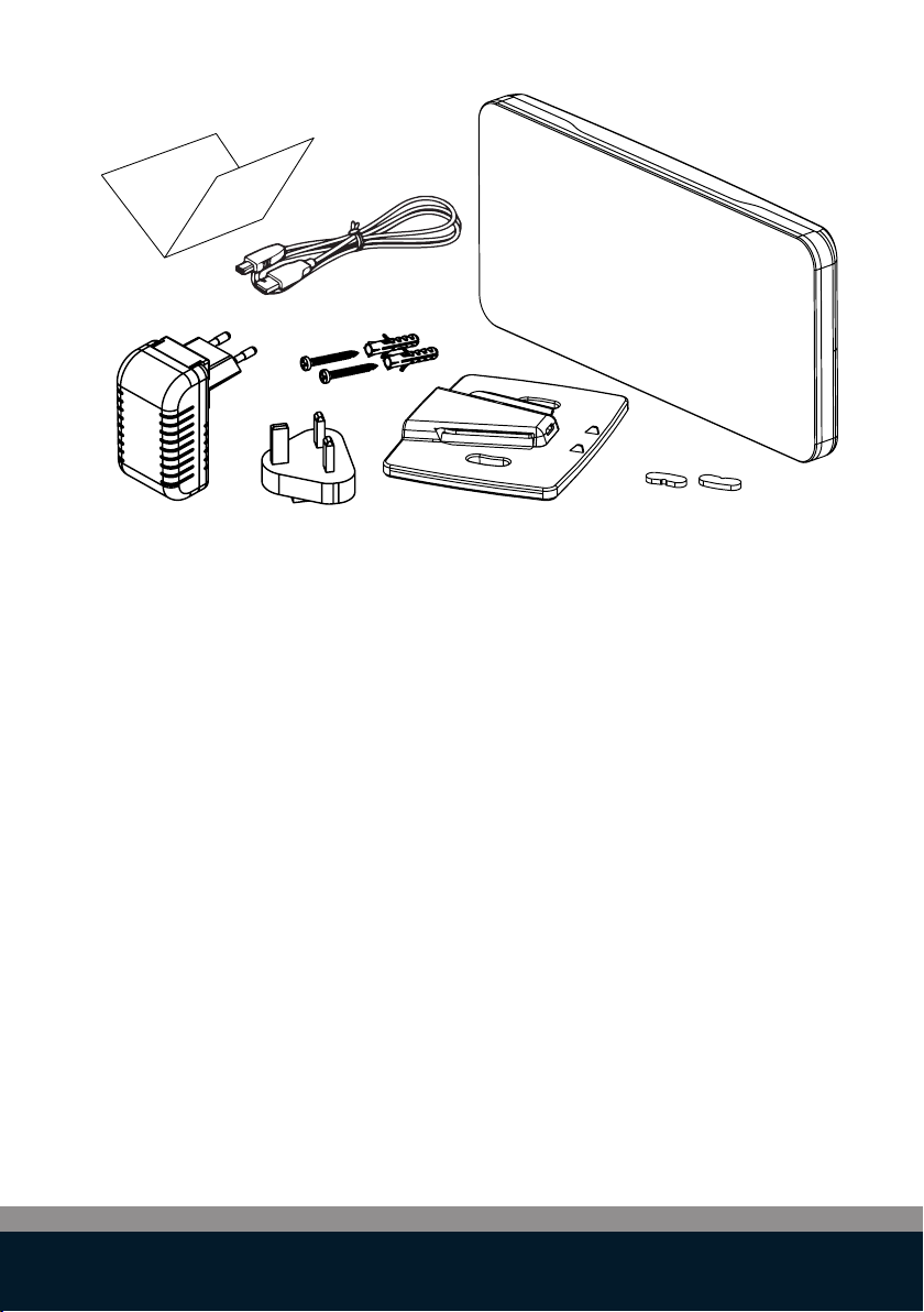
The LinkTouchTM can only be mounted indoor. Do not mount outdoors.
The power adapter is designed for 100 - 240V, 50/60 Hz. Verify if the
power outlet voltage is within this range before plugging in your power
adapter.
Install the device close to an accessible power outlet. Make sure the
power/USB cable can be easily disconnected from the power outlet at all
times.
Protect the power/USB cable and the power adapter from being strained
pinched or bucked.
Place the power/USB cable out of walk ways to prevent tripping over the
cable.
Use only the power adapter provided with the LinkTouchTM. Use of an
incorrect power adapter may cause overheating or fire.
Do not bend or place a heavy object on the power/USB cable as it could
damage the cable and result in risk of electric shock or fire.
Do not use the power/USB cable if damaged or frayed.
Be sure to hold only the connector end of the power/USB cable when
disconnecting. Repeated pulling on the cable will damage the cable.
Protect the LinkTouchTM from moisture and do not operate if power/USB
cable or plug are defective.
Never touch a power plug with wet hands.
Do not place anything on top of the LinkTouchTM.
Never spill liquid of any kind on the LinkTouchTM.
Do not drop or hit the LinkTouchTM.

11
Safety information
First use
Do NOT drop
the LinkTouchTM
Fully charge the LinkTouchTM
before using the device
The LinkTouchTM
is NOT water
proof
The LinkTouchTM
is NOT dust proof
Precautions for Cleaning, Transport and Storage
-
-
Use a soft, damp cloth to clean the exterior of the LinkTouchTM
Do not use cleaning tissues or chemical substances which might
damage the surface.
This LinkTouchTM contains no user serviceable parts. Do not attempt to
service the LinkTouchTM yourself. Repair service should be performed by a
authorised technician.

12
How to use the Settings Menu
3
SEC
Tap
Tap
Tap
Touch the display on the LinkTouchTM
for 3 seconds to go into the settings
menu.
Use arrow keys to select the desired
setting.
Touch the display once to confirm
the setting.
SETTINGS
SETTINGS
SETTINGS

13
Select “Pair Start”-mode from the
settings menu.
Touch the screen once to put the
LinkTouchTM in pairing mode.
Connecting to ...
This “Pairing”-mode will allow the LinkTouchTM to establish a wireless
connection with other devices such as :
- PLP-REM, PLP-REM-300, PLP-REM-450, linking per functionality
(lights, cover)
- The heat pump
Note : In case the PLP-REM-450 is already linked with cover and lights and
heat pump, it will distribute the links to the LinkTouchTM automatically.
Option 1:
Make sure the LinkTouchTM is in close proximity (<2m) of the device which
you would like to pair with wirelessly. Select “Pair Start” on the LinkTouchTM.
Power on the device.
The device will be in pairing mode for about 2 minutes after switched on.
The LinkTouchTM will now be pairing with the device.
Option 2: (only in combination with PLP-REM-450)
Connect the LinkTouchTM with the PLP-REM-450 using the USB cable. Select
“Pair start” on the LinkTouchTM. The LinkTouchTM will now be pairing with the
PLP-REM-450 and all linked devices (lights, cover and heat pump ) to it.
SETTINGS
Pair
start
Pairing

14
Cover operation settings
Go to “AUX SETTING” in the settings
menu.
Touch the screen and select “COVER”.
Go to “DEADMANSWITCH” in the
settings. Touch the screen to select
“DEADMANSWITCH ENABLED”.
There are 2 modes:
Deadman switch operation enabled:
The cover operation will run when pressing and holding the finger
on the button and will stop when releasing the finger from the button.
Deadman switch operation disabled:
The cover operation will run with a single touch of the button
and will stop when touching the button again.
SETTINGS
Aux setting
cover
SETTINGS
Aux setting
cover
SETTINGS
DeadManSwitch
enabled
Warning :
For safety reasons :
1.
2.
3.
Note that Propulsion systems cannot be held responsible for any damage or injury during the
operation of the cover.
The cover can only be operated when the remote device is connected to the wall
mount in case the “Deadman switch” operation mode is enabled.
The wall mount should be installed in close proximity of the pool to make sure that
when operating the cover with the remote device, the pool is always in sight of the
operator.
Note that the wall mount can only be mounted indoor. Do not mount outdoors.
The operator must ensure that the path for the cover is clear and nobody gets injured,
while operating the cover.

15
Buzzer settings
Go to “BUZZER” in the settings menu.
Touch the screen to select the
required operation mode. (note that
default setting is set to “BUZZER
ENABLED”.
The buzzer sound can be set to ON or OFF. If set to ON, then the buzzer
will sound each time as confirmation for touching any of the active areas
of the LinkTouchTM. The beep will also sound when the House of Duratech’s
DuraCover is in operation. In case of a third party cover, the beeping sound
will not be active.
Warning :
It is advised to set the buzzer setting to “ON”, in order to have an audio
feedback during the operation of the cover.
SETTINGS
Buzzer
Enabled
SETTINGS
Buzzer
Enabled

16
Temperature units display setting
Go to “TEMP °C/°F” in the settings
menu.
Touch the screen to select the
required units. (note that default
setting is set to “°C”.
The temperature units on the display can be set to Celsius or Fahrenheit
SETTINGS
Temp °C/°F
°C
SETTINGS
Temp °C/°F
°C

17
Aux setting
NOTE:
Repeat for “AUX MODE B”
Go to “AUX SETTING” in the settings
menu.
Touch the screen to select “AUX
SETTING AUXILIARY”.
Go to “AUX MODE A” in the settings
menu.
Touch the screen to select the
required mode “TOGGLE” or “PULSE”.
This setting will allow the installer to change the cover function to an
ON/OFF function for a dierent device.
The “Aux Setting” can be set to “Cover” or “Auxiliary”.
If set to “Cover” then the LinkTouchTM is considered to control a cover system.
If set to “Auxiliary” then the LinkTouchTM will control a dierent device with the
cover buttons and the buttons will act as an “ON” and “OFF” button.
SETTINGS
Aux setting
cover
SETTINGS
Aux setting
auxiliary
SETTINGS
Aux mode A
toggle

18
Factory reset
Go to “FACTORY RESET” in the
settings menu.
Touch the screen to reset the
LinkTouchTM to factory settings.
You can reset the LinkTouchTM to the factory default settings.
Resetting the LinkTouchTM reverts all settings to the factory default
settings. Any settings, including wireless connections, that have
been changed are lost.
The factory reset can be found in the setting menu.
SETTINGS
Factory reset
reset
SETTINGS
Factory reset
reset

19
Caring for the LinkTouchTM
Troubleshooting
The LinkTouchTM requires very little maintenance
-
-
This section includes information about what to do if you encounter
a problem with your LinkTouchTM. If you need further assistance,
please contact your installer or distributor or go to the support
section of the House of Duratech website at
www.duratech.be/duracare
You may occasionally need to clean the exterior of the housing.
To clean the exterior of the LinkTouchTM, wipe the exterior with
a soft, damp cloth.
NOTE: Do not use cleaning tissues or chemical substances
which might damage the surface
Don’t place the LinkTouchTM in direct sunlight
Battery error
Heat pump error
Pool light error
Aux error
Cover error
remove from heat source or take out of sunlight
consult manual of heat pump for trouble shooting
consult manual of pool light for trouble shooting
consult manual of auxiliary connected device for
trouble shooting
consult manual of cover for trouble shooting

20
PLP-REM(-300) compatibility
NOT upgradable
control board
upgradable
control board
After the firmware upgrade of the PLP-REM(-300), the handheld remote
control is no longer compatible with the PLP-REM(-300). In case a compatible
handheld remote control is required, then this one can be ordered separately.
To control the lights and the cover system, the LinkTouch™ communicates
with the PLP-REM(-300).
If your PLP-REM(-300) has the sticker “ LinkTouch™ ready”, then you do not
need to take any action. In this case the LinkTouch™ can work with the PLP-
REM(-300).
In case the PLP-REM(-300) does not have a “LinkTouch™ ready” sticker, then
your PLP-REM(-300)-requires a firmware update.
See below picture of the control boards of the PLP-REM(-300), which
are upgradable with an SD card, that is included in the packaging of the
LinkTouch™.
Other manuals for LINK Touch DLT10-RGB
1
This manual suits for next models
1
Table of contents
Popular Lighting Equipment manuals by other brands

Whelen Engineering Company
Whelen Engineering Company T-103 installation guide

ASTRO
ASTRO ENNA 1058 Series manual

Amico
Amico ice 30m Installation and operation instructions

Lightolier
Lightolier CTS3-3 specification

Larson Electronics
Larson Electronics EPLC2-LED-150W-RT-DNS instruction manual

HEPER
HEPER LL2044.862-EN Installation & maintenance instructions