DURAVANT QC CONVEYORS PF52 Instruction manual

PF52 Conveyors
Installation, Operation, & Maintenance Manual /
Manuale d’installazione, istruzioni per l’uso e per la manutenzione
Contents / Sommario
Warnings / Avvertenze 2
Controller / Controllore 4
Conveyor Installation / Installazione del trasportatore 5
Commissioning / Messa in servizio 7
Operation / Funzionamento 12
Maintenance / Manutenzione 16
Tension & Tracking / Tensione e allineamento 17
Troubleshooting / Risoluzione dei problemi 24
Exploded Views / Viste esplose 29
EC Declaration of Conformity / Dichiarazione di conformità CE 38
Service Record / Documentazione manutenzione 43
Original Language: English / Inglese
Translations from Original Language: Italian / Italiano
QC Conveyors
4057 Clough Woods Dr.
Batavia, OH 45103 USA
+1 (513) 753-6000
mcdonalds.qcconveyors.com

2PF Conveyors | Installation, Operation & Maintenance Manual
Warnings / Avvertenze
EN When used improperly, the con-
veyor rollers can pinch or maim.
Lock out power before servicing
the conveyor.
Do not use with the clear plastic
guards removed.
Risk of electric and re.
IT Se usati in modo improprio, i rulli del
trasportatore possono creare pizzica-
mento o provocare ferite
Prima di eseguire la manutenzione,
scollegare l’alimentazione
Non usare se le protezioni non sono
in posizione
Rischio di folgorazione o incendio
DANGER
PERICOLO
WARNING
AVVERTIMENTO
WARNING
AVVERTIMENTO
WARNING
AVVERTIMENTO
EN Climbing, sitting, walking, or riding
on the conveyor at any time could
result in severe injury or death.
KEEP OFF.
Exposed, moving parts can cause
severe injury. DISCONNECT
POWER before removing the clear
plastic guards.
The equipment may start without
warning and can cause severe
injury. KEEP AWAY.
Servicing equipement that is mov-
ing or energized can cause severe
injury. LOCK OUT POWER prior to
performing maintenance.
IT Salire, sedere, camminare o
farsi trasportare dal trasportatore in
qualunque modo può causare lesioni
gravi o morte
Parti mobili non protette possono
causare lesioni gravi; SCOLLEGARE
L’ALIMENTAZIONE prima di rimuove-
re le protezioni
L’apparecchiatura può essere attivata
senza preavviso e può causare le-
sioni gravi. TENERSI FUORI DELLA
PORTATA
La manutenzione dell’apparecchiatura
mentre è in movimento o quando è
connessa all’alimentazione può cau-
sare lesioni gravi. DISCONNETTERE
L’ALIMENTAZIONE.

PF Conveyors | Installation, Operation & Maintenance Manual 3
Tools and Supplies / Utensili e forniture
uTools and Supplies / Utensili e forniture
EN Wrench set:
13 mm, 10 mm, and 5.5 mm
Screwdrivers:
(1) small at head, (1) large at
head, (1) large phillips head
Torque wrench with an 8 mm
socket (Range 2-8 Nm)
5 mm metric allen wrench
IT Set di chiavi (13 mm, 10 mm e 5,5
mm)
Cacciaviti grande e piccolo a testa
piatta e cacciavite grande a croce
Chiave dinamometrica con una testa
da 8 mm (gamma da 2 a 8 Nm)
Chiave a brugola da 5 mm
EN Cleaning supplies:
cleaner and towels
Anti-Seize Removable threadlocker Ratchet with an 8 mm socket
IT Prodotti per la pulizia (detergente,
salviette)
Lubricante antigrippaggio Frenaletti rimovibile Cricchetto e testa da 8 mm

4PF Conveyors | Installation, Operation & Maintenance Manual
Controller Installation /
Installazione del dispositivo di controllo
Lock-out power. Emergency stops are not included with control panels or conveyors. Emergency stops are required and must be installed as part of the tables. The
circuitry for the emergency stop is integrated into the conveyor’s control panel and requires a modular male connector. In addition, the installer must provide a
lockable means of power isolation.
I dispositivi di interruzione d’emergenza dell’alimentazione non sono inclusi nei pannelli né nei trasportatori. I pulsanti di arresto d’emergenza (Emergency stop) sono obbliga-
tori e devono essere installati come parte dei tavoli. La circuiteria per i pulsanti di arresto d’emergenza è integrata nel contenitore del dispositivo di controllo del trasportatore
e richiede un connettore maschio modulare. Inoltre, l’installatore deve fornire un sistema di isolamento dell’alimentazione con serratura.
WARNING: Due to the risk of electric shock, maintenance on the control panel should be performed ONLY by service technician’s or licensed electrician’s.
AVVERTENZA: A causa del rischio di folgorazione, la manutenzione all’interno del pannello di controllo deve essere effettuata ESCLUSIVAMENTE da un tecnico della
manutentore o da un elettricista qualicato.
uControl Panel Install / Installazione del pannello di controllo
START
RESET
STOP START
RESET
STOP
x4x4 x4x4
EN
1Ensure the use of a 230V AC,
single phase power source.
WARNING
Risk of Electric Shock and Fire.
2Remove the clear cover from
control panel. 3Disconnect the clear cover
connector and set the cover
aside.
4Attach the panel to the table
using the 5 mm hex key and
the screws located in the panel
cover mounting holes.
IT Utilizzare alimentazione monofase a
230 V c.a.
AVVERTENZA
Rischio di folgorazione o incendio
Rimuovere la copertura trasparente
dal pannello di controllo
Scollegare il connettore con copertura
trasparente e conservare la copertura
a parte
Collegare il pannello al tavolo con la
chiave a brugola da 5 mm e con le
viti negli appositi fori della copertura
del pannello
START
RESET
STOP START
RESET
STOP
x4x4
EN
5Reconnect clear cover
connector. 6Secure clear cover to control
panel. 7Connect power cable to
controller. 8Connect emergency stop
cable to controller .
IT Collegare nuovamente il connettore
con copertura trasparente
Fissare la copertura trasparente al
pannello di controllo
Collegare il cavo dell’alimentazione al
dispositivo di controllo
Collegare il cavo del pulsante di
arresto d’emergenza al dispositivo di
controllo

PF Conveyors | Installation, Operation & Maintenance Manual 5
Conveyor Installation / Installazione del trasportatore
Lock-out power. Emergency stops are required and must be installed as part of the tables. The circuitry for the emergency stop is integrated into the conveyor’s
control panel. In addition, the installer must provide a lockable means of power isolation.
l’alimentazione. I pulsanti di arresto d’emergenza (Emergency stop) sono obbligatori e devono essere installati come parte dei tavoli. La circuiteria per i pulsanti di arresto d’e-
mergenza è integrata nel contenitore del dispositivo di controllo del trasportatore. Inoltre, l’installatore deve fornire un sistema di isolamento dell’alimentazione con serratura.
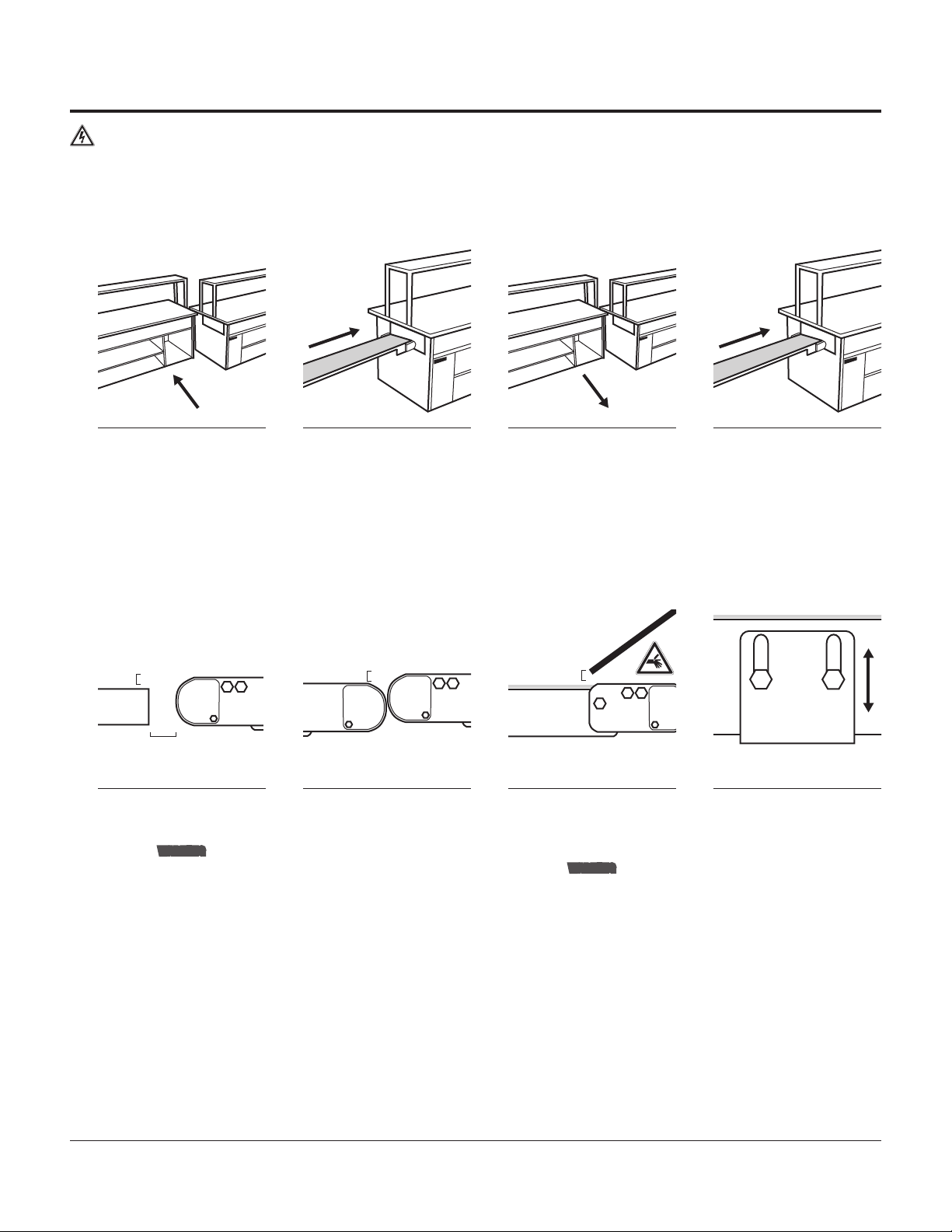
uInstall Conveyors In Tables / Installazione dei trasportatori nei tavoli
EN
1Separate the tables so the
service cavity within the ECU
table is accessible.
2Slide the ECU conveyor, tail
first, into the ECU table. 3Move the tables back to-
gether to allow access to the
PREP tables service cavity.
4Slide the PREP conveyor, tail
first, into the PREP table.
IT Separare i tavoli in modo da rendere
accessibili le aperture di servizio nei
tavoli ECU
Inlare il trasportatore ECU nel tavolo
ECU, inserendo la parte posteriore
per prima
Riavvicinare i tavoli consentendo
l’accesso all’apertura di preparazione
Inlare il trasportatore del tavolo di
preparazione nel tavolo di prepara-
zione, inserendo la parte posteriore
per prima
uCheck Conveyor Elevations / Regolazione dell’altezza dei trasportatori
3-5mm
25mm
OAT
3-5mm 3-5mm
EN
1Confirm the discharge end of
the ECU table conveyor is 3-5
mm above the OAT surface.
WARNING
Leave a 25 mm gap between the
conveyor and the OAT; a smaller
gap creates a pinch hazard.
2Confirm that the conveyors
transition point, at the end of
the PREP table, is 3-5 mm above
the ECU table. The conveyor bear-
ing housings should be between
0-5 mm apart at transition.
3Confirm that the top of the
PREP tables’ conveyor belt
is 3-5 mm below the bottom of
the chute.
WARNING
The chute and conveyor create
a pinch point; proper guarding
must be installed.
4Make adjustments as needed.
The mounting height can be
adjusted by loosening the hex head
screws with a 10 mm wrench.
IT Assicurarsi che il punto di scarico del
trasportatore del tavolo ECU si trovi
da 3 a 5 mm sopra la supercie del
tavolo di assemblaggio dell’ordine
(OAT)
AVVERTENZA
Lasciare 25 mm tra il trasportatore
e il tavolo di assemblaggio dell’or-
dine (OAT): uno spazio inferiore
crea il rischio di pizzicamenti
Assicurarsi che i trasportatori nel
punto di transizione del trasportatore
del tavolo di preparazione si trovino
da 3 a 5 mm più in alto rispetto al
trasportatore ECU. Gli alloggiamenti
dei cuscinetti del trasportatore
dovrebbero essere distanti tra 0 e 5
mm nel punto di transizione.
Assicurarsi che la parte superiore del
nastro del trasportatore del tavolo di
preparazione sia da 3 a 5 mm sotto la
base dello scivolo
AVVERTENZA
Lo scivolo e il trasportatore
creano un punto ad alto rischio di
pizzicamento. Installare protezioni
adeguate
Effettuare le regolazioni secondo le
necessità. L’altezza di montaggio può
essere regolata allentando le viti a
testa esagonale usando una chiave
da 10 mm

6PF Conveyors | Installation, Operation & Maintenance Manual
uInstall Clear Plastic Guards / Installazione delle protezioni
1
x4x4
1
EN
1Ensure that all twist nuts are
in the vertical position. 2Match the clear plastic guard
numbers with the correspond-
ing numbers on the conveyor
(4 clear plastic guards for each
conveyor).
3Install all 4 clear plastic
guards over the twist nuts
and onto the conveyor.
4Twist all of the nuts to the
horizontal, locked position.
IT Assicurarsi che tutti i dadi girevoli
siano in posizione verticale
Far corrispondere i numeri sulle prote-
zioni ai numeri sul trasportatore (4
protezioni per ogni trasportatore)
Installare tutte e 4 le protezioni sopra i
dadi girevoli e sopra il trasportatore
Girare tutti i dadi in posizione orizzon-
tale (bloccata)
Repeat this procedure for the second conveyor.
Ripetere la procedura per il secondo trasportatore.
uConnecting Conveyors to Controllers Collegamento dei trasportatori ai dispositivi di controllo
START
STOP
RESET
x2
EN
1Connect the ECU conveyor to
the control panel using the
ECU wire connector on the control.
2Connect the PREP conveyor
to the control panel using the
PREP wire connector on the control.
3Remove the plastic cover on
control, turn the circuit brea-
ker on, and remove the wire ties
from the face plates. Then replace
the plastic cover.
4Turn the control switch on
both the PREP and the ECU
tables to the <RESET> ( ) posi-
tion and release.
IT Collegare il trasportatore ECU al
pannello di controllo usando i con-
nettori dei cavi ECU sul dispositivo
di controllo
Collegare il trasportatore PREP al
pannello di controllo usando i con-
nettori dei cavi PREP sul dispositivo
di controllo
Rimuovere il coperchio di plastica dal
controllore,
Ruotare l’interruttore di controllo
sui dispositivi di controllo del tavolo
PREP ed ECU sulla posizione di reset
e rilasciarli ( )
Conveyors are now ready for commissioning.
I trasportatori sono ora pronti per la messa in servizio.

PF Conveyors | Installation, Operation & Maintenance Manual 7
Commissioning / Messa in servizio
uChecking Controller / Verica del dispositivo di controllo
START
STOP
RESET
EN
1Verify the power to the control
panel and both controls
display “0”.
2Turn the control switch to
<START>
( )
.3Verify the conveyor belt is
moving towards the OAT /
front of the kitchen.
4The control will read 1800
(factory default) or the speed
to which it has been set.
IT Vericare che l’alimentazione al
pannello e a entrambi i dispositivi di
controllo sia pari a 0
Ruotare l’interruttore del dispositivo di
controllo su Start (Avvio)
Vericare che il nastro sul trasporta-
tore si stia muovendo verso il tavolo
di assemblaggio dell’ordine (OAT) /
verso la parte anteriore della cucina
Il dispositivo di controllo visualizzerà
1800 (valore predenito di fabbrica) o
la velocità alla quale è stato impostato
START
STOP
RESET
EN
5Create an error by discon-
necting the control cable
from the motor.
6Verify the control displays
AL42. 7Turn the control switch to
<STOP>
().
8Reconnect the control cable.
IT Simulare un errore scollegando il
cavo di controllo dal motore (connet-
tore più piccolo)
Vericare che il controllore visualizzi
AL42
Ruotare l’interruttore del dispositivo di
controllo su Stop (Arresto) ( )
Ricollegare il cavo di controllo
Repeat this procedure for the second conveyor.
Ripetere la procedura per il secondo trasportatore.
If the alarm condition does not clear, refer to the manufacturer’s manual for the control.
Se l’allarme non scompare, consultare il manuale del produttore del dispositivo di controllo.

8PF Conveyors | Installation, Operation & Maintenance Manual
uChecking Controller (continued) / Verica del dispositivo di controllo (continua)
START
STOP
RESET START
STOP
RESET
EN
9Turn the control switch to
<RESET> ( ) to clear the
error.
10Verify the control displays
“0”. 11Turn the control switch to
<START> ( ). 12
Ensure the conveyor belt is
running.
IT Ruotare l’interruttore di controllo su
Reset
( ) per eliminare l’errore
Vericare che il controllore visualizzi 0 Ruotare l’interruttore del dispositivo di
controllo su Start (Avvio) ( )
Assicurarsi che il trasportatore sia in
funzione
If the conveyor does not start, the clear plastic guards may not be making contact with the sensors; or the emergency stop could be activated. Check all of the clear
plastic guards for proper placement and verify that all of the twist nuts are in the horizontal, locked position. Also, ensure the emergency stop is deactivated.
Se il trasportatore non si avvia, verificare che le protezioni di plastica facciano contatto con i sensori; verificare inoltre che il pulsante di arresto d’emergenza non sia
attivato. Controllare che tutte le protezioni siano posizionate correttamente ed assicurarsi che tutti i dadi girevoli siano nella posizione bloccata (orizzontale). Assicurarsi
inoltre che il pulsante di arresto d’emergenza sia disattivato.
Repeat this procedure for the second conveyor.
Ripetere la procedura per il secondo trasportatore.
If problems occur, please refer to the “Troubleshooting” section on page 24 of this manual for corrective actions.
Se si verificano problemi, consultare la sezione Risoluzione dei problemi di questo manuale (pagina 24) per le azioni correttive.

PF Conveyors | Installation, Operation & Maintenance Manual 9
uTest Clear Plastic Guard Sensors / Test dei sensori delle protezioni
Each
clear plastic guard
must be tested individually.
Ogni protezione deve essere testata individualmente.
START
STOP
RESET
EN
1Remove a clear plastic guard
while the conveyor is running. 2Ensure the conveyor has
stopped and that the power
is off to the control panel. If the
power remains on or the conveyor
continues running, refer to the
“Troubleshooting“ section of this
manual on page 24.
3Replace the clear plastic gu-
ard by sliding it over the twist
nuts. Turn the nuts to the horizontal
position to lock in place.
4Turn the control switch to
<STOP>
().
IT Rimuovere una protezione mentre il
trasportatore è in funzione
Assicurarsi che il trasportatore si sia
arrestato e che l’alimentazione del
pannello sia stata disinserita. (Se
l’alimentazione è inserita o il traspor-
tatore è in funzione, fare riferimento
alla sezione Risoluzione dei problemi
di questo manuale)
Sostituire la protezione facendola
scorrere sui dadi girevoli e ruotando
i dadi in posizione orizzontale per
bloccarli in posizione
Ruotare l’interruttore di controllo su
Stop (Arresto) ( )
START
STOP
RESET
EN
5Turn the control switch to
<START>
().
6Ensure the conveyor is
running. 7
Repeat these steps for
each clear plastic guard
on the conveyor.
IT Ruotare l’interruttore di controllo su
Start (Avvio) ( )
Assicurarsi che il trasportatore sia in
funzione
Ripetere le operazioni per ogni
protezione sul trasportatore
If the conveyor does not start, the clear plastic guards may not be making contact with the sensors; or the emergency stop could be activated. Check all of the clear
plastic guards for proper placement and verify that all twist nuts are in the horizontal, locked position. Also, ensure the emergency stop is deactivated.
Se il trasportatore non si avvia, verificare che le protezioni di plastica facciano contatto con i sensori; verificare inoltre che il pulsante di arresto d’emergenza non sia
attivato. Controllare che tutte le protezioni siano posizionate correttamente ed assicurarsi che tutti i dadi girevoli siano nella posizione bloccata (orizzontale). Assicurarsi
inoltre che il pulsante di arresto d’emergenza sia disattivato.
Repeat this procedure for the second conveyor.
Ripetere la procedura per il secondo trasportatore.
If problems occur, please refer to the “Troubleshooting” section on page 24 of this manual for corrective actions.
Se si verificano problemi, consultare la sezione Risoluzione dei problemi di questo manuale (page 24) per le azioni correttive.

10 PF Conveyors | Installation, Operation & Maintenance Manual
uTest Transitions & Speed / Test delle transizioni e della velocità
EN
1Start both conveyors and drop
a filled sandwich box into the
chute of the PREP table.
2Adjust the conveyor heights
as necessary for optimal
transitions.
3Adjust the conveyor speed,
faster or slower, until the
sandwich box lands in the optimal
spot on the OAT. (see the “Speed
Adjustment” section at the top of
page 13)
4Test the sandwich box several
times; checking the transi-
tions between the chute, conveyors,
and the OAT.
IT Avviare entrambi i trasportatori e
posare un contenitore dei panini
pieno nello scivolo del tavolo di
preparazione
Modicare le altezze del trasporta-
tore quanto necessario per ottenere
transizioni ottimali
Regolare la velocità del trasportatore,
aumentandola o diminuendola, no
a quando il contenitore dei panini
cade in un punto ottimale sul tavolo di
assemblaggio dell’ordine (vedere la
sezione Regolazione della velocità)
Testare il contenitore dei panini varie
volte, vericando le transizioni tra lo
scivolo, i trasportatori e il tavolo di
assemblaggio dell’ordine (OAT)
If test boxes hit underside of table, more adjustments may be needed to the conveyor height.
Se i contenitori di prova urtano la parte inferiore del tavolo, potrebbero essere necessarie ulteriori regolazioni dell’altezza del trasportatore.
uTest Emergency Stop / Test degli arresti di emergenza
EN
1While the conveyor is running,
press the emergency stop. 2Ensure that the conveyor
stops running. 3Reset the emergency stop
by twisting the button to the
depressed position.
IT Con il trasportatore in funzione,
premere l’arresto di emergenza
Assicurarsi che i trasportatori si
arrestino
Reimpostare l’arresto di emergenza
ruotando il pulsante sulla posizione
abbassata

PF Conveyors | Installation, Operation & Maintenance Manual 11
uComplete Commissioning / Completare la messa in servizio
36 PF45 Conveyors | Installation, Operation & Maintenance Instructions
Service Record
Service Record / Service Record
Date Service Performed
uSerial Numbers
Prep Table Conveyor:
_________________________________
ECU Table Conveyor:
_________________________________
uDate of Installation
________________________________________________
PF45 Conveyors
Installation,Operation & Maintenance Instructions
QCIndustries,LLC
4057CloughWoods Dr.
Batavia,OH45103 USA
+1(513)753-6000
qcconveyors.com
Contents
Contents/ Contents
Warnings/Warnings / Warnings 2
Uncrating/Déballage / Auspacken 3
Installation/Installation / Installation 4
Operation/Operation / Operation 10
Controller/Controller / Controller 14
Tension&Tracking /Tension & Tracking /Tension & Tracking 15
Maintenance/Maintenance / Maintenance 17
MaintenanceChecklist/ Maintenance Checklist / Maintenance Checklist 24
ExplodedViews/ Exploded Views /ExplodedViews 26
ECDeclarationof Conformity 33
ECDeclarationof Conformity 34
ECDeclarationof Conformity 35
ServiceRecord / Service Record / Service Record 36
OriginalLanguage:English
TranslationsfromOriginal Language: French, German
EN
1If removed, replace the clear
plastic guard(s) by sliding
over the twist nuts at the cor-
responding number on the conveyor.
Turn the nuts to the horizontal
position to lock in place.
2Record the serial numbers
for the emergency panel and
all conveyors on the back cover of
this manual.
3File this manual in the store
office for future reference.
IT Se rimosse, rimettere le protezioni
facendole scorrere sui dadi girevoli
nelle posizioni corrispondenti ai
relativi numeri e ruotando i dadi in
posizione orizzontale per bloccarli in
posizione
Registrare il numero di serie sulla
retrocopertina del presente manuale
Conservare il manuale nell’ufcio per
riferimento futuro

12 PF Conveyors | Installation, Operation & Maintenance Manual
Operation / Funzionamento
uStarting / Avviamento uStopping / Arresto
START
STOP
RESET START
STOP
RESET
EN
1Start the conveyor by turning
the control switch to <START>
().
1Stop the conveyor by turning
the control switch to <STOP>
().
IT Avviare il trasportatore ruotando
l’interruttore di controllo su Start
(Avvio)( )
Arrestare il trasportatore ruotando
l’interruttore di controllo su Stop
(Arresto)( )
If the conveyor does not start, check that all of the clear plastic guards are in place and that the emergency stops are in the depressed position. If the conveyor still does
not start, refer to the “Troubleshooting” section of this manual on page 24.
Se il trasportatore non si avvia, controllare che tutte le protezioni siano in posizione e che gli arresti di emergenza siano in posizione premuta. Se il trasportatore non si avvia
nemmeno ora, controllare la sezione Risoluzione dei problemi di questo manuale.
uResetting / Reimpostazione (Reset)
START
STOP
RESET START
STOP
RESET
EN
1If an alarm condition occurs,
the control must be reset. 2Turn the control switch to
<RESET> () and hold for
one second.
3If the control displays “0”,
the alarm has been cleared. 4Start the conveyor by turning
the control switch to <START>
().
IT Se si verica un allarme, è necessario
reimpostare il dispositivo di controllo
Ruotare l’interruttore di controllo su
Reset ( ) e mantenerlo in tale
posizione per un secondo
Se il dispositivo di controllo visualizza
“0”, l’allarme è stato cancellato
Avviare il trasportatore ruotando
l’interruttore di controllo su Start
(Avvio)( )
If the alarm condition does not clear, refer to the manufacturer’s manual for the controller.
Se l’allarme non scompare, consultare il manuale del produttore del dispositivo di controllo.

PF Conveyors | Installation, Operation & Maintenance Manual 13
uSpeed Change / Cambio di velocità
The speed has been pre-programmed to 1800 rpm. This can be changed depending on operational needs once the conveyor is installed. If the control will not change speed, the
control may be locked. Refer to the “Unlocking Controller” procedure below.
La velocità è preimpostata a 1800 giri al minuto. Dopo l’installazione del trasportatore, tale valore può essere modicato in base alle necessità di funzionamento. Se il dispo-
sitivo di controllo non cambia velocità, il dispositivo di controllo potrebbe essere bloccato. Fare riferimento alla procedura di Sblocco del dispositivo di controllo più in basso.
START
STOP
RESET START
STOP
RESET
EN
1Turn the control switch to
<STOP>
( )
and open the
plastic cover on the control panel
(do not disconnect).
2Rotate the dial on the control
until the desired speed is
displayed.
3Press the dial to set the
speed. 4Replace the plastic cover
on the control panel and
turn the control switch to <START>
().
IT Ruotare l’interruttore di controllo
su Stop (Arresto) ( ) e aprire il
coperchio di plastica sul contenitore
del dispositivo di controllo (non
disinserirlo)
Ruotare il selettore sul dispositivo di
controllo nché viene visualizzata la
velocità desiderata
Premere il selettore per impostare
la velocità
Riposizionare il coperchio di plastica
sul contenitore del dispositivo di con-
trollo e ruotare l’interruttore Start/Stop
(Avvio/Arresto) su Start (Avvio) ( )
uUnlocking Controller / Sblocco del dispositivo di controllo
In normal operation the control should not be locked, but can become locked accidentally.
In condizioni di funzionamento normale, il dispositivo di controllo non dovrebbe essere bloccato, ma può bloccarsi accidentalmente.
EN
1Press ‘mode’ once to reveal
“non” and allow the unlocking
procedure.
2Hold ‘mode’ for 5 seconds
and wait for the display to
flash “UnLK” and return to “non”.
3Press ‘function’ to return to
operating mode.
IT Premere Mode una volta per visualiz-
zare “non” e consentire la procedura
di sblocco
Tenere Mode premuto per 5 secondi
e attendere che sul display lampeggi
“UnLK” e quindi nuovamente “non”
Premere Function per tornare alla
modalità operativa

14 PF Conveyors | Installation, Operation & Maintenance Manual
uDaily Cleaning / Pulizia quotidiana
START
STOP
RESET
EN
1<STOP> the conveyor
().
2Remove the clear plastic
guards by twisting the nuts
to the vertical position and sliding
them off of the conveyor.
3Spray the rag with the diluted
cleaning solution. 4Wipe the visible portion of
the belt.
IT Fermare il trasportatore Rimuovere le protezioni ruotando i
dadi in posizione verticale e slandole
dal trasportatore
Spruzzare la soluzione detergente
diluita su uno straccio
Pulire la sezione visibile del nastro
EN
5Pull the pins from both sides
of the conveyor’s tail. 6Lift the tail pulley. 7Manually advance the belt to
reveal the opposite side . 8Wipe the visible portion of
the belt.
IT Rimuovere i perni da entrambi i lati
della parte posteriore del trasportatore
Sollevare il tamburo posteriore Far avanzare manualmente il nastro
no a scoprire il lato opposto
Pulire la sezione visibile del nastro
4 volte
EN
9Repeat steps 8 & 9 four
times until the entire belt
is clean.
10Spray the rag with the
diluted cleaning solution. 11Wipe the entire length of
the frame underneath the
conveyor belt.
12Wipe under the entire
length of the conveyor.
IT Ripetere le operazioni 8 e 9 quattro
volte no a quando l’intero nastro
è pulito
Spruzzare la soluzione detergente
diluita su uno straccio
Pulire tutto il telaio sotto il nastro
trasportatore
Pulire tutta la parte inferiore del nastro
trasportatore

PF Conveyors | Installation, Operation & Maintenance Manual 15
uDaily Cleaning (continued) / Pulizia quotidiana (continua)
EN
13Wipe under the tail pulley. 14Lower the tail pulley into
place. 15Replace both pins in the
conveyor’s tail pulley. 16Wipe both sides of each
clear plastic guard.
IT Pulire sotto il tamburo posteriore Abbassare il tamburo posteriore in
posizione
Inserire entrambi i perni nel tamburo
posteriore del trasportatore
Pulire entrambi i lati di tutte le
protezioni
START
STOP
RESET
EN
17Replace the clear plastic
guards by sliding over
the twist nuts at the corresponding
numbers on the conveyor. Turn the
nuts to the horizontal position to
lock in place.
18<START> the conveyor
( ).
IT Rimettere le protezioni facendole
scorrere sui dadi girevoli nelle
posizioni corrispondenti ai relativi
numeri e ruotando i dadi in posizione
orizzontale per bloccarli in posizione
Avviare il trasportatore
( )
.

16 PF Conveyors | Installation, Operation & Maintenance Manual
Maintenance / Manutenzione
uBeginning Maintenance / Operazioni iniziali della manutenzione
The following steps must be completed before performing any of the maintenance procedures described in the “Maintenance” section.
Queste operazioni devono essere effettuate prima di eseguire qualunque procedura di manutenzione descritta nella sezione Manutenzione.
Ensure the power to the conveyor is disengaged by turning the control switch on the control panel to the <OFF> position.
Assicurarsi che il trasportatore sia spento posizionando l’interruttore On/Off del dispositivo di controllo sulla posizione Off.
Verify the power is shut off and locked out.
Assicurarsi che l’alimentazione sia disinserita e bloccata
EN
1Disconnect the conveyor from
the control panel. 2Remove the clear plastic
guards by twisting the nuts to
the vertical position and sliding off
of the conveyor.
3Remove from table.
Weight: 70 lbs
(32 kg); lift with
two people.
4Relieve tension on the belt
by removing both pins from
the tail and rotate the tail up to the
disengaged position.
IT Scollegare il trasportatore dal pannel-
lo di controllo
Rimuovere le protezioni ruotando i
dadi in posizione verticale e slandole
dal trasportatore
Rimuovere dal tavolo
Peso: 70 lbs (32 kg); deve essere
sollevato da due persone
Allentare la tensione del nastro
rimuovendo entrambi i perni dalla
parte posteriore e ruotare la parte
posteriore verso l’alto no alla posizio-
ne di sblocco
uBelt Change / Sostituzione del nastro
EN
1Place the conveyor on its side
with the motor down. 2Slide the old belt off of the
conveyor frame. 3Slide the new belt over the
drive pulley. 4Slide the new belt over the
tail pulley.
IT Appoggiare il trasportatore su un lato
con il motore in basso
Slare il vecchio nastro dal telaio del
trasportatore
Inlare il nuovo nastro sul tamburo
motore
Inlare il nuovo nastro sul tamburo
posteriore
To complete the belt change, refer to the “Finalizing Maintenance” section on page 22 of this manual.
Per completare la sostituzione del nastro, fare riferimento alla sezione Operazioni nali della manutenzione di questo manuale. (page 22)

PF Conveyors | Installation, Operation & Maintenance Manual 17
uBelt Tensioning / Tensionamento del nastro
If the belt slips or is stopping, improper tension may be the cause. See steps below for corrective actions.
Se il nastro slitta o si arresta, la causa potrebbe essere una tensione non corretta. Vedere i passi riportati in basso per le azioni correttive.
EN
1Loosen the upper hex head
screw on the tension window
cover.
2Rotate the tension window
cover to the open position. 3Rotate the hex head cap
screw to add or remove
tension on that side of the conveyor
with a 10 mm box head wrench.
4Repeat the process on the
opposite side of the conveyor
using the exact same number of
rotations as step 3.
IT Allentare la vite a testa esagonale
superiore sulla copertura della nestra
di tensionamento
Ruotare la copertura della nestra di
tensionamento in posizione aperta
Usando una chiave esagonale a tubo
da 10 mm, ruotare la vite a testa
cilindrica con esagono incassato per
aumentare o diminuire la tensione su
quel lato del trasportatore
Ripetere l’operazione sul lato
opposto del trasportatore effettuando
esattamente lo stesso numero di
rotazioni come al punto 3
EN
5Repeat this process until
proper tension is achieved. 6Rotate the tension window
cover into place. 7Tighten the upper hex head
screw on the tension window
cover.
8Repeat steps 6 & 7 on the
opposite side of the conveyor
to ensure both tension window cov-
ers are closed.
IT Ripetere l’operazione no a ottenere
la tensione corretta
Riportare la copertura della nestra di
tensionamento in posizione
Stringere la vite a testa esagonale
superiore sulla copertura della nestra
di tensionamento
Ripetere i punti 6 e 7 sul lato opposto
del trasportatore per assicurarsi che
entrambe le coperture della nestra di
tensionamento siano chiuse
Replace the sides and check the tracking if necessary. Refer to the “Belt Tracking” section on pages 18 &19 of this manual.
Rimettere in posizione i lati e, se necessario, controllare l’allineamento. Fare riferimento alla sezione Allineamento del nastro di questo manuale.

18 PF Conveyors | Installation, Operation & Maintenance Manual
uBelt Tracking / Allineamento del nastro
Tracking requires access to both sides of the conveyor. It is necessary to remove the conveyor from the table to properly track the belt.
Per effettuare l’allineamento è necessario avere accesso ad entrambi i lati del trasportatore. Per allineare correttamente il nastro, è necessario rimuovere il trasportatore dal tavolo.
If the belt is squeaking or riding too far to one side of the conveyor, improper tacking may be the cause. See the steps below for corrective actions.
Se il nastro cigola o si sposta troppo verso un lato del trasportatore, la causa potrebbe essere un allineamento scorretto. Vedere i passi riportati in basso per le azioni correttive.
START
STOP
RESET
EN
1Replace the clear plastic
guards by sliding them over
the twist nuts at the corresponding
numbers on the conveyor. Turn the
nuts to the horizontal position to
lock in place.
2Reconnect the conveyor to
the control panel. 3Run the conveyor by turn-
ing the
control
switch to
<START>
( )
and make observa-
tions. A belt is mistracked when it
rides closer to one side or there is
bulging at the center of the belt.
4To start tracking the belt,
<STOP>
()
the conveyor.
IT Rimettere le protezioni facendole
scorrere sui dadi girevoli nelle
posizioni corrispondenti ai relativi
numeri e ruotando i dadi in posizione
orizzontale per bloccarli in posizione
Ricollegare il trasportatore al pannello
di controllo
Avviare il trasportatore ruotando l’in-
terruttore di controllo su Start (Avvio)
e osservarne il funzionamento. Un
nastro non è allineato correttamente
se scorre più vicino a un lato o se è
presente un rigonamento al centro
del nastro
Per cominciare ad allineare il nastro,
arrestare il trasportatore
EN
5Remove the clear plastic
guards by twisting the nuts to
the vertical position and sliding off
of the conveyor.
6Loosen the upper hex head
screw on the tension window
cover and rotate up.
7Add or remove tension to one
side of the belt by turning
the tensioning screw a 1/4 turn
at a time.
8The belt will move away from
the side with the greatest
tension.
IT Rimuovere le protezioni ruotando i
dadi in posizione verticale e slandole
dal trasportatore
Allentare la vite a testa esagonale
superiore sulla copertura della
nestra di tensionamento e ruotarla
verso l’alto
Aumentare o ridurre la tensione su
un lato del nastro ruotando la vite
di tensionamento di un 1/4 di giro
alla volta
Il nastro si allontana dal lato con la
maggiore tensione

PF Conveyors | Installation, Operation & Maintenance Manual 19
uBelt Tracking (continued) / Allineamento del nastro (continua)
START
STOP
RESET
EN
9Replace the clear plastic
guards by sliding over the
twist nuts at the corresponding
numbers on the conveyor. Turn the
nuts to the horizontal position to
lock in place.
10<START> the conveyor
( ).
11Correct tracking is
achieved when some of
the tail pulley is visible on both
sides of the belt.
12Repeat this process
until proper tracking is
achieved.
IT Rimettere le protezioni facendole
scorrere sui dadi girevoli nelle
posizioni corrispondenti ai relativi
numeri e ruotando i dadi in posizione
orizzontale per bloccarli in posizione
Avviare il trasportatore L’allineamento è corretto quando
parte del tamburo posteriore è visibile
su entrambi i lati del nastro
Ripetere l’operazione no a ottenere
l’allineamento corretto
EN
13Once proper tracking
is achieved, ensure the
conveyor is stopped and rotate the
tension window cover into place.
14Tighten the upper hex
head screw on the ten-
sion window cover.
IT Una volta ottenuto l’allineamento cor-
retto, assicurarsi che il trasportatore
sia fermo e ruotare la copertura della
nestra di tensionamento in posizione
Stringere la vite a testa esagonale
superiore sulla copertura della nestra
di tensionamento

20 PF Conveyors | Installation, Operation & Maintenance Manual
uGearmotor Change / Sostituzione del motoriduttore
x2
x4x4
EN
1Use an 8 mm socket to
loosen and remove the two
hex clamping screws that hold the
drive pulley to the gearmotor.
2With a 13 mm wrench, loosen
and remove the four hex head
bolts holding the gearmotor to the
mounting plate.
3Slide the gearmotor out
of the drive pulley and the
mounting plate.
4Apply anti-seize to the motors
shaft and slide through the
motor mounting bracket into the
pulley.
IT Allentare e rimuovere due viti di s-
saggio a testa esagonale che ssano
il tamburo motore al motoriduttore
usando una chiave a bussola da
8 mm
Allentare e rimuovere quattro bulloni
a testa esagonale che ssano il mo-
toriduttore alla piastra di montaggio
usando una chiave da 13 mm
Slare il motoriduttore dal tamburo
motore e piastra di montaggio
Applicare il lubricante antigrippaggio
all’albero motore e inserire attraverso
la staffa di montaggio del motore nel
tamburo
x4x4
24mm
EN
5Apply removable threadlo-
cker to the motor mounting
screws.
6Insert and tighten the four
motor mounting screws with a
13 mm wrench.
7Ensure the gap between the
motor and the pulley is 24
mm.
8Apply removable thread-
locker to the pulley clamping
screws.
IT Applicare del frenaletti rimovibile alle
viti di montaggio del motore
Inserire e stringere quattro viti di
montaggio del motore usando una
chiave da 13 mm
Assicurarsi che lo spazio tra il motore
e il tamburo sia di 24 mm
Applicare del frenaletti rimovibile alle
viti di ssaggio del tamburo
x2
EN
9Insert and tighten both of the
pulley clamping screws using
an 8 mm socket.
10Dispose of the gearmotor
in compliance with WEEE
or return to QC Conveyors for
disposal.
IT Inserire e stringere entrambe le viti
di ssaggio del tamburo usando una
chiave a bussola da 8 mm
Smaltire il motoriduttore in conformità
con i RAEE o restituire ai trasportatori
QC per lo smaltimento.
Other manuals for QC CONVEYORS PF52
2
Table of contents
Other DURAVANT Accessories manuals

DURAVANT
DURAVANT QC Conveyors AS40 Owner's manual

DURAVANT
DURAVANT QC CONVEYORS PF52 Instruction manual

DURAVANT
DURAVANT QC Conveyors PF22 Guide

DURAVANT
DURAVANT FMH BestReach User manual

DURAVANT
DURAVANT FMH NestaFlex Gravity 376PL User manual

DURAVANT
DURAVANT QC CONVEYORS PF52 User manual

DURAVANT
DURAVANT QC Conveyors PF51 Instruction Manual