DURAVANT QC CONVEYORS PF52 Instruction manual

PF52 Conveyors
Installation, Operation, & Maintenance Manual /
設置/操作/整備説明書
Contents / 目次
Warnings / 警告 2
Controller / コントロ ーラ 4
Conveyor Installation / コンベアの設置 5
Commissioning / 試運転 7
Operation / 操作 12
Maintenance / 整備 16
Tension & Tracking / 張力および軌道調節 17
Troubleshooting / トラブ ルシュー ティング 24
Exploded Views / 分解図 29
EC Declaration of Conformity / EC適合宣言書 38
Service Record / 整備記録簿 43
Original Language: English / 英語
Translations from Original Language: Japanese / 日本語
QC Conveyors
4057 Clough Woods Dr.
Batavia, OH 45103 USA
+1 (513) 753-6000
mcdonalds.qcconveyors.com

2PF Conveyors | Installation, Operation & Maintenance Manual
Warnings / 警告
EN When used improperly, the con-
veyor rollers can pinch or maim.
Lock out power before servicing
the conveyor.
Do not use with the clear plastic
guards removed.
Risk of electric shock and re.
JA 正しく使用しない場合、コンベア
のローラーに挟まれたり、負傷し
たりするおそれがあります。
コンベアの整備をする前に電源
を遮断してください。
透明プラスチックガードを取り
外した状態で使用しないでく
ださい。
感電や火災の危険があります。
DANGER
危険
WARNING
警告
WARNING
警告
WARNING
警告
EN Climbing, sitting, walking, or riding
on the conveyor at any time could
result in severe injury or death.
KEEP OFF.
Exposed, moving parts can cause
severe injury. DISCONNECT
POWER before removing the clear
plastic guards.
The equipment may start without
warning and can cause severe
injury. KEEP AWAY.
Servicing equipement that is mov-
ing or energized can cause severe
injury. LOCK OUT POWER prior to
performing maintenance.
JA コンベアによじ登る、コンベア
の上に座る、コンベアの上を歩
く、またはコンベアにまたがる
行為は常に重傷や死亡の原因
になるおそれがあります。近づか
な いこと。
むき出しの可動部品は重傷の原
因となるおそれがあります。透明
プラスチックガードを取り外す前
に電力を遮断してください。
警報などがないまま装置が始動
して、重傷を引き起こすおそれが
あります。近づかないこと。
稼働中または通電している装置
を整備すると重傷の原因となる
おそれがあります。整備を実施
する前に必ず電源を遮断してく
ださい。

PF Conveyors | Installation, Operation & Maintenance Manual 3
Tools and Supplies / 工具および資材
uTools and Supplies / 工具および資材
EN Wrench set:
13 mm, 10 mm, and 5.5 mm
Screwdrivers:
(1) small at head, (1) large at
head, (1) large phillips head
Torque wrench with an 8 mm
socket (Range 2-8 Nm)
5 mm metric allen wrench
JA ス パ ナ セ ット:
13 mm、10 mm、および 5.5 mm
スクリュドライバー:
マイナス(小)(1本)、マイナス(大)
(1本)、プラス(大)(1本)
8 mmソケットの付いたトルクレ
ンチ(範囲2~8 Nm)
六角レンチ(5 mm)
EN Cleaning supplies:
cleaner and towels
Anti-Seize Removable threadlocker Ratchet with an 8 mm socket
JA クリーニング用資材:
クリーナおよびタオル
アンチシーズ剤 ねじロック剤(除去可能タイプ) 8 mmソケット付きのラチェット

4PF Conveyors | Installation, Operation & Maintenance Manual
Controller Installation / コントローラの設置
Lock-out power. Emergency stops are not included with control panels or conveyors. Emergency stops are required and must be installed as part of the tables. The
circuitry for the emergency stop is integrated into the conveyor’s control panel and requires a modular male connector. In addition, the installer must provide a
lockable means of power isolation.
電源を遮断します。緊急停止ボタンは制御パネルおよびコンベアに含まれていません。緊急停止ボタンは必須であり、設置しなければなりません。緊急
停止ボタンの回路はコンベアの制御部に内蔵されていますが、オスのモジュラーコネクタが必要になります。さらに、設置作業者は電源遮断をロック
可能にする手段を設けなければなりません。
WARNING: Due to the risk of electric shock, maintenance on the control panel should be performed ONLY by service technician’s or licensed electrician’s.
警告感電の危険性があるので、制御パネルの整備は、整備技術者または有資格電気工事士しか実施しないようにしてください。
uControl Panel Install / 制御パネルの設置
START
RESET
STOP START
RESET
STOP
x4x4
x4x4
EN
1Ensure the use of a 230V AC,
single phase power source.
WARNING
Risk of Electric Shock and Fire.
2Remove the clear cover from
the control panel. 3Disconnect the clear cover
connector and set the cover
aside.
4Attach the panel to the table
using the 5 mm hex key and
the screws located in the panel
cover mounting holes.
JA 230VACの単相電源を使用して
いることを確認してください。
警告
感電や火災の危険があります。
透明カバーを制御パネルから取
り外します。
透明カバーのコネクタを外し、ガ
ードを脇に置きます。
5 mmの六角レンチおよびパネル
カバー取付穴に配置されている
ネジを使用して、パネルをテーブ
ルに取り付けます。
START
RESET
STOP START
RESET
STOP
x4x4
EN
5Reconnect the clear cover
connector. 6Reattach the clear cover to
the control panel. 7Connect the power cable to
the control. 8Connect the emergency stop
cable to the control.
JA 透明カバーのコネクタを元のと
おりに接続します。
透明カバーを制御パネルに元
のとおりになるように取り付け
ます。
電源ケーブルを制御部に接続
します。
緊急停止用ケーブルを制御部に
接続します。

PF Conveyors | Installation, Operation & Maintenance Manual 5
Conveyor Installation / コンベアの設置
Lock-out power. Emergency stops are required and must be installed as part of the tables. The circuitry for the emergency stop is integrated into the conveyor’s
control panel. In addition, the installer must provide a lockable means of power isolation.
電源そ遮断します。緊急停止ボタンは必須であり、設置しなければなりません。緊急停止ボタンの回路はコンベアの制御パネルに内蔵されています。
さらに、設置作業者は電源遮断をロック可能にする手段を設けなければなりません。
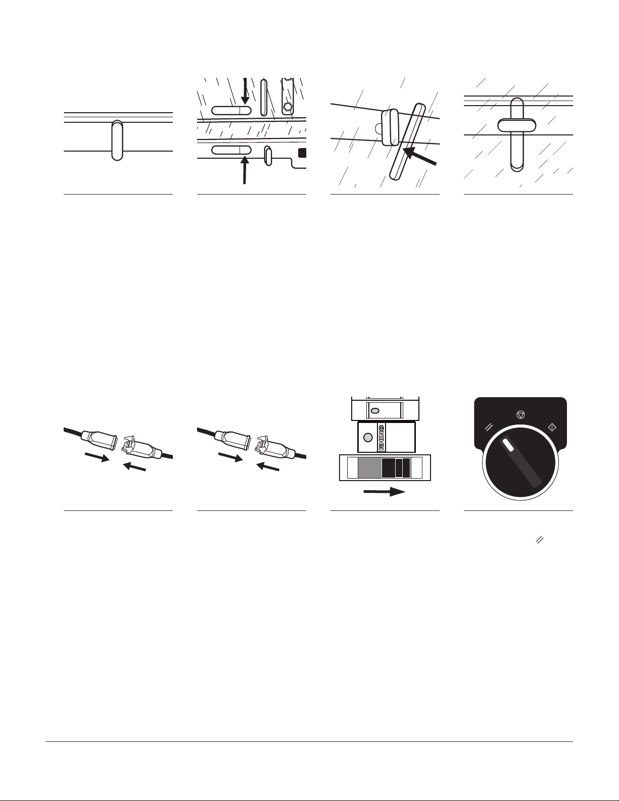
uInstall Conveyors In Tables / コンベアのテーブルへの設置
EN
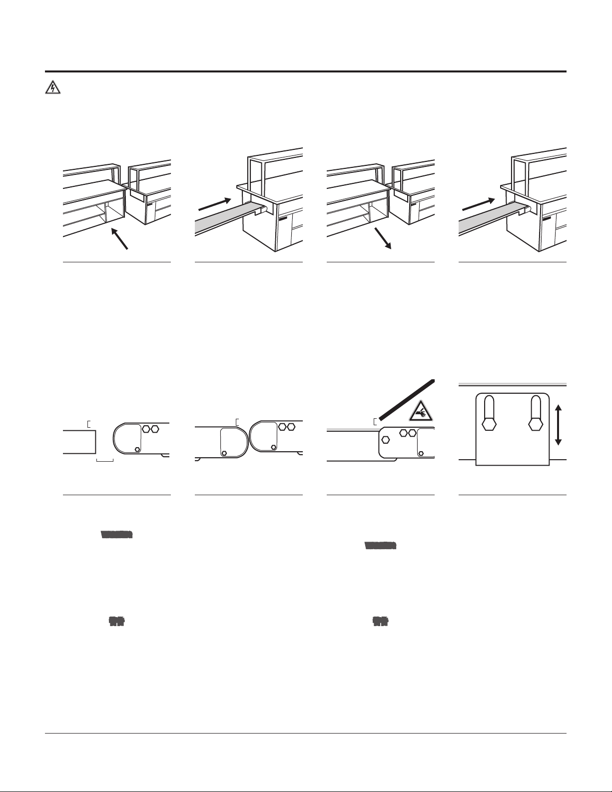
1Separate the tables so the
service cavity within the ECU
table is accessible.
2Slide the ECU conveyor, tail
first, into the ECU table. 3Move the tables back to-
gether to allow access to the
PREP tables service cavity.
4Slide the PREP conveyor, tail
first, into the PREP table.
JA テーブルを離してECUテーブルに
ある整備用開口部にアクセスで
きるようにします。
ECUコンベアをスライドさせて
テールからECUテーブルに挿入
します。
テーブルを元の位置に戻し
て、PREPテーブルの整備用開
口部にアクセスで きるようにし
ます。
PREPコンベアをスライドさせて
テールからPREPテーブルに挿
入します。
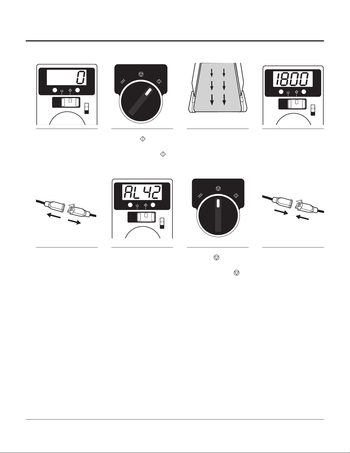
uCheck Conveyor Elevations / コンベアの高さ点検
3-5mm
25mm
OAT
3-5mm 3-5mm
EN
1Confirm the discharge end of
the ECU table conveyor is 3-5
mm above the OAT surface.
WARNING
Leave a 25 mm gap between the
conveyor and the OAT; a smaller
gap creates a pinch hazard.
2Confirm that the conveyors
transition point, at the end of
the PREP table, is 3-5 mm above
the ECU table. The conveyor bear-
ing housings should be between
0-5 mm apart at transition.
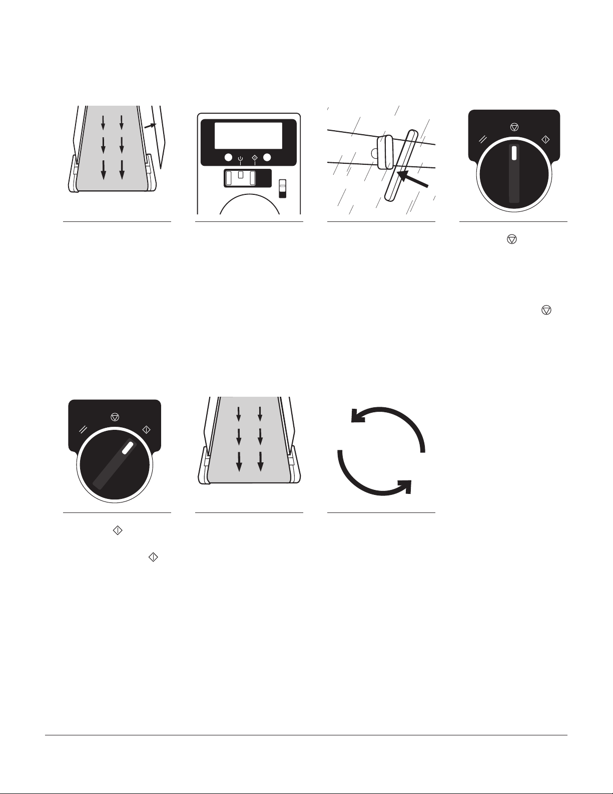
3Confirm that the top of the
PREP tables’ conveyor belt
is 3-5 mm below the bottom of
the chute.
WARNING
The chute and conveyor create
a pinch point; proper guarding
must be installed.
4Make adjustments as needed.
The mounting height can be
adjusted by loosening the hex head
screws with a 10 mm wrench.
JA ECUテーブルのコンベアの排出
側端部がOAT面よりも3~5 mm
高くなっていることを確認します。
警告
コンベアとOATの間には25 mm
の隙間を残してください。この隙
間が小さいと挟み込みによる事
故のおそれがあります。
コンベアの乗り換えポイントに
おいてPREPテーブルがECUテー
ブルよりも3~5 mm高くなって
いることを確認します。コンベア
のベアリングハウジングは乗り
換え部から0~5 mm離れるよう
にしてください。
PREPテーブルのコンベアベルト
がシュートの底部から3~5 mm
下にあることを確認します。
警告
シュートとコンベアの間は挟み
込みの可能性がある箇所です。
適切なガードを設置する必要が
あります。
必要に応じて調節を行います。
取り付け高さは六角ボルトを10
mmのスパナで緩めることで調
節可能です。

6PF Conveyors | Installation, Operation & Maintenance Manual
uInstall the Clear Plastic Guards / 透明プラスチックガードの設置
1
x4x4
1
EN
1Ensure that all twist nuts are
in the vertical position. 2Match the clear plastic guard
numbers with the correspond-
ing numbers on the conveyor
(4 clear plastic guards for each
conveyor).
3Install all 4 clear plastic
guards over the twist nuts
and onto the conveyor.
4Twist all of the nuts to the
horizontal, locked position.
JA すべてのツイストナットが縦位置
になっていることを確認します。
透明プラスチックガードの番号
が コンベアの番号に一致する
ようにします(各コンベアには
4個のプラスチックガードがあ
り ま す )。
4個の透明プラスチックガードす
べてを、ツイストナットを通して
コンベアに取り付けます。
すべてのナットを垂直になるよ
うにひねって、所定位置でロッ
クします。
Repeat this procedure for the second conveyor.
この手順を2台目のコンベアに繰り返します。
uConnecting Conveyors to Controllers / コンベアのコントローラへの接続
START
STOP
RESET
x2
EN
1Connect the ECU conveyor to
the control panel using the
ECU wire connector on the control.
2Connect the PREP conveyor
to the control panel using the
PREP wire connector on the control.
3Remove the plastic cover on
control, turn the circuit brea-
ker on, and remove the wire ties
from the face plates. Then replace
the plastic cover.
4Turn the control switch on
both the PREP and the ECU
tables to the <RESET> ( ) posi-
tion and release.
JA ECUコンベアを制御部のECUワ
イヤコネクタを使用して制御パ
ネルに接続します。
PREPコンベアを制御部のPREP
ワイヤコネクタを使用して制御
パネルに接続します。
制御部のプラスチックカバーを
取り外し、サーキットブレーカを
開いて、フェースプレートからワ
イヤタイを取り外します。次にプ
ラスチックカバーを元の位置に
配置します。
PREPおよびECUターブルの両方
で制御スイッチをオンにしてか
ら<RESET>( )位置にし、スイッ
チから手を放します。
Conveyors are now ready for commissioning.
これでコンベアの試運転の準備が整いました。

PF Conveyors | Installation, Operation & Maintenance Manual 7
Commissioning / 試運転
uChecking Controller / コントローラの点検
START
STOP
RESET
EN
1Verify the power to the control
panel and both controls
display “0”.
2Turn the control switch to
<START>
( )
.3Verify the conveyor belt is
moving towards the OAT /
front of the kitchen.
4The control will read 1800
(factory default) or the speed
to which it has been set.
JA 制御パネルおよび両方の制御部
への電力が「0」を示していること
を確認します。
制御スイッチを<START>( )
にします。
コンベアベルトがOAT(すなわち
キッチン前方に)向かって動いて
いることを確認します。
制御部には「1800」(工場初期設
定値)または設定した速度が表
示されます。
START
STOP
RESET
EN
5Create an error by discon-
necting the control cable
from the motor.
6Verify the control displays
AL42. 7Turn the control switch to
<STOP>
().
8Reconnect the control cable.
JA 制御ケーブルをモーターから切
り離してエラー状態を作ります。
制御部に「AL42」と表示されるこ
とを確認します。 制御スイッチを<STOP>( )に
します。
制御ケーブルをもとどおりにな
るように接続します。
Repeat this procedure for the second conveyor.
この手順を2台目のコンベアに繰り返します。
If the alarm condition does not clear, refer to the manufacturer’s manual for the control.
アラームの状態が不明な場合は、制御部に対して製造会社が作成した説明書を参照してください。

8PF Conveyors | Installation, Operation & Maintenance Manual
uChecking Controller (continued) / コントローラの点検(続き)
START
STOP
RESET START
STOP
RESET
EN
9Turn the control switch to
<RESET> ( ) to clear the
error.
10Verify the control displays
“0”. 11Turn the control switch to
<START> ( ). 12
Ensure the conveyor belt is
running.
JA 制御スイッチを<RESET>( )に
してエラーを解消します。
制御部に「0」と表示されることを
確認します。 制御スイッチを<START>( )
にします。
コンベアベルトが動いているこ
とを確認します。
If the conveyor does not start, the clear plastic guards may not be making contact with the sensors; or the emergency stop could be activated. Check all of the clear
plastic guards for proper placement and verify that all of the twist nuts are in the horizontal, locked position. Also, ensure the emergency stop is deactivated.
コンベアが始動しない場合、透明プラスチックガードがセンサーに接触していない、または緊急停止が作動している可能性があります。すべての
透明プラスチックガードが正しく配置されていること、およびすべてのツイストナットが水平のロックされた位置になっていることを確認します。
また緊急停止が作動解除になっていることも確認してください。
Repeat this procedure for the second conveyor.
この手順を2台目のコンベアに繰り返します。
If problems occur, please refer to the “Troubleshooting” section on page 24 of this manual for corrective actions.
問題が発生した場合、修正処置についてはこの説明書の24ページにある「トラブルシューティング」の項を参照してください。

PF Conveyors | Installation, Operation & Maintenance Manual 9
uTest Clear Plastic Guard Sensors / 透明プラスチックガードのセンサーの試験
Each clear plastic
guard
must be tested individually.
個々の透明プラスチックガードは、個別に試験される必要があります。
START
STOP
RESET
EN
1Remove a clear plastic guard
while the conveyor is running. 2Ensure the conveyor has
stopped and that the power
is off to the control panel. If the
power remains on or the conveyor
continues running, refer to the
“Troubleshooting“ section of this
manual on page 24.
3Replace the clear plastic
guard by sliding over the twist
nuts. Turn the nuts to the horizontal
position to lock in place.
4Turn the control switch to
<STOP>
().
JA コンベアの運転中に透明プラス
チックガードを取り外します。
コンベアは停止し、制御パネル
へ供給される電力はオフになる
ことを確認します。電力がオンの
ままであるか、コンベアが動き
続けている場合、この説明書の
24ページにある「トラブルシュ
ーティング」の項を参照してく
ださい。
透明プラスチックガードをツイス
トナットに沿ってずらすことで、
元の位置に配置します。ナットを
水平位置に回して所定位置でロ
ックしま す。
制御スイッチを<STOP>( )に
します。
START
STOP
RESET
EN
5Turn the control switch to
<START>
().
6Ensure the conveyor is
running. 7
Repeat these steps for
each clear plastic guard
on the conveyor.
JA 制御スイッチを<START>( )
にします。
コンベアが動いていることを確
認します。
これらの手順をコンベアの透明
プラスチックガードそれぞれに
対して繰り替えいます。
If the conveyor does not start, the clear plastic guards may not be making contact with the sensors; or the emergency stop could be activated. Check all of the clear
plastic guards for proper placement and verify that all twist nuts are in the horizontal, locked position. Also, ensure the emergency stop is deactivated.
コンベアが始動しない場合、透明プラスチックガードがセンサーに接触していない、または緊急停止が作動している可能性があります。すべての
透明プラスチックガードが正しく配置されていること、およびすべてのツイストナットが水平のロックされた位置になっていることを確認します。
また緊急停止が作動解除になっていることも確認してください。
Repeat this procedure for the second conveyor.
この手順を2台目のコンベアに繰り返します。
If problems occur, please refer to the “Troubleshooting” section on page 24 of this manual for corrective actions.
問題が発生した場合、修正処置についてはこの説明書の24ページにある「トラブルシューティング」の項を参照してください。

10 PF Conveyors | Installation, Operation & Maintenance Manual
uTest Transitions & Speed / 乗り換えおよび速度の試験
EN
1Start both conveyors and drop
a filled sandwich box into the
chute of the PREP table.
2Adjust the conveyor heights
as necessary for optimal
transitions.
3Adjust the conveyor speed,
faster or slower, until the
sandwich box lands in the optimal
spot on the OAT. (see the “Speed
Adjustment” section at the top of
page 13)
4Test the sandwich box several
times; checking the transi-
tions between the chute, conveyors,
and the OAT.
JA 両方のコンベアを始動し、PREP
テーブルのシュートに中身の入
ったサンドウィッチボックスを投
下します。
乗り換えがうまくいくように必要
に応じてコンベアの高さを調節
します。
コンベアの速度を速めたり、
遅くしたりして調節して、サンド
ウィッチボックスがOAT上の理
想的な位置に着地するようにし
ます。(13ページの上側にある「
速度の調節」の項を参照してく
ださい)
サンドウィッチボックスで数回
試験して、シュート、コンベアそ
してOATの間の乗り換えを確認
します。
If the test boxes hit the underside of the table, more adjustments may be needed to the conveyor height.
試験用のボックスがテーブルの下側にぶつかる場合、コンベアの高さをさらに調節しなければならない可能性があります。
uTest Emergency Stop / 緊急停止試験
EN
1While the conveyor is running,
press the emergency stop. 2Ensure that the conveyor
stops running. 3Reset the emergency stop
by twisting the button to the
depressed position.
JA コンベヤが動いている間に、緊
急停止ボタンを押します。
コンベアの動きが止まることを
確認します。
緊急停止ボタンをひねって、押
し下げられた位置にリセットし
ます。

PF Conveyors | Installation, Operation & Maintenance Manual 11
uComplete Commissioning / 試運転の完了
36 PF45 Conveyors | Installation, Operation & Maintenance Instructions
Service Record
Service Record / Service Record
Date Service Performed
uSerial Numbers
Prep Table Conveyor:
_________________________________
ECU Table Conveyor:
_________________________________
uDate of Installation
________________________________________________
PF45 Conveyors
Installation,Operation & Maintenance Instructions
QCIndustries,LLC
4057CloughWoods Dr.
Batavia,OH45103 USA
+1(513)753-6000
qcconveyors.com
Contents
Contents/ Contents
Warnings/Warnings / Warnings 2
Uncrating/Déballage / Auspacken 3
Installation/Installation / Installation 4
Operation/Operation / Operation 10
Controller/Controller / Controller 14
Tension&Tracking /Tension & Tracking /Tension & Tracking 15
Maintenance/Maintenance / Maintenance 17
MaintenanceChecklist/ Maintenance Checklist / Maintenance Checklist 24
ExplodedViews/ Exploded Views /ExplodedViews 26
ECDeclarationof Conformity 33
ECDeclarationof Conformity 34
ECDeclarationof Conformity 35
ServiceRecord / Service Record / Service Record 36
OriginalLanguage:English
TranslationsfromOriginal Language: French, German
EN
1If removed, replace the clear
plastic guard(s) by sliding
over the twist nuts at the cor-
responding number on the conveyor.
Turn the nuts to the horizontal
position to lock in place.
2Record the serial numbers
for the emergency panel and
all conveyors on the back cover of
this manual.
3File this manual in the store
office for future reference.
JA 透明プラスチックガードを取り外
していた場合は、コンベアの該
当する数字のところでツイストナ
ットに沿ってずらすことで、透明
プラスチックガードを元の位
置に配置します。ナットを水平
位置に回して所定位置でロック
します。
緊急停止パネルおよびすべての
コンベアのシリアル番号をこの
説明書の裏表紙に記録します。
将来参考資料として使用するた
めに、この説明書をストアオフィ
スで保管します。

12 PF Conveyors | Installation, Operation & Maintenance Manual
Operation / 操作
uStarting / 始動 uStopping / 停止
START
STOP
RESET START
STOP
RESET
EN
1Start the conveyor by turning
the control switch to <START>
().
1Stop the conveyor by turning
the control switch to <STOP>
().
JA 制御スイッチを<START>( )に
してコンベアを始動させます。
制御スイッチを<STOP>( )に
してコンベアを停止させます。
If the conveyor does not start, check that all of the clear plastic guards are in place and that the emergency stops are in the depressed position. If the conveyor still does
not start, refer to the “Troubleshooting” section of this manual on page 24.
コンベアが始動しない場合、すべての透明カバーが所定位置にあること、および緊急停止ボタンが押し下げられた位置にあることを確認します。依
然として始動しない場合は、この説明書の24ページにある「トラブルシューティング」の項を参照してください。
uResetting / リ セット
START
STOP
RESET START
STOP
RESET
EN
1If an alarm condition occurs,
the control must be reset. 2Turn the control switch to
<RESET> () and hold for
one second.
3If the control displays “0”,
the alarm has been cleared. 4Start the conveyor by turning
the control switch to <START>
().
JA アラームが出る場合、制御部をリ
セットする必要があります。 制御スイッチを<RESET>(
)にして1秒以上その状態を保
ちます。
制御部に「0」が表示されると、そ
のアラームは解除されています。 制御スイッチを<START>( )に
してコンベアを始動させます。
If the alarm condition does not clear, refer to the manufacturer’s manual for the controller.
アラームの状態が不明な場合は、コントローラ制御部に対して製造会社が作成した説明書を参照してください。

PF Conveyors | Installation, Operation & Maintenance Manual 13
uSpeed Change / 速度変更
The speed has been pre-programmed to 1800 rpm. This can be changed depending on operational needs once the conveyor is installed. If the control will not change speed, the
control may be locked. Refer to the “Unlocking Controller” procedure below.
速度は1800 rpmにあらかじめプログラミングされています。この値は、コンベア設置後に運用上の必要性に応じて変更することができます。制御部
によって速度の変更がされない場合、その制御部はロックがかけられています。以下の「コントローラのロック解除」を参照してください。
START
STOP
RESET START
STOP
RESET
EN
1Turn the control switch to
<STOP>
( )
and open the
plastic cover on the control panel
(do not disconnect).
2Rotate the dial on the control
until the desired speed is
displayed.
3Press the dial to set the
speed. 4Replace the plastic cover
on the control panel and
turn the control switch to <START>
( ).
JA 制御スイッチを<STOP>( )に
し、制御パネルのプラスチックカ
バーを開きます(外さないでく
だ さ い )。
制御ユニットのダイアルを回し
て、希望する速度を表示させ
ます。
ダイアルを押してその速度を設
定します。
プラスチックカバーを制御パネ
ルの所定位置に戻し、制御スイッ
チを<START>( )にします。
uUnlocking Controller / コントローラの ロック解 除
In normal operation the control should not be locked, but can become locked accidentally.
通常運転においては制御部はロックされないようになっていますが、不意にロックされる可能性もあります。
EN
1Press ‘mode’ once to reveal
“non” and allow the unlocking
procedure.
2Hold ‘mode’ for 5 seconds
and wait for the display to
flash “UnLK” and return to “non”.
3Press ‘function’ to return to
operating mode.
JA 「mode」を1回押すと「non」と
表示され、ロック解除手順を実
施できるようになります。
「mode」を5秒間押し続け、
表示が「UnLK」と点滅してから
「non」に戻るまで待ちます。
「function」を押して操作モード
に戻ります。

14 PF Conveyors | Installation, Operation & Maintenance Manual
uDaily Cleaning / 日次清掃作業
START
STOP
RESET
EN
1<STOP> the conveyor
().
2Remove the clear plastic
guards by twisting the nuts
to the vertical position and sliding
them off of the conveyor.
3Spray the rag with the diluted
cleaning solution. 4Wipe the visible portion of
the belt.
JA スイッチを<STOP>( )にして
コンベアを停止させます。
ナットを垂直位置までひねり、透
明プラスチックガ ード を ずらして
コンベアから取り外します。
希釈したクリーニング溶液をウェ
スに噴霧します。
ベルトの目で見える部分を拭
きます。
EN
5Pull the pins from both sides
of the conveyor’s tail. 6Lift the tail pulley. 7Manually advance the belt to
reveal the opposite side . 8Wipe the visible portion of
the belt.
JA コンベアのテールの両側面から
ピンを引き抜きます。
テールプーリーを持ち上げます。 ベルトを手で進めて反対側が見
えるようにします。
ベルトの目で見える部分を拭
きます。
4
EN
9Repeat steps 8 & 9 four
times until the entire belt
is clean.
10Spray the rag with the
diluted cleaning solution. 11Wipe the entire length of
the frame underneath the
conveyor belt.
12Wipe under the entire
length of the conveyor.
JA 手順8および9を4回繰り返し
て、ベルト全体から汚れを落と
します。
希釈したクリーニング溶液をウェ
スに噴霧します。
コンベアベルトの下になる部分
をフレームを全長にわたって拭
きます。
コンベアの下側を全長にわたっ
て拭きます。

PF Conveyors | Installation, Operation & Maintenance Manual 15
uDaily Cleaning (continued) / 日次清掃作業(続き)
EN
13Wipe under the tail pulley. 14Lower the tail pulley into
place. 15Replace both pins in the
conveyor’s tail pulley. 16Wipe both sides of each
clear plastic guard.
JA テールプーリーの下を拭きます。 テールプーリーを下げて所定位
置にします。
コンベアのテールプーリーに
2本のピンをもとどおり取り付
けます。
透明プラスチックガードの両面
を拭きます。
START
STOP
RESET
EN
17Replace the clear plastic
guards by sliding over
the twist nuts at the corresponding
numbers on the conveyor. Turn the
nuts to the horizontal position to
lock in place.
18<START> the conveyor
( ).
JA コンベアの該当する数字のとこ
ろでツイストナットに沿ってずら
すことで、透明プラスチックガー
ドを元の位置に配置します。ナッ
トを水平位置に回して所定位置
で ロックします。
スイッチを<START>( )にして
コンベアを始動させます。

16 PF Conveyors | Installation, Operation & Maintenance Manual
Maintenance /整備
uBeginning Maintenance / 整備のための準備
The following steps must be completed before performing any of the maintenance procedures described in the “Maintenance” section.
「整備」の項に記述されているどの整備手順であっても、その実施の前に次の手順を完了させておく必要がありま す。
Ensure the power to the conveyor is disengaged by turning the control switch on the control panel to the <OFF> position.
制御パネルの制御スイッチを<OFF>位置にすることで、コンベアへの電力供給が遮断されていることを確認します。
Verify the power is shut off and locked out.
電力が切られており、ロックされていることを確認します。
EN
1Disconnect the conveyor from
the control panel. 2Remove the clear plastic
guards by twisting the nuts to
the vertical position and sliding off
of the conveyor.
3Remove from table.
Weight: 70 lbs
(32 kg); lift with
two people.
4Relieve tension on the belt
by removing both pins from
the tail and rotate the tail up to the
disengaged position.
JA コンベアを制御パネルから遮断
してください。
ナットを垂直位置までひねり、透
明プラスチックガ ード を ずらして
コンベアから取り外します。
テーブルから取り外します。
重量:32 kg
(70 lb)、
2名で持ち上げてください。
テールから2本のピンを取り外し
てベルトの張力を緩め、テールを
回して分離位置にします。
uBelt Change / ベルトの交換
EN
1Place the conveyor on its side
with the motor down. 2Slide the old belt off of the
conveyor frame. 3Slide the new belt over the
drive pulley. 4Slide the new belt over the
tail pulley.
JA コンベアをモーターの付いてい
る側が下になるように置きます。
古いベルトをスライドさせてコン
ベアフレームから外します。
新しいベルトをドライブプーリー
の上にスライドさせます。
新しいベルトをテールプーリー
の上にスライドさせます。
To complete the belt change, refer to the “Finalizing Maintenance” section on page 22 of this manual.
ベルトの交換作業を完了させるために、この説明書の22ページにある「最終整備」の項を参照してください。

PF Conveyors | Installation, Operation & Maintenance Manual 17
uBelt Tensioning / ベルトの張力調節
If the belt slips or is stopping, improper tension may be the cause. See steps below for corrective actions.
ベルトがスリップしたり停止する場合、張力調整が不正であることが原因である可能性があります。修正措置については以下を参照してください。
EN
1Loosen the upper hex head
screw on the tension window
cover.
2Rotate the tension window
cover to the open position. 3Rotate the hex head cap
screw to add or remove
tension on that side of the conveyor
with a 10 mm box head wrench.
4Repeat the process on the
opposite side of the conveyor
using the exact same number of
rotations as step 3.
JA テンションウィンドウカバーにあ
る上側の六角ねじを緩めます。
テンションウィンドウカバーを回
して開位置にします。
10 mmのボックスヘッドレンチ
を使用して、その六角穴付きね
じを回すことで、コンベアの該当
する側の張力を増減します。
この手順をコンベアの反対側に
対して手順3と全く同じ回転数を
用いて繰り返します。
EN
5Repeat this process until
proper tension is achieved. 6Rotate the tension window
cover into place. 7Tighten the upper hex head
screw on the tension window
cover.
8Repeat steps 6 & 7 on the
opposite side of the conveyor
to ensure both tension window cov-
ers are closed.
JA 適正な張力が得られるまでこの
手順を繰り返します。
テンションウィンドウカバーを回
して所定位置にします。
テンションウィンドウカバーに
ある上側の六角ねじを締め付
けます。
手順6および7をコンベアの反対
側に対して繰り返して、両方のテ
ンションウィンドウカバーを確実
に閉めます。
Replace the sides and check the tracking if necessary. Refer to the “Belt Tracking” section on pages 18 &19 of this manual.
必要に応じて、側面を交代したうえで、軌道を点検します。この説明書の18および19ページの「ベルトの軌道調節」の項を参照してください。

18 PF Conveyors | Installation, Operation & Maintenance Manual
uBelt Tracking / ベルトの軌道調節
Tracking requires access to both sides of the conveyor. It is necessary to remove the conveyor from the table to properly track the belt.
軌道調節するためにはコンベアの両側にアクセスする必要があります。ベルトを適正に軌道調節するにはテーブルからコンベアを取り外す必要があります。
If the belt is squeaking or riding too far to one side of the conveyor, improper tacking may be the cause. See the steps below for corrective actions.
ベルトから音鳴りがする場合やコンベアの片方から異常に遠ざかる場合、軌道調節が不正であることが原因である可能性があります。修正措置については以下を参
照してください。
START
STOP
RESET
EN
1Replace the clear plastic
guards by sliding them over
the twist nuts at the corresponding
numbers on the conveyor. Turn the
nuts to the horizontal position to
lock in place.
2Reconnect the conveyor to
the control panel. 3Run the conveyor by turn-
ing the
control
switch to
<START>
( )
and make observa-
tions. A belt is mistracked when it
rides closer to one side or there is
bulging at the center of the belt.
4To start tracking the belt,
<STOP>
()
the conveyor.
JA コンベアの該当する数字のとこ
ろでツイストナットに沿ってずら
すことで、透明プラスチックガー
ドを元の位置に配置します。ナッ
トを水平位置に回して所定位置
で ロックします。
コンベアを制御パネルに、もとの
とおりに接続します。
制御スイッチを<START>にして
コンベアを始動させ、観察を実
施します。ベルトが片側に寄りす
ぎている場合や、ベルトの央に
ふくらみがある場合、ベルトの軌
道が不正になります。
ベルトの軌道調節をするには、ス
イッチを<STOP>( )にしてコ
ンベアを停止させます。
EN
5Remove the clear plastic
guards by twisting the nuts to
the vertical position and sliding off
of the conveyor.
6Loosen the upper hex head
screw on the tension window
cover and rotate up.
7Add or remove tension to one
side of the belt by turning
the tensioning screw a 1/4 turn
at a time.
8The belt will move away from
the side with the greatest
tension.
JA ナットを垂直位置までひねり、透
明プラスチックガ ード を ずらして
コンベアから取り外します。
テンションウィンドウカバーにあ
る上側の六角ねじを緩め、テンシ
ョンウィンドウカバーを上になる
ように回します。
張力調節ねじを1度につき1/4回
転回して、ベルトの片側の張力
を増減します。
張力を最大にすると、ベルトは
端から遠ざかります。

PF Conveyors | Installation, Operation & Maintenance Manual 19
uBelt Tracking (continued) / ベルトの軌道調節(続き)
START
STOP
RESET
EN
9Replace the clear plastic
guards by sliding over the
twist nuts at the corresponding
numbers on the conveyor. Turn the
nuts to the horizontal position to
lock in place.
10<START> the conveyor
( ).
11Correct tracking is
achieved when some of
the tail pulley is visible on both
sides of the belt.
12Repeat this process
until proper tracking is
achieved.
JA コンベアの該当する数字のとこ
ろでツイストナットに沿ってずら
すことで、透明プラスチックガー
ドを元の位置に配置します。ナッ
トを水平位置に回して所定位置
で ロックします。
スイッチを<START>( )にして
コンベアを始動させます。
テールプーリーの一部がベルト
の両側で目視できる場合に、正
しい軌道調節が得られます。
適正な軌道が得られるまでこの
手順を繰り返します。
EN
13Once proper tracking
is achieved, ensure the
conveyor is stopped and rotate the
tension window cover into place.
14Tighten the upper hex
head screw on the ten-
sion window cover.
JA 適切な軌道調節が得られたらコ
ンベアを確実に停止させ、テン
ションウィンドウカバーを回して
所定位置にします。
テンションウィンドウカバーに
ある上側の六角ねじを締め付
けます。

20 PF Conveyors | Installation, Operation & Maintenance Manual
uGearmotor Change / ギアモーターの交換
x2
x4x4
EN
1Use an 8 mm socket to
loosen and remove the two
hex clamping screws that hold the
drive pulley to the gearmotor.
2With a 13 mm wrench, loosen
and remove the four hex head
bolts holding the gearmotor to the
mounting plate.
3Slide the gearmotor out
of the drive pulley and the
mounting plate.
4Apply anti-seize to the motors
shaft and slide through the
motor mounting bracket into the
pulley.
JA 8 mmのソケットを使用して、ド
ライブプーリーをギアモーター
に保持している2本の六角固定
ネジを緩めて取り外します。
13 mmのスパナを使用してギア
モーターを取付プレートに保持
している4本の六角ボルト緩め
て取り外します。
ギアモーターをスライドさせてド
ライブプーリーおよび取付プレー
トから外します。
アンチシーズ剤をモーターシャ
フトに 塗 布し、モ ー ターシャフト
をモーターの取付ブラケットに
沿って滑らせてプーリーに挿入
します。
x4x4
24mm
EN
5Apply removable threadlo-
cker to the motor mounting
screws.
6Insert and tighten the four
motor mounting screws with a
13 mm wrench.
7Ensure the gap between the
motor and the pulley is 24
mm.
8Apply removable thread-
locker to the pulley clamping
screws.
JA 除去可能なねじロック剤をモー
ターの取付ねじに塗布します。
4本のモーター取付ねじを挿入
し、13 mmのスパナを使用して
締め付けます。
モーターとプーリーの間隔が24
mmになるようにします。
除去可能なねじロック剤をプー
リー保持ねじに塗布します。
x2
EN
9Insert and tighten both of the
pulley clamping screws using
an 8 mm socket.
10Dispose of the gearmotor
in compliance with WEEE
or return to QC Conveyors for
disposal.
JA 2本のプーリー保持ねじを挿入
し、8 mmのソケットで締め付
けます。
WEEEに従ってギアモータを廃
棄するか、廃棄のためにQCコン
ベアまで返却します。
Other manuals for QC CONVEYORS PF52
2
Table of contents
Other DURAVANT Accessories manuals

DURAVANT
DURAVANT QC Conveyors AS40 Owner's manual

DURAVANT
DURAVANT FMH BestReach User manual

DURAVANT
DURAVANT QC CONVEYORS PF52 User manual

DURAVANT
DURAVANT QC Conveyors PF51 Instruction Manual

DURAVANT
DURAVANT QC Conveyors PF22 Guide

DURAVANT
DURAVANT FMH NestaFlex Gravity 376PL User manual

DURAVANT
DURAVANT QC CONVEYORS PF52 Instruction manual