DuraVent DuraTech Canada User manual

1
NOTE: DIAGRAMS & ILLUSTRATIONS ARE NOT TO SCALE.
DuraTech®Canada DTC
Factory-built CHIMNEY
5”, 6”, 7”, 8” & 10” dia.
TYPE HT
INSTALLATION
AND
OPERATION
INSTRUCTIONS
Read these instructions and keep them for future reference
These instructions must be followed in all details. Failure to do so may result in a hazardous installation.
Listed: Warnock Hersey 9651
Standard: CAN / ULC-S604
UL-103HT
CAN / ULC-S629
(6’’, 7’’, 8’’ only)
CONTENTS
RECOMMENDATIONS
& APPLICATIONS…………......2
MAINTENANCE AND SIZING
CHART……………………….3
GENERAL INSTALLATION
NOTES…................................4-5
INTERIOR STRAIGHT
INSTALLATION
-SINGLE FLOOR……………6-7
INTERIOR STRAIGHT
INSTALLATION -MULTIPLE
FLOOR………………...........8-9
INTERIOR INSTALLATION
WITH CATHEDRAL
CEILING……….…............10-12
OFFSET
DEVIATION…………….....13-14
WARNING
A MAJOR CAUSE OF CHIMNEY-RELATED
FIRES IS FAILURE TO MAINTAIN REQUIRED
CLEARANCES (AIR SPACES) TO COM-
BUSTIBLE MATERIALS. IT IS OF UTMOST
IMPORTANCE THAT THIS CHIMNEY BE
INSTALLED ONLY IN ACCORDANCE WITH
THESE INSTRUCTIONS.
EXTERIOR INSTALLATION…….15-19
INTERIOR INSTALLATION ON A
FURNACE, BOILER, OR WATER
HEATER…..................................20-21
SPECIALIZED COMPONENTS……..22
REPLACEMENT PARTS..............23-25
WARRANTY……………………...27
877 Cotting Court, Vacaville, CA 95688
800-835-4429; www.DuraVent.com
PIDURATECHCANADA L874 REV. 5 01/22/2021

2NOTE: DIAGRAMS & ILLUSTRATIONS ARE NOT TO SCALE.
APPLICATIONS
The DTC chimney has been designed for use with
wood, gas, oil, and coal in residential, commercial
and industrial applications, specially developed for
use with controlled-combustion stoves and wood
burning replace .
In the USA, DTC is listed to UL-103HT, 2100°F in
diameters of 5, 6, 7, 8 and 10 inches.
In Canada, DTC is listed to ULC-S629, 2100° F in
diameters 6, 7, and 8 inches for wood/coal application.
In Canada, DTC is also designed for use with gas or
oil red heating appliances such as furnaces, water
heaters, and other appliances, as per ULC-S604 in
diameter 5 to 10 inches.
If you are planning to install a wood stove, we rec-
ommend that you:
1. Choose the right size stove. Do not buy one larger
than you need.
2. Connect only one appliance to a chimney.
3. Never overre your stove. If any part of the stove or
stove pipe is glowing red, then you are overring.
Immediately close the stove’s dampers until the
system cools. The high temperature caused by
overring can permanently damage the stove and
stove pipe and may overheat nearby combustible
walls and furniture.
WOOD AND COAL STOVES
RECOMMENDATIONS
Clearance
The clearances stated in this guide are minimum re-
quirements: if more space is available, use it. Min-
imum clearances mean leaving unobstructed air
space. Do not ll these spaces with any material
whatsoever, especially not home insulating material
except specied otherwise. If you insulate your attic
later, be sure to maintain the necessary clearance.
Inspection
Contact local building or re ocials about restric-
tions, installation inspections and permits that may
be required in your area.
Replacement Parts
If a component of your chimney system is damaged
it must be replaced by an identical one from
DuraVent.
4. Install the stove and stove pipe as described in the
installation instructions accompanying the stove.
Be certain to maintain the required clearances to
combustible construction.
5. Keep your ue gases between 300°F and 500°F.
This will maximize eciency while minimizing con-
densation and creosote formation. Do not ll your
stove with wood and allow it to smolder for 8 to
10 hours. This condition produces large amounts
of creosote in the chimney.
6. Do not burn sea driftwood or treated wood. These
combustibles are highly corrosive to all types of
stainless steel.
FACTORY BUILT FIREPLACES
DTC is suitable for use with closed or opened re-
places certied for use with the DTC.
When doing so please refer to the replace installation
instruction to install the chimney.

3
NOTE: DIAGRAMS & ILLUSTRATIONS ARE NOT TO SCALE.
CREOSOTE - FORMATION AND NEED
FOR REMOVAL
NOTE: ALL DIMENSIONS ARE IN INCHES.
Wood stoves can quickly create large deposits of
creosote in the chimney. Some wood stoves can
create enough creosote in two weeks to cause a
chimney re.
When wood is burned slowly, it produces tar and other
organic vapours, which combine with expelled mois-
ture to form creosote. The creosote vapours condense
in the relatively cool chimney ue of a slow-burning
re. As a result, creosote residue accumulates on
the ue lining. When ignited this creosote makes an
extremely hot re.
When using a wood stove, we recommend that you::
1. Initially, inspect the chimney system weekly. You
will learn how often it will be necessary to clean
your chimney.
2. The chimney should be inspected at least once every
2 months during the heating season to determine
if a creosote or soot build-up has occurred: if a
signicant layer of creosote has accumulated (3
mm or 1/8’’), it should be removed to reduce the
risk of chimney re.
3. Have your chimney cleaned by a qualied chimney
sweep. If you want to clean your chimney yourself:
clean your chimney using plastic or stainless steel
brushes. Do not use a brush that will scratch the
stainless steel interior of your chimney.
4. Do not expect chemical chimney cleaners to keep
your chimney clean. Their use does not negate the
necessity of periodically inspecting and cleaning
your chimney.
CAP REMOVAL FOR MAINTENANCE
To remove cap, unscrew the collar screw to un-
tighten the collar.
Pull on the cap to remove it from the chimney.
To put the cap back in place, slide it over the
chimney and then tighten the collar using the col-
lar screw.
SIZING CHART
CHIMNEY-SIZE 5” 6” 7” 8” 10”
OUTSIDE-DIAMETER 7” 8” 9” 10” 12”
FRAMING DIMENSION REQUIRED
Reduced Clear. Support
(RCS) -- 10 1/8” 11 1/8” 12 1/8” --
Square support (CS24) -- 12-1/8” 14-3/8” 14-3/8” 14-3/8”
Wall Thimble (WTI) 11-3/8” 12-3/8” 13-3/8” 14-3/8” 16-3/8”
Finish support (FSC) -- 12-1/8” 14-3/8” 14-3/8” --
Firestop (FS) 11-3/8” 12-3/8” 13-3/8” 14-3/8” 16-3/8”
Attic Radiation Shield
(ISIA) 11-3/8” 12-3/8” 13-3/8” 14-3/8” 16-3/8”
MAX. LENGTH HEIGHT SUPPORTED **
Tee Support (TS) 63’ 63’ 55’ 48’ 39’
Roof Support (RS) 42’ 34’ 27’ 24’ 20’
Square Support (CS24) -- 60’ 50’ 45’ 35’
Reduced Clearance
Support (RCS) -- 60’ 50’ 45’ --
Finish Support (FSC) -- 75’ 65’ 59’ --
Offset/WallSupport (RESU)
-- 28’ 24’ 20’ 14’
Insulated Tee (TSS) * 63’ 63’ 55’ 50’ 50’
Clearance To
Combustibles 2” 2” 2” 2” 2”
* When installed on a concrete footing.
** NOTE: If greater height is required, use additional roof supports at
intervals not exceeding 30’
Table 1
WARNING
In Case of Fire: If a ue re occurs, close all appliance
dampers and source of combustion air, and call your
Fire Department. Do not use the chimney again, until it
has been inspected for possible damage.

4NOTE: DIAGRAMS & ILLUSTRATIONS ARE NOT TO SCALE.
GENERAL INSTALLATION NOTES
INSTALLATION NOTES
1
1. The chimney is intended for use with solid, liquid,
and gaseous fuel burning appliances. In Canada,
only 6”, 7” and 8” dia. for solid fuel.
Allowable ue gas temperature:
Maximum continuous 1200° F (650°C)
Brief forced ring 1400°F (760°C)
Tested to 2100°F (1150°C) - 30 minutes
2. The maximum height of chimney supported by the
various DuraVent supports are outlined on Table 1.
3. The supports described in this manual should only
be used with DuraVent’s model DTC, 5”, 6”, 7”, 8”
and 10” factory built chimneys.
4. Size the chimney in accordance with the appliance
manufacturer’s instructions.
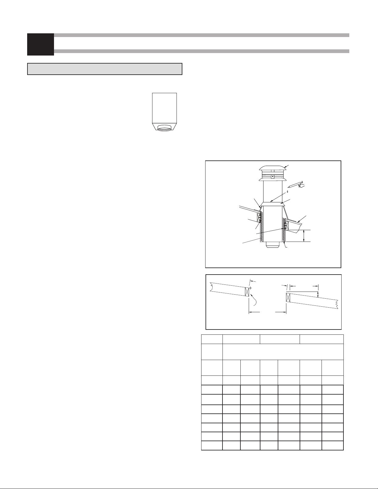
5. When a restop is required, it is important to follow the
framing dimensions for oor openings as prescribed
in this manual. see Table 2).
6. A chimney servicing a replace or an incinerator shall
not serve any other appliance.
7. The chimney shall extend at least 3 ft above its point
of contact with the roof and at least 2ft higher than
any wall, roof or adjacent building within 10 ft of it.
8. The maximum height of an unguided chimney above
the roof is 5 ft. If the chimney extends more than 5 ft.
above the roof, a Universal Roof Brace (XRB) must
be used.
9. The clearance between single wall pipe and unpro-
tected combustible material must not be less than 18”
(see National Building Code and NFPA 211) except:
The distance between the vertical stove pipe and the
ceiling may be less than 18” and will be established
by the nish support.
10. Multi-Story: Consult local building codes for re-
quirements in your area. In the U.S., the National
Fire Protection Association Standard #211 states:
“Factory-built chimneys that pass through oors of
buildings requiring the protection of vertical openings
shall be enclosed with approved walls having a re
resistance rating of not less than one hour when
such chimneys are located in a building less than
4 stories in height, and not less than 2 hours when
such chimneys are located in a building more than 4
stories in height.” In Canada, except in single-family
HOLE SIZE
DOWN
B
ROOF SLOPE
INCHES
SIDES OF HOLE
MUST
BE VERTICAL
12 IN
X
ACROSS
SLOPE
A
Figure 1
CHIMNEY SIZE 5” 6” 7”
ROOF SLOPE ROOF HOLE SIZE
x/12 A B A B A B
011-3/8 11-3/8 12-3/8 12-3/8 13-3/8 13-3/8
2/12 11-3/8 11-1/2 12-3/8 12-1/2 13-3/8 13-1/2
4/12 11-3/8 12 12-3/8 13 13-3/8 14-3/32
6/12 11-3/8 12-11/16 12-3/8 13-13/16 13-3/8 14-15/16
8/12 11-3/8 13-11/16 12-3/8 14-7/8 13-3/8 16-1/16
10/12 11-3/8 14-13/16 12-3/8 16-1/8 13-3/8 17-7/16
12/12 11-3/8 16-1/16 12-3/8 17-1/2 13-3/8 18-29/32
ROOF OPENING CHART
CHIMNEY SIZE 8” 10”
ROOF SLOPE ROOF HOLE SIZE
x/12 A B A B
014-3/8 14-3/8 16-3/8 16-3/8
2/12 14-3/8 14-9/16 16-3/8 16-19/32
4/12 14-3/8 15-5/32 16-3/8 17-1/4
6/12 14-3/8 16-3/32 16-3/8 18-5/16
8/12 14-3/8 17-1/4 16-3/8 19-11/16
10/12 14-3/8 18-23/32 16-3/8 21-5/16
12/12 14-3/8 20-11/32 16-3/8 23-5/32
Table 2 - Refer to Figure 1

5
NOTE: DIAGRAMS & ILLUSTRATIONS ARE NOT TO SCALE.
WARNING
The clearance between the chimney and combustible
material must not be less than 2", except where
established by the support. Do not ll this area with
insulation unless directed otherwise in these
instructions.
GENERAL INSTALLATION NOTES (CONT’D)
1
and two-family dwellings, chimneys which extend
through another story must have an enclosure with a
re resistance rating equal to or greater than that of
the oor or roof assembly through which they pass.
11. Do not ll the 2” space around the chimney with
household insulation or any other material unless
specied otherwise. Insulation placed in this area
could cause adjacent combustibles to overheat.
12. Self-tapping stainless screws are not required, but
may be used to reinforce the connection and avoid
accidental unlocking of chimney lengths. Use only
1/2” self-tapping screws. Do not penetrate the inner
wall of the chimney.
13. When penetrating an exterior wall or ceiling/roof
assembly, the vapor barrier must be repaired. This
is easily accomplished by attaching the vapor barrier
to the outer perimeter of any wall thimble, Firestop,
or ceiling support component using approved
sealant or tape, while also maintaining the minimum
clearances-to-combustibles to the chimney’s outer
wall. When penetrating the building envelope, the
gap between the outer layer of chimney and any
Firestop or wall thimble can be sealed using high-
temperature rated (316°C / 600°F) silicone caulking.
Should you require further clarication, consult your
local authority having jurisdiction.
13. The safe operation of a factory-built chimney as-
sembly is based on the use of parts supplied by the
manufacturer and the performance of the assembly
may be aected if the combination of these parts is
not used in actual building construction.
Acceptance of the assembly is void if the installation
instructions are not followed.
15. Provisions must be made to ensure that all interior
portions of the chimney be accessible for inspection
and cleaning.
2 ft
MIN.
10 ft
3 ft
MIN.
ROOF RADIATION
SHIELDS (US only)
ATTIC
RADIATION
SHIELD
2" MIN.
FIRESTOP
ENCLOSURE
2" MIN.
7 1/2"
MIN.
BASE TEE
* 18"
MINIMUM
* 18"
MINIMUM
* CLEARANCE CAN BE REDUCED IF A LISTED CHIMNEY CONNECTOR
IS USED.
** CLEARANCES CAN BE LESS THAN 2" WHERE ESTABLISHED BY THE
SUPPORT. Figure 2
SUPPORT

6NOTE: DIAGRAMS & ILLUSTRATIONS ARE NOT TO SCALE.
INTERIOR STRAIGHT INSTALLATION - SINGLE FLOOR
2
FRAMING DIMENSION
CHIMNEY
SIZE
Reduce Clearance
Support
ROOF
6" 10-1/8’’ x 10-1/8’’ 12-3/8’’ x 12-3/8’’
7" 11-1/8’’ x 11-1/8’’ 13-3/8’’ x 13-3/8’’
8” 12-1/8” x 12-1/8” 14-3/8” x 14-3/8”
Table 3
Figure 3
NAILS OR SCEW
Reduced Clearance
Support (RCS)
When using the Reduced Clearance Support (RCS) at
the attic level, the use of the attic radiation shield
is not required. The Reduced Clearance Support
(RCS) acts as an attic radiation shield when
installed with insulation and a collar (provided)
(see gure 3).
NOTE: A Finishing Support (FSC) combined with an Attic
Radiation Shield (ISIA) can also be used for this
application. Refer to page 8 for installation guide.
Step 1: Locate the chimney in a convenient place as
near as possible to the appliance outlet.
Step 2: Cut and frame the opening in the ceiling and
roof where the chimney will pass.
NOTE: It is important to follow the cutting dimensions
for oor openings as prescribed in this manual.
Step 3: From below, push the Reduced Clearance
Support into the framed opening in the ceiling.
Ensuring the support is level, attach the support
to the framed opening using (12) - 3” spiral
nails or #8 x 1 1/2” wood screws (see Figure 3).
NOTE: At least 3 1/2” of the support must extend
down below the nished ceiling. This ensures
minimum clearances are maintained to
stovepipe. Fix the Finish Trim around the support
using supplied screws. Figure 4
RAIN CAP
STORM COLLAR
FLASHING
COLLAR
FINISH TRIM
INSULATION
"ROCKWOOL"
2" CLEARANCE
TO ROOF FRAMING
CHIMNEY TO CEILING FRAMINGG
33 11
22minmin
Reduced Clear.
Support (RCS)
(Included w/ RCS)
(Included w/ RCS)
ROOF RADIATION
PLATE (USA only)
S

7
NOTE: DIAGRAMS & ILLUSTRATIONS ARE NOT TO SCALE.
SILICONE
CAULKING
Figure 5
Step 4: Place rst chimney length into the support.
Twist to lock into place. Wrap the insulation
pad around the chimney section removing any
excess. Slide insulation pad into the space
between the chimney section and support
making sure the insulation makes contact with
the bottom of the support. Additional pieces of
insulation can be loosely tucked down within
corners. Do not compress insulation. This
reduces eectiveness.
NOTE: If needed a Support Extension (SE) can be
attached to the support to increase its height.
See page 11.
NOTE: Make sure arrow on pipe label is pointing upward.
Step 5: Place the Square-to-Round Collar, included
with the ceiling support, around the chimney
on top of the square support. Make sure it
completely covers the top of the square support.
Step 6: Stack the next chimney length on the rst
length. Be sure that the male and female threads
are not in line when putting the lengths together.
Turn the chimney clockwise to lock it in place.
Continue until the required chimney height is
reached.
Step 7: (USA ONLY) - ROOF RADIATION SHIELD
Install the Roof Radiation Shield in the roof joists.
This shield consists of (4) metal plates supplied
with the Roof Flashing. Nail one plate to each
side of the joists using (2) - 2 1/2” nails.
Step 8: ROOF FLASHING INSTALLATION
Put the roof ashing in place. Seal the joint
between the roof and the ashing with roong
compound.
For sloping roofs, place the ashing under the
upper shingles and on top of the lower shingles.
Nail the ashing to the roof using nails. Place
the storm collar around the chimney and slide
down on top of the ashing.
INTERIOR STRAIGHT INSTALLATION - SINGLE FLOOR (CONT’D)
2
Step 9: Tighten the collar using the supplied bolt.
Make sure the joint is properly caulked (see
Figure 5).
Step 10: Attach the rain cap to the top of the chimney.

8NOTE: DIAGRAMS & ILLUSTRATIONS ARE NOT TO SCALE.
INTERIOR STRAIGHT INSTALLATION - MULTIPLE FLOOR
3
Step 1. Locate the chimney in a convenient place as
near as possible to the appliance outlet.
Step 2. Cut and frame the openings in the oor, ceiling
and roof where the chimney will pass.
NOTE: It is important to follow the framing dimensions
for the oor openings prescribed in this manual.
HOLE SIZE
CHIMNEY
SIZE
FINISH SUPPORT
(FSC)
RADIATION SHIELD
& ROOF
*
5" 12-1/8" x 12-1/8" 11-3/8" x 11-3/8"
6" 12-1/8" x 12-1/8" 12-3/8’’ x 12-3/8’’
7" 14-3/8" x 14-3/8" 13-3/8’’ x 13-3/8’’
8" 14-3/8" x 14-3/8" 14-3/8’’ x 14-3/8’’
10" --- 16-3/8’’ x 16-3/8’’
Table 4
* For sloping roofs see size Table 2 on page 3
Step 3. From below push the nish support into
the framed opening. Nail or screw the sup-
port to the framed box using (12) 3" spiral
nails or #8 x 1 1/2” wood screws
(see Figure 6).
FINISH SUPPORT (FSC)
NAILS
Figure 6
7
6
5
4
3
2
1
1. BLACK STOVE PIPE
2. FINISHING SUPPORT
3. INSULATED LENGTH
4. FIRESTOP
5. ATTIC RADIATION SHIELD
6. ADJUSTABLE ROOF FLASHING
7. RAIN CAP
Figure 7
IF USING THE REDUCED CLEARANCE SUPPORT
(RCS), REFER TO PAGE 6 FOR DIMENSION AND
COLLAR CAN BE DISCARDED.

9
NOTE: DIAGRAMS & ILLUSTRATIONS ARE NOT TO SCALE.
SCREWS
SCREWS
(ISIA)
FIRESTOP
(FS)
SCREWS
SILICONE
CAULKING
Figure 8 Figure 9
INTERIOR STRAIGHT INSTALLATION - MULTIPLE FLOOR (CONT’D)
3
Step 4. Put this rst chimney length in the support.
Turn it clockwise to lock it in place (see Fig-
ure 7).
NOTE: Arrow on pipe label must be pointing up.
Step 5. From below, install a Firestop (FS) in each
oor through which the chimney passes.
Step 6. Stack the next chimney length on the rst
length. Be sure that the male and female
threads are not in line when putting the
lengths together. Turn the chimney clock-
wise to lock it in place. You may add a 1/2”
stainless steel self tapping screw to prevent
accidental unlocking. Continue until the re-
quired chimney height is reached.
Step 7. At the attic level, install a Firestop (FS),
from below and an Attic Radiation Shield
(ISIA) and Storm Collar from above (see Fig-
ure 8).
(USA ONLY) Install the Roof Radiation Shield
in the roof joists. This shield consists of four
metal plates supplied with the roof ashing.
Nail one plate to each side of the joist using
(2) - 2 1/2’’ nails.
Step 8. ROOF FLASHING INSTALLATION
Put the roof ashing in place. Seal the joint
between the roof and the ashing with roof-
ing compound.
For sloping roofs, place the ashing under
the upper shingles and on top of the lower
shingles. Nail the ashing to the roof using
roong nails.
Place the storm collar over the chimney and
the ashing. Tighten it with the bolt supplied
making sure the joint is properly caulked (see
Figure 9).
Step 9. Attach the rain cap to the top of the
chimney.
ATTIC RADIATION

10 NOTE: DIAGRAMS & ILLUSTRATIONS ARE NOT TO SCALE.
RCS
HOLE SIZE
DOWN
B
ROOF SLOPE
INCHES
SIDES OF HOLE MUST
BE VERTICAL
12 IN
ACROSS
SLOPE
A
Figure 11
Table5
6” 7” 8”
Chimney
Size Hole Size (Reduce Clearance Support)
Roof
Slope A B A B A B
x/12
010-1/8 10-1/8 11-1/8 11-1/8 12-1/8 12-1/8
2/12 10-1/8 10-1/4 11-1/8 11-1/4 12-1/8 12-1/4
4/12 10-1/8 10-5/8 11-1/8 11-3/4 12-1/8 12-3/4
6/12 10-1/8 11-1/4 11-1/8 12-1/2 12-1/8 13-1/2
8/12 10-1/8 12-1/8 11-1/8 13-1/4 12-1/8 14-1/2
10/12 10-1/8 13-1/4 11-1/8 14-1/2 12-1/8 15-7/8
12/12 10-1/8 14-1/4 11-1/8 15-3/4 12-1/8 17-1/8
X
NOTE: The Reduced Clearance Support (RCS)
comes with a collar. It can be discard-
ed for a Cathedral Ceiling application, it
is not required.
Step 1: Locate the chimney in a conve-
nient location as near as possible
to the appliance outlet. Cut and
frame an opening in the roof for the
support (see Table 5). The sides of this hole
must be vertical (see Figure 11).
Step 2: From above, place the support in the open-
ing.
NOTE: The bottom portion of the support must ex-
tend below the ceiling. Distance will vary accord-
ing to pitch (see Table 6). The minimum horizontal
distance between the single wall stove pipe and
the vertical surface is 18”.
Step 3: Use a level to ensure the support is verti-
cal. If the support extends above the roof,
cut it ush with the top of the roof. Attach the
support to the framed opening using (12)-3”
spiral nails or #8 x 1 1/2” wood screws (see
Figure 10).
Step 4: Place rst chimney length into the support.
Twist to lock into place. Wrap the insulation
pad around the chimney section removing
any excess. Slide insulation pad into the
space between the chimney section and
support making sure the insulation makes
contact with the bottom of the support.
Additional pieces of insulation can be loosely
tucked down within corners. Do not com-
press insulation. This reduces eectiveness.
Where desired, an extension (SE) is avail-
able for the support. This may be needed
in steeper cathedral applications. Approved
insulation can be used within the extension.
It must be listed/compliant with ASTM E136/
ULC S114 as non-combustible, have a
melting temperature above 2000°F/1100°C,
and be water resistant with low moisture
RAIN CAP (CC)
SILICONE
CAULKING
STORM COLLAR
ROOF JOIST
SUPPORT (RCS)
(12) 3" lg. SPIRAL NAILS or
1 1/2” WOOD SCREWS
FLASHING
REFER TO TABLE 6
“X” MIN
Figure 10
INSULATION
INTERIOR INSTALLATION CATHEDRAL CEILING
4
REDUCED CLEARANCE SUPPORT (RCS)
NOTE: ALL DIMENSIONS ARE IN INCHES.
absorption.Materials such as rockwool or
mineral wool qualify.
IMPORTANT: Approval to include additional
insulation around the chimney applies
only within the (RCS) and (SE) support ex-
tension. DO NOT attempt to eld-insulate
around the pipe at any other location or
within any other uninsulated component
oered by DuraVent.
TO CONTINUE INSTALLATION
REFER TO STEP 6 ON PAGE 15.

11
NOTE: DIAGRAMS & ILLUSTRATIONS ARE NOT TO SCALE.
SE
Steep pitched cathedral ceilings
may require the use of a Support
Extension (SE). This piece ts
down inside the reduced clear-
ance support and can be adjusted
to increase the support’s length by
up to 22”.
The extension is attached to the support
using the eight metal screws provided.
Be sure there is at least a 2” overlap where the
extension joins the support.
NOTE: Refer to Step 4 (page 10) regarding addition-
al insulation required with this extension.
Table 6
Slope X min
0/12 - 2/12 3 ½”
2/12 - 7/12 5 ½”
7/12 - 12/12 6 ¾”
12/12 - 24/12 7 ½”
24/12 12 ⁄”
Reduce Clearance Support Extension (SE)
INTERIOR INSTALLATION CATHEDRAL CEILING (CONT’D)
4
INSULA
FLUE
EXTENSION
SQUARE
SUPPORT
X min
INSULATION
FINISH TRIM
TION

12 NOTE: DIAGRAMS & ILLUSTRATIONS ARE NOT TO SCALE.
INTERIOR INSTALLATION WITH CATHEDRAL CEILING (CONT’D)
4
SQUARE SUPPORT (CS24)
This support is similar in application
and installation as the Reduced
Clearance Support. Install it using the
instructions on page 11
(refer to Figure 13 for visual references).
Approved insulation can be used within
the extension and support surrounding
the chimney. It must be listed/compliant with
ASTM E136/ULC S114 as non-combustible, have
a melting temperature above 2000°F/1100°C, and
be water resistant with low moisture absorption.
Materials such as
rockwool qualify.
SUPPORT EXTENSION (CSE24)
(For Square Support only)
Steep pitched cathedral ceilings may
require the use of a Square Support
extension (CSE24). This piece ts
down inside the square support and can
be adjusted to increase the support's length by up
to 22"
The extension is attached to the support using
the eight metal screws provided. Be sure there is
at least a 2" overlap where the extension joins the
support.
RAIN CAP
SILICONE
CAULKING
STORM COLLAR
ROOF JOIST
SQUARE CATHEDRAL
SUPPORT (CS24)
(12) 3" lg. SPIRAL NAILS
FLASHING
CS24
CSE24
3-1/2" MIN.
HOLE SIZE
DOWN
BROOF SLOPE
INCHES
SIDES OF HOLE MUST
BE VERTICAL
12 IN
ACROSS
SLOPE
AREFER TO SIZING CHART AND Table 2
Figure 10
Figure 13

13
NOTE: DIAGRAMS & ILLUSTRATIONS ARE NOT TO SCALE.
OFFSET DEVIATION
5
OFFSET CHIMNEY
It may be necessary to oset the chimney to clear
an obstruction such as a joist or truss, or to position
the chimney close to the ridge cap. A maximum of
two osets (4 elbows in all) is allowed in a chimney.
The chimney must not be inclined more than 30° from
vertical or 45° (Canada Only).
The minimum chimney height when using 15° osets
is 10’.
The minimum chimney height when using 30° or 45°
osets is 15’.
The maximum length of unsupported oset chimney
is 6’. If the oset chimney is longer than 6’, then it
must be supported at 6’ intervals using an Oset
Support (RESU) or Wall Band (WSU).
INSTALLATION INSTRUCTIONS
Install the required support and the chimney as de-
scribed in the previous pages of installation instruc-
tions. When you reach the height at which the elbow
will be installed, proceed as follows:
Step 1. Install the insulated oset elbow on the vertical
chimney length. Turn it in the required direction
and fasten it to the chimney with the (4)-1/2’’
metal screws provided.
Step 2. Place the required oset chimney length (see
Table 7 below) on the elbow. Turn it clockwise
to lock it in place.
Step 3. Use another elbow to turn the chimney ver-
tically. Again secure the elbow to the chimney
length using the (4)-1/2’’ metal screws.
WARNING
A support must always be installed right above each
offset (two elbows) to support the chimney above the
offset.
Figure 14
RAIN CAP
STORM COLLAR (F
ROOF SUPPORT (ST
FLASHING (F
ELBOW (E)
4 METAL SCREWS
MAX. OFFSETTING
CHIMNEY 6 FT
WITHOUT SUPPORT
ROOF RADIATION
PLATE (USA ONLY)
Step 4. Install the remaining chimney as described in
the instructions for the Roof Support
(See page 15).
INSTALLATION CALCULATIONS
Determine the oset required in view of the obstacles
that must be avoided (see Figure 14). Refer to Table
7 to determine the elbows required as well as the
insulated length needed. If required, an adjustable
length can be used to oset exact distance required.
(MANDATORY)

14 NOTE: DIAGRAMS & ILLUSTRATIONS ARE NOT TO SCALE.
OFFSET DEVIATION (CONT’D)
5
RISE
OFFSET
Figure 15
OFFSET & RISE CHART MODEL DTC (5" - 10")
ANGLE DIA. INCHES ONE LENGTH BETWEEN ELBOWS TWO LENGTHS BETWEEN ELBOWS
8 12 18 24 36 48 8 & 48 12 & 48 18 & 48 24 &48 36 & 48 48 & 48
15° 5" - 10" Offset 3-5/16 4-5/16 5-7/8 7-7/16 10-1/2 13-5/8 15-3/8 16-7/16 18 19-1/2 22-5/8 25-3/4
Rise 15-11/16 19-9/16 25-3/8 31-3/16 42-3/4 54-3/8 60-15/16 64-13/16 70-9/16 76-3/8 87 99-9/16
30° 5" - 10" Offset 7-7/16 9-7/16 12-7/16 15-7/16 21-7/16 27-7/16 30-13/16 32-13/16 35-13/16 38-13/16 44-13/16 50-13/16
Rise 20 23-1/2 28-11/16 33-7/8 44-1/4 54-11/16 60-9/16 64 69-1/4 74-7/16 84-13/16 95-1/4
45°
(Canada
Only) 5" - 10"
Offset 10-5/16 13-3/16 17-3/8 21-5/8 30-1/8 38-5/8 43-7/16 46-1/4 50-1/2 54-3/4 63-1/4 71-11/16
Rise 17-13/16 20-5/8 24-7/8 29-1/8 37-5/8 46-1/8 50-15/16 53-3/4 58 62-1/4 70-3/4 79-3/16
Table 7
Note: All dimensions are in inches.

15
NOTE: DIAGRAMS & ILLUSTRATIONS ARE NOT TO SCALE.
EXTERIOR INSTALLATION
ROOF SUPPORT (RS)
The Roof Support has three possible uses:
It may be used to support a chimney from the
roof. It adjusts to any roof pitch.
It may be used on a oor, ceiling or roof above
an oset to support the chimney above the
oset.
It may be used on a oor, ceiling or roof as
a supplementary support when the chimney
height exceeds that of the primary support.
(See maximum length height supported,
page 3).
INSTALLATION INSTRUCTIONS
With the chimney extending through the opening in
the roof, ceiling or oor proceed as follows (Refer
to Figure 17 for visual references):
Step 1. (USA ONLY)Install the roof radiation shields
in the roof joists. These shields consist of four
metal plates. Nail one plate to each side of the
joist using (2) 2-1/2” nails.
Step 2. Assemble the Roof Support’s Collar to t
your chimney diameter. Continue to assemble
the support as described in the instructions
supplied with the support.
Step 3. Slip the assembled Roof Support down over
the stainless steel chimney until its brackets
rest on the roof or oor. Tighten the collar
around the chimney, (see Figure 16).
Step 4. Center the chimney and nail or screw the
support to the roof or oor using (8) - 2-1/2"
nails or (8)
Nº.
8 - 1-1/4" wood screws. (Fig-
ure 16).
Step 5. Install the remaining chimney lengths, until
the required chimney height is reached.
STORM COLLAR
FLASHING
RAIN CAP
ROOF SUPPORT
2 IN. MIN.
6 IN. MIN.
6
Figure 16
Figure 17
ROOF RADIATION
PLATE (USA only)
Step 6.
ROOF FLASHING INSTALLATION
Put the roof ashing in place. Seal the joint
between the roof and the ashing with roong
compound.
For sloping roofs, place the ashing under the
upper shingles and on top of the lower shingles.
Nail the ashing to the roof using nails. Place
the storm collar around the chimney and slide
down on top of the ashing. Tighten it with the
bolt supplied making sure the joint is properly
caulked (see Figure 9).
Step 7. Refer to page 3 for Cap installation.

16 NOTE: DIAGRAMS & ILLUSTRATIONS ARE NOT TO SCALE.
INSTALLATION NOTES
1. The chimney may be enclosed or unenclosed.
2. Maintain 2" clearance to combustible materials.
Do not ll the 2" space around the chimney with
insulation or any other material.
3. A Wall Strap or Re-Support must be used to
secure the chimney to the wall when used on an
exterior wall. Maximum distance between wall
bands is 8’.
4. The horizontal chimney length passing through the
wall must project a minimum of 5” and no more
than 24” beyond the inside wall. Minimum projection
is required to ensure appropriate clearances are
maintained once stovepipe is installed.
5. If an exterior installation is to be enclosed, allow
for access to base of tee to facilitate required
cleaning.
6. The minimum distance between the bottom of the
Tee or Support and any horizontal combustible is
2” by using an insulated tee cap (TCI).
RE-SUPPORT
When a chimney is used along a wall,
this support may be used to support
the chimney. The height of chimney
supported is shown in supported
height See Table 1.
INSTALLATION INSTRUCTIONS
Install the support as follows (see
Figure
18):
Step 1. Assemble the collar to t your chimney
diameter. Continue to assemble the support
as described in the instructions supplied
with the support.
Step 2. Slip the support down over the chimney
to the proper location.
Step 3. Tighten the collar around the chimney.
Step 4. Attach the support brackets to the wall
using (8) 3" nails or (8) Nº. 10 x 1-1/4" wood
screws.
NOTE: Be sure that the support attaches to a framing
and not merely to dry wall or siding.
Step 5. Continue installing the chimney.
EXTERIOR INSTALLATION
6
5
1
2
3
4
8
7
6
1. INSULATED ELBOW
2. INSULATED WALL
RADIATION SHIELD
3. INSULATED LENGTH
4. OFFSET SUPPORT
5. FIRESTOP
6. ATTIC RADIATION SHIELD
7. ADJUSTABLE ROOF
FLASHING
8. RAIN CAP
Figure 18
This chimney will provide optimum performance
when installed within the heated space of a build-
ing. The consequences of installing the chimney
outdoors, up the exterior wall of a building could
result in:
-Back-drafting during cold weather when the
connected appliance is not operating
-Weak, unstable draft
-Increased creosote accumulation
-Increased potential for condensation of water
vapor in the chimney ue
-Decreased eciency of the connected appliance
If you do install an exterior chimney, we recommend
that you enclose it using an insulated enclosure.

17
NOTE: DIAGRAMS & ILLUSTRATIONS ARE NOT TO SCALE.
Adjustable TSA
EXTERIOR INSTALLATION (CONT’D)
6
WALL SUPPORT
WALL FRAMED OPENING
WALL STUDS
FRAMED BOX (SAME
SIZE WOOD AS STUDS)
EXTERIOR INTERIOR
Adjustable 7" to 12"
WTI
Figure 19
Figure 20
Figure 21
INSTALLATION INSTRUCTIONS
Step 1. Determine where the chimney will pass
through the wall.
• For concrete walls cut an opening slightly larger
than the chimney.
• For combustible walls cut and frame a hole 4"
larger than the chimney, midway between the wall
studs (see Table 8 below for sizing).
Normally wall studs are placed at 16" on center.
With the hole midway between them, the support
will fasten to these studs and thus ensure a strong
attachment to the wall (see Figure 20).
Step 2. Wood walls: Place the exterior half of the Wall
Thimble (WTI) in the opening from the outside.
Nail in place using (4) 2’’ nails or 1’’ screws.
This Wall Thimble is adjustable from 7’’ to 12’’
(see Figure 21). Make sure the insulation pad
is cut to the desired length according to the
wall thickness. Place the interior half of the
Wall Thimble inside the exterior half of the Wall
Thimble. For a wall requiring more than 12”, a
shield extension can be eld fabricated using
galvanized sheet metal 26 gauge minimum.
Ensure the opening for the chimney to pass through
is straight and level. Screw the outer thimble in place
with the provided screws (see Figure 22).
NOTE: The cavity surrounding the wall thimble metal
shield can be lled with insulation (see Figure 22).
RESU
OPENING SIZE
CHIMNEY SIZE COMBUSTIBLE CONCRETE
5" 11-3/8’’ x 11-3/8’’ 7-3/4’’
6" 12-3/8’’ x 12-3/8’’ 8-3/4’’
7" 13-3/8’’ x 13-3/8’’ 9-3/4’’
8" 14-3/8’’ x 14-3/8’’ 10-3/4’’
10" 16-3/8’’ x 16-3/8’’ 12-3/4’’
Table 8
Adjustable TSAC
INSIDE OUTSIDE
LEVEL HOUSE INSULATION
(CORNERS OF WOOD FRAMING)
EXTERIOR WALL THIMBLE
2" NAILS
WALL STUD
1" SCREWS
INTERIOR WALL THIMBLE
Figure 22

18 NOTE: DIAGRAMS & ILLUSTRATIONS ARE NOT TO SCALE.
EXTERIOR INSTALLATION (CONT’D)
Step 3. The minimum length of insulated chimney
required to pass through the wall will be
thickness plus 7”. The insulated chimney
must extend at least 5” into the room beyond
the nished wall. Insert this chimney length
in the side branch of the insulated tee. Turn it
clockwise to lock it in place. Seal this joint by
wrapping it with the aluminum tape supplied
with the tee. Mount the insulated tee on the
support so that the chimney length which will
go through the wall is perpendicular to the
side of the support that will fasten to the wall.
NOTE: The supports (RESU or TSA) can be installed
above the Tee. (See Figure 24A).
Step 4. This step will require 2 people: (see Figure
23). Insert the chimney length of this tee-sup-
port assembly into the hole in the wall. Using a
level, ensure the tee is vertical, then attach the
support to the wall using (8) Nº. 10 x 1 - 1/4"
wood screws or 4" spiral nails.
NOTE: To provide sucient strength, the nails must
be driven into the wall studs. For concrete
walls, the support should be attached using
(8) 1/4” x 2” lag bolts.
Step 5. Attach the clean-out cap to the Tee Support
or Tee.
Step 6. Attach the ue extension to the horizontal
chimney length.
Step 7. Stack a chimney length on top of the Tee.
Turn it clockwise to lock it in place. Continue
until the required chimney height is reached.
NOTE: At 8' intervals, attach the chimney to the wall
using a Wall Strap or Re-Support.
Step 8. If the chimney passes through the roof, cut
a hole large enough to provide 2" clearance
between the chimney and the roof. For pitched
roof, see chart on page 4.
(FOR US Installs ONLY)
Install the Roof Radiation Shield in the roof joist.
To continue, SEE STEP 8, on page 8.
6
11
10
9
8
7
3
6
4
2
5
1ACCESS
DOOR
1. TEE CAP
2. WALL THIMBLE
(RSM)
3. INSULATED TEE
4. INSULATED LENGTH
5. WALL SUPPORT
6. FLUE EXTENSION
7. WALL BAND
8. FIRESTOP
9. ATTIC RADIATION
SHIELD
10. STORM COLLAR
ROOF FLASHING
11. RAIN CAP
Figure 24
4 in. Nails or #10 x 1-1/4 in. screws
5" Min.
LEVEL
INSULATED
CHIMNEY
FLUE EXTENSION
(CA)
ADJUSTABLE WALL SUPPORT (SME/SMA) AND INSULATED
TWIST-LOCK CAP (TCI)
WALL THIMBLE
(WTI)
4 in. Nails or #10
x 1-1/4 in. screws
WALL STUD
Figure 23

19
NOTE: DIAGRAMS & ILLUSTRATIONS ARE NOT TO SCALE.
Figure 24A
RAIN CAP
WALL
2'' TO 6'' POSSIBLE
TEE
TEE CAP (TWIST-LOCK) (TCI)
DECORATIVE
COLLAR
24'' MAX.
5'' MIN.
2'' MIN. TO COMBUSTIBLE
WALL THIMBLE
(REFER TO INSTALLATION INSTRUCTIONS
FOR HOLE DIMENSION)
* DISTANCE CAN BE REDUCED IF A
LISTED CHIMNEY CONNECTOR IS
USED
7''
MINIMUM
* 18''
MINIMUM
FLUE EXTENSION
#10 X 1 14'' MIN.
WOOD SCREW
STORM COLLAR
FLASHING
EXTERIOR INSTALLATION (CONT’D)
6

20 NOTE: DIAGRAMS & ILLUSTRATIONS ARE NOT TO SCALE.
INTERIOR INSTALLATION ON A FURNACE, BOILER, OR WATER HEATER
7
Step 1. Locate the chimney in a convenient place as
near as possible to the appliance outlet. Cut
and frame the opening in the ceiling where the
chimney will pass.
NOTE:It is important to follow the framing dimensions
for the oor openings prescribed in this manual.
Refer to Table 1 for proper framing dimensions.
Step 2. From below push the support into the framed
hole. Nail the support to the framed box using
(12) 3" spiral nails or
#8 x 1 1/2” wood screws
(see Figure 25).
Step 3. Put this rst chimney length in the support.
Turn it clockwise to lock it in place.
NOTE:
Arrow on pipe label must be pointing up.
Step 4. From below, install a Firestop (FS) in each
oor through which the chimney passes (see
Figure 26).
Step 5. Stack the next chimney length on the rst
length. Be sure that the male and female
threads are not in line when putting the lengths
together. Turn the chimney clockwise to lock
it in place. Continue until the required chimney
height is reached.
Step 6. At the attic level, install a Firestop (FS), from
below and an Attic Radiation Shield (ISIA) from
above (see Figure 27).
Step 7. (USA ONLY) Install the roof radiation shields
in the roof joists. These shields consist of four
metal plates. Nail one plate to each side of
the joist using (2) 2-1/2’’ nails.
Step 8. Put the roof ashing in place. Seal the joint
between the roof and the ashing with roong
compound.
For sloping roofs, place the ashing under
the upper shingles and on top of the lower
shingles. Nail the ashing to the roof using
roong nails.
FINISH SUPPORT (FSC)
9
8
7
4
6
4
5
4
3
1
2
1. C0NNECTOR
2. BASE TEE FOR
TWIN CONNECTIONS
3. FINISH SUPPORT
4. FIRESTOP
5. INSULATED LENGTH
6. ROOF SUPPORT
7. ATTIC RADIATION
SHIELD
8. FLAT ROOF FLASHING
9. REGULAR RAIN CAP
Figure 25
Figure 26
NAILS
This manual suits for next models
1
Table of contents
Other DuraVent Fan manuals

DuraVent
DuraVent duraplus User manual

DuraVent
DuraVent PolyPro Flex Series User manual

DuraVent
DuraVent DuraSeal DS User manual

DuraVent
DuraVent DirectVent Pro User manual

DuraVent
DuraVent DuraSeal DS User manual

DuraVent
DuraVent DirectVent Pro User manual

DuraVent
DuraVent DVL User manual

DuraVent
DuraVent PelletVent UL 641 User manual

DuraVent
DuraVent PolyPro Series User manual

DuraVent
DuraVent DDW Double-Wall User manual