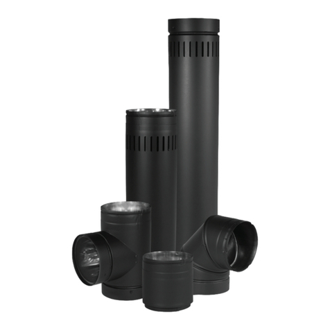
DuraVent DVR User manual

1
MODEL DVR (ROUND) TYPE-B
GAS VENT INSTALLATION
INSTRUCTIONS
Readthroughalloftheseinstructionsbeforebeginningyourinstallation.
Failuretoinstallasdescribedintheseinstructionswillvoidthemanufacturer’s
warrantyandmayhaveaneffectonyourhomeowner’sinsuranceandUL
listingstatus. Keeptheseinstructionsforfuturereference.
REFERENCES
(1)NationalFuelGasCode,alsoreferredtoasNFPA54andANSIZ223.1
(2)SimpsonDura-Vent'sSizingHandbook,availablefromSimpsonDura-
Vent CONTENTS
REFERENCES .......................................................................................... 1
GENERAL INFORMATION.................................................................. 1
PLANNING ............................................................................................... 2
STEPS FOR TYPICAL INSTALLATION ........................................... 4
BUCKET SUPPORT................................................................................ 9
COMBINATION TOP........................................................................... 10
ADJUSTABLE ELBOWS...................................................................... 11
MALE AND FEMALE ADAPTORS .................................................. 12
RELINING MASONRY CHIMNEYS.................................................. 13
MAINTENANCE .................................................................................... 19
GENERAL INFORMATION
Type B Gas Vents are for venting listed Natural Gas or Liquid Propane
CategoryIappliancesonly. Theapplianceslistedbelowtypically(butnotalways)
useTypeBventsystems.
Boilers Furnaces
WaterHeaters UnitHeaters
RoomHeaters DuctFurnaces
FloorFurnaces DecorativeGasAppliances
SimpsonDura-VentTypeBVentSystemsmaybeusedonothergas-burning
appliances,providedthemanufactureroftheappliancestatesintheirinstallation
instructionsthatTypeB-ventisacceptable. DonotuseTypeB VentsforCategory
MH6357

2
FLASHING
HIGH WIND TOP
DuraCap TOP
SEE TABLE 2
1 INCH MINIMUM
CLEARANCE
(ALL SIDES)
B-VENT
1 INCH MINIMUM
CLEARANCE
(ALL SIDES)
FIRESTOP
SPACER
DOTTED LINES
SHOW POSSIBLE
OFFSET IN ATTIC
SPACE
Fig 1
ENCLOSURE
CEILING SUPPORT
/FIRESTOP
VENT CONNECTS
TO APPLIANCE
STORM
COLLAR
II,III,orIVgasappliances. TypeBVentshallnotbeusedtovent flueproducts
fromincinerators,combinationgas/oilappliances,oil-fired,orwood-burning
appliances. If there is a question about the use of Type B Vents, contact the
appliancemanufacturerorSimpsonDura-Vent'sEngineeringDepartmentfor
furtherinformation. PLANNING
1.Appliances. Carefullyreviewtheappliancemanufacturer'sinstallation
instructionsforpositioningtheunit,anyspecialventingorconnectorrequire-
ments,andverifythatitisaCategoryIapplianceoranappliancethatrequires
the use of Type B gas vent.
2. Placement. The place-
mentoftheventandfittingsmust
be in accordance with Local
Codes, as well as accepted vent-
ing practices. If more than one
appliance is to be connected to
oneventingsystem,thecommon
ventmustbecorrectlysized. Itis
agoodideatomakeasketchofthe
proposed installation, labelling
the components you will need.
Adjustable Pipe Lengths are
availabletomakeupodd lengths.
Minimizethenumberofturnsand
lateral runs, as the National Fuel
Gas Code places limitations on
these. A45°turnispreferableto
a 90° turn. The appliance refer-
encematerialshouldbeconsulted
atthis time,as wellas any Local
Authorityhavingjurisdiction. In
most localities, building permits
are required for any new appli-
ances, or modifications to exist-
ingventingsystems.

3
3. Figures 1, 2, & 3
show examples of some
typical residential in-
stallations.
4. Clearance to
Combustibles. A1-inch
clearance(airspace)to
combustible materials
must be maintained,
when using Simpson
Dura-Vent Round B-
Vent,regardlessofthe
pipediameter.
5.CombustionAir.
Refertoapplianceinstal-
lationinstructionsandlo-
calbuildingcodestoen-
surecompliancewithre-
quired volume of com-
bustion air for each ap-
pliance installed .
6. Slope. Ifthevent-
ingsystem containslateral (horizontal)components, theyshall bepositioned
so they have an upwards slope away from the appliance of not less than 1/4-
inch rise per foot of run. (Horizontal vent installed in attics, unconditioned
area, or between floors have further restrictions, please consult your local
building codes for specific limitations.)
7.TerminationArea. Examinetheareawheretheventsystemwillterminate.
Theheightoftheterminationabovetheroofisdeterminedbythe roofpitch,and
alsoit'sproximitytoadjacentwallsorobstructions. ConsultTable2 onpage 9
for proper termination height requirements. Vent pipe with 3"-12" diameter
must terminate at least 2 feet higher than an adjacent wall or obstruction, if it
WATER HEATER
WITH DRAFT HOOD
LATERAL
FURNACE
CONNECTOR RISE
CEILING SUPPORT /
FIRESTOP
90° ADJUSTABLE
ELBOW
INCREASER
TOTAL
VENT
HEIGHT
B-VENT
PIPE
B-VENT TEE
WATER HEATER
CONNECTOR RISE
FAN ASSISTED
FURNACE
Fig 2

4
iswithin8 feet. Ventpipewith 14"or largerdiameter mustterminateat least
2 feet higher than an adjacent wall or obstruction, if it is within 10 feet.
8. Connector Rise. Plan a minimum of one foot vertical connector rise
comingout of eachappliance.
STEPS FOR TYPICAL INSTALLATION
1. Location. BuildingCoderequirestheappliance(s)tobelocatedasclose
totheventaspossible. Afterconsultingthelocalcodes,applianceinstallation
instructionsandanyotherapplicablereferencematerialdeterminetheoptimum
location for the appliance(s).
2. PenetrationPoint. Locateandmarkthecenterofthepenetrationpoint
through the ceiling or the wall. Refer to Step 3 or 4, as appropriate.
3. Ceiling Support. For a ceiling supported system, install the Square
Firestop/SupportasshowninFigures6,7,and8. TheFirestopSupportmust
beframed inand thedimensions are shownin Table1 andshown in Figure 4.
Dura-Connectinstallation
procedures are contained in a
separateinstruction,obtainable
fromyourDura-VentDealer,or
fromSimpsonDura-Vent. The
clearance to combustibles for
Dura-Connect is one inch. It
maynotbeusedtopassthrough
wallsor ceilings,nor mayit be
placedinatticsorcrawlspaces.
Itmaybeusedwhereversingle
wall connector pipe is used.
1 INCH MINIMUM
CLEARANCE
(ALL SIDES)
FURNACE
CONNECTOR RISE
B-VENT USED AS
CONNECTOR
45°/60°
ADJUSTABLE
ELBOW
DURA-CONNECT
FLEXIBLE SINGLE
WALL CONNECTOR
WATER HEATER
CONNECTOR RISE
LATERAL
TOTAL
VENT
HEIGHT
FAN
ASSISTED
FURNACE
WATER HEATER
WITH
DRAFT HOOD
Fig 3
B-VENT WYE

5
Firestop Supports are
currently manufactured for
pipe sizes of 3" through 12"
only. Larger sizes may be
locallyfabricatedfromsheet
metal, provided that the
mandatory 1-inch clearance
is maintained, the pipe is
adequatelysupported,andthe
installation is acceptable to
Local Authorities. In
multistory buildings, a Firestop/
Spacer must be provided at every
floor /ceiling level other than the
firstfloorwhichrequiresasupport.
4.WallThimble. Forathrough-
the-wall system, install the Wall
Thimble,asshowninFigure5. The
Wall Thimble is designed to ac-
commodate walls up to 6 inches
thick. If you have thicker walls, a
sleeve extension should be fabri-
cated and attached to the existing
sleeve . Do not fill the air space
between the B-vent Pipe Section
andtheWallThimblewithinsula-
tion,althoughanRTV-typesealant
may be applied around the flange
and nail heads if desired.
5.PipeAssembly. Sectionsof
SimpsonDura-Ventroundpipeare
joinedtogetherbyliningup the fe-
maleendofthelockinglugwiththe
maleendslot,pushingthemtogether,
andturningclockwisetotwistlock.
Refer to Figure 9. Sheet metal
screwsarenotneededfor3"through
PIPE SIZE STOCK NUMBER OF
CEILING SUPPORT FRAMED INSIDE
DIMENSIONS (X & Y)
FIG 4
3 INCH 1440 7-3/8" X 7-3/8"
4 INCH 1441 7-3/8" X 7-3/8"
5 INCH 1442 9-1/8" X 9-1/8"
6 INCH 1443 9-1/8" X 9-1/8"
7 INCH 1444 11-1/8" X 11-1/8"
8 INCH 1445 11-1/8" X 11-1/8"
10 INCH 1446 13-1/8" X 13-1/8"
12 INCH 1447 13-1/8" X 13-1/8"
Table1
EXISTING
SHEET ROCK
FRAMINGMEMBERS
REQUIRED FOR
SUPPORT
EXISTING
JOISTS
Fig 4
Fig 5

6
8" diameter pipe. However, if desired, use 1/
4-inchlongsheetmetalscrewsfor3"through8"
diameter pipe. Never penetrate the inner liner
withscrews. For10"through16"diameterpipe,
SimpsonDura-Vent recommendsusingamini-
mumof(4)3/8"sheetmetalscrewsperjoint,and
a minimum of (6) 3/8" sheet metal screws per
joint for 18" and larger diameters. Each Pipe
Section is labelled, and an arrow shows the
direction of the exhaust flow. For ceiling sup-
ported installations, place a Pipe Section, or
assembledPipeSections,throughtheholeinthe
SquareFirestopSupport,andtightentheClamp. TheClampwillrestinside
theCeilingSupport,andpreventthePipeSectionsfromdroppingdown. The
PipeSection(s)shouldprotrudeaminimumofoneinchbelowtheceiling. An
optional Pipe Collar is available for decorative purposes.
6. Connectors. Only Simpson Dura-Vent connectors should be used
betweentheappliancesandtheventingsystem. SomeappliancesrequireTypeB-
Ventasacompletededicatedsystemfromthefluecollaroftheappliancetothe
terminationofthevent totheoutsideatmosphere. SimpsonDura-Vent’slisted
flexible,single-wallcorrugatedaluminumconnector,called“Dura-Connect”can
HANGER
STRAPS
Fig 7
NAILS
(4 REQ)
B-VENT
PIPE
SECTION
PIPE COLLAR
(OPTIONAL)
CLAMP
Fig 8
CLAMP AND
HARDWARE
HANGER
STRAPS
CEILNG
SUPPORT
Fig 6

7
be used in many applications when a
B-Ventconnector is not required.
7. Elbows. When Elbows are re-
quired,strapthePipeSectionsand/or
Elbows in place using Wall Straps.
Supporttheoffsetsothattheweightof
theoffsettingpipeisnotbearingdownon
theelbows,asshowninFigure10.
8.TeesandWyes.TeesandWyes
areusedtocombineconnectorsfrom2
ormoreappliancesintoacommonvent
as shown in Figures 2 and 3. A Tee
should be used in a through-the-wall
application, (Figure 11), as they have a removable Tee Cap (available as a
separateitem)attachedtothebottom.ThisTeeCapmayberemovedinorder
to inspect the system, or to clean out debris or collected condensate from the
commonvent. WallStrapsshouldbepositionedeveryfourfeet tosupportthe
verticalcommonvent.
9.Enclosures. Anyportionoftheventwhichpassesthroughanoccupied
areamust be enclosed,to prevent accidental damage to the system,as well as
burns. Figure 1 (page 2) shows a
systemwhichpassesthroughanoccu-
pied second floor. Simpson Dura-
Vent doesnotrecommendinstallation
ofB-Vent Pipe onthe outsidewall of
a building, particularly in cold cli-
mates. If it is necessary to do this,
enclosetheoutsideportionofthesys-
teminachase,asshowninFigure11.
It would be wise to consult the Local
Authoritypriortoconstruction. Note
that the enclosure requires an access
door for inspection and maintenance
purposes.
10.Terminations.WherethePipe
Sectionspassthroughtheroof,ahole
must be cut to provide a minimum
STEP 1
STEP 2 STEP3
Fig 9
Fig 10
WALL
STRAPS
EXISTING
STRUCTURE
ELBOW GORES
WALL
STRAP
1 INCH
MINIMUM
CLEARANCE TO
COMBUSTIBLES
AT ALL POINTS
45/60°
ELBOW
CEILING SUPPORT

8
clearance (air space) of 1 inch
betweenthePipeandconstruc-
tionmaterials. Straightlengths
of pipe are run up above the
roof.(seetable2)ARoofFlash-
ing is placed down over the
pipe, and adjusted so it fits
tightlyagainsttheroof,withthe
PipeSectionheld in a position
maintainingthe1inchminimum
clearance from combustibles.
The Flashing is then nailed to
the roof. The roofing material
(shingles, asphalt paper, etc.)
shouldoverlapthetopedge(up-
hill side) of the Flashing. A
non-hardeningsealantshouldbe
used around the edges of the
flashingbasewhereitmeetsthe
roof, as shown in Figure 12.
Non-hardeningsealantisplaced
around the joint between the
Flashing and the vertical Pipe
SectionandtheStormCollaris
then placed over this joint, to
make a watertight seal. Add
sufficient Pipe Sections to at-
taintheheightspecifiedinTable
2. To connect the Top to the
pipe, hold Top by its collar,
slidecollaroverlockinglugsof
pipe, and twist-lock clockwise.
Tops of diameters greater than
16 inches do not twist-lock, but
are affixed with sheet metal
screws.
11. Inspection. This com-
Fig 11
1 INCH
MINIMUM
CLEARANCE
(ALL SIDES)
WALL STRAP FRAMED
ENCLOSURE
WALL
THIMBLE
WALL STRAP
REMOVABLE
ACCESS DOOR/PANEL
FOR CLEANNG AND
INSPECTION
TEE
TEE CAP
GAS
APPLIANCE
TOPS ARE
INTERCHANGEABLE
Fig 12
STORM
COLLAR
1 INCH
MINIMUM
CLEARANCE
1 INCH
MINIMUM
CLEARANCE
SEE
TABLE 2
SEALANT
DuraCap
TOP
HIGH
WIND
TOP
FLASHING

9
pletes the installation steps.
Conductafinalinspectionto
insure that all joints are se-
cure, the system is properly
supported, and is mechani-
callysound. Especiallyverify
that the one-inch clearance
tocombustiblesrequirement
has been met, and that ad-
equatecombustionairwillbe
furnishedto theappliance.
BUCKET SUPPORT
1. Description. The
BucketSupport(showninFigure13)is
for properly supporting the B-vent be-
tween 16 or 24-inch O.C. joists or
rafters, or for providing a transition fit-
ting
be-
tween
Dura-
Con-
nect
SingleWallConnectorandtheB-ventPipe
Sections. Amaximumof20feetofTypeB
Gas Vent may be supported. Note that the
BucketSupportmustbeinstalledpriortothe
sheetrock.
2. Assembly. After you have deter-
minedwheretheB-ventshouldbelocated,
assemble theBucketSupportandBrack-
ets. Nailtheassemblytothebottomsideof
the joist material as shown in Figure 14.
AftertheSupportBucketisinplace,scribe
and cut out a hole in the sheet rock 1/8"
largerthanthediameteroftheBucket,and
GAS VENT SYSTEMS USING VENT CAPS LISTED BY UNDERWRITER’S
LABORATORIES MAY TERMINATE IN ACCORDANCE WITHTHIS VENT
TERMINATION TABLE
ROOF PITCH MINIMUM HEIGHT
FEET METERS
FLAT TO 7/12 1 0.3
OVER 7/12 TO 8/12 1.5 0.46
OVER 8/12 TO 9/12 2 0.61
OVER 9/12 TO 10/12 2.5 0.76
OVER 10/12 TO 11/12 3.25 0.99
OVER 11/12 TO 12/12 4 1.22
OVER 12/12 TO 14/12 5 1.52
OVER 14/12 TO 16/12 6 1.83
OVER 16/12 TO 18/12 7 2.13
OVER 18/12 TO 20/12 7.5 2.29
OVER 20/12 TO 21/12 8 2.44
Table 2
Fig 13
Fig 14
CONTINUATION
OF B-VENT SYSTEM
B-VENT
BUCKET SUPPORT
RAFTER 16 OR
24 INCHES O.C.
NAIL
HERE
CEILING
SINGLE-WALL
CONNECTOR
(DURA-CONNECT)

10
nailintoplace. RunthePipeSectionsthroughtheholeintheBucketSupport,
connecttheDura-ConnectSingleWallConnector,andattachtheClampso
thatitrestsinsidetheBucket,andwill
supportthePipe. AdjustthePipetothe
desiredheightand tightentheClamp.
This will provide a complete engi-
neeredsupportsystem.
COMBINATION TOP
1.Description. TheCombination
Top,provides aneasily installed, safe
andefficientB-VentTopandFlashing,
asonelightweightunit. Thetwobasic
componentsandtheassembledunitare
showninFigure15. TheCombination
Topis designed to accommodate roof
pitches from flat to 6/12, and is avail-
ablefor3"through6"diameterB-Vent
pipe.
2.Location. Locatethepointinthe
underside of the roof where the system
is to penetrate, using a plumb bob or
level.
3.Hole.Removesufficientroofing
material to cut a hole in the roof which
will allow a minimum of 1 inch air
space between the B-Vent and com-
bustible roofing materials.
4. Flashing. Position the Flash-
ingsotheholeisdirectlyovertheend
of the pipe, as shown in Figure 16.
RunthetopedgeoftheFlashingunder
the roof covering, nail as required,
Fig 15
1" MINIMUM
Fig 16
Fig 17
APPLY SEALANT
ALONG TOP, LEFT,
AND RIGHT EDGES,
AND ON NAIL
HEADS
RUN TABS ON
FLASHING UP
THRU RAISED
SLOTS ON CONE
Fig 18
AND THEN
FOLD THEM
OVER TO
HOLD CONE
TO FLASHING
1-1/2 TO 3
INCHES

11
and seal with a non-hardening sealant, as shown in Figure 17. Seal all nail
heads.
5. Height. Add sufficient Pipe Sections of B-Vent until the system
terminates1-1/2"to3"abovethecollaroftheFlashingasshowninFigure16.
6. TopCone. Slipthe TopCone overthe Flashing,sothevertical straps
ontheFlashingcoincidewiththeslotsatthebaseoftheCone. Slipthestraps
up through the slots as shown in
Figure18. AdjusttheTopConeto
a generally vertical position.
HoldingtheTopConeinposition,
bend the straps down as shown.
7. This completes the
installation. Conduct a final
inspection of the job to insure
properjoints,correctprocedures,
sealed nail heads, etc.
ADJUSTABLE ELBOWS
1.Purpose. Thissectionfur-
nishes supplemental information
concerning AdjustableElbows,both 90°and 45°/60°.
2.Connections. Inadditiontotwistlockingtheelbows,theconnectionmay
befurthersecuredbyusingsheetmetal screwsatthejointwherethemaleand
femalepartsoverlap,providedthat thescrewsdonotpenetrate theinnerliner
asshowninFigure19. Onescrewperjointisnormallysufficient. Use#8Pan
Headsheetmetalscrewswhicharenolonger
than1/4inch. LiberaluseofWallStrapsfor
additionalsupportisrecommended. Donot
allowtheweightoftheoffsettingpipetobear
down on lower elbow.
3. 90°Elbows. Figure20. Theinstaller
should apply pressure to the section at the
points indicated by the arrows. This will
prevent the adjacent sections of the elbow
from turning, as the next pipe or fitting is
twist-locked on. This is important, because
once these sections start rotating, the elbow
Fig 19
DRILL 1/8"
DIAMETER
HOLE. DO NOT
PENETRATE
INNER LINER.
3/8"
SHEET
METAL
SCREW 1/4-
INCH LONG
Fig 20

12
does no longer have a 90° angle.
4. 45°Offsetswith90°Elbows.
Figure 21 shows a 90°Adjustable
Elbowbeingutilizedtoaccomplisha
45°offset. ThisElbowiscompletely
adjustablefrom0°to90°. Pleasenote
that the centers of the upper sections
tendtodisplacebyaslightamount,as
they are rotated. Again, screws (not
longer than 1/4") may be used to
securethejoint. WallStrapsshould
alsobeutilizedtoenhancethestabil-
ityoftheventsystem.
MALE AND FEMALE ADAPTORS
1. Description. The male and female adaptors
enable an installer to connect Simpson Dura-Vent B-
ventcomponentstoanexistingTypeBgasventsystem
manufactured by the following companies: American
MetalsProducts,HouseholdMfg,Hart&CooleyMfg,
MetalFab,Inc,WhiteMetalProducts,AirJet, Mitchell
MetalProducts.
2. ConnectingintoExistingCompetitorsSystem.
To connect into an existing competitors gas venting
systemfrombelow,orfromtheapplianceside,connect
aFemaleAdaptorasshowninFigure22,insuringthat
theinnerlineroftheadaptorisoutsidetheinnerlinerof
theexistingpipe. Pushtheadaptorasfarupasitwillgo,
andtightenthelockingboltuntiltheconnectionissnug.
3. Extending an Existing Competitors System.
Tocontinueanexistingcompetitorssystemuptowards
the termination using Dura-Vent Type B Gas Vent,
connectaMaleAdaptortothelastsectionofthesystem,
asshowninFigure23,insuringthattheinnerlinerofthe
Adaptor fits smoothly inside the Pipe or fitting below it. Push the Adaptor
downasfarasitwillgo,andtightenthelockingboltuntiltheconnectionissnug.
Fig 21
FEMALE
MALE
DISPLACE-
MENT
10°
EXISTING
SYSTEM
B-VENT
ADAPTOR
(FEMALE)
Fig 22
EXISTING
SYSTEM
B-VENT
ADAPTOR
(MALE)
Fig 23

14
inyourmeasurements.
(b) Pipe and
Fitting Requirements.
Thebottom5footsection
ofventwillbeFlexPipe
(used to get around the
smoke shelf, and to
connecttotheappliance).
The remainder will be
rigid B-Vent Pipe
Sections. For each pipe
joint, subtract 1-1/2 inches.
(c). Connector. Readtheappliancemanufac-
turer'sinstructionsforconnectingtheFlexPipetothe
appliance.Inmostcases,aDraftHoodConnector willberequiredasshown
in Figure 26. If you are not sure, contact the appliance manufacturer for
clarification.Placetheapplianceoutinfrontofthefireplacearea,asshownin
Figure27,andinstalltheDraftHoodConnector,orotherdeviceinaccordance
withtheapplianceinstructions. The
FlexPipeCouplingmaybeableto
attach directly to the appliance.
(d). Flex Pipe Assembly.
Assemblefirst RigidPipe Section
to the Flex Pipe, insuring that the
"UP"arrowsareinfact,pointingup.
Pushthesectionstogetherandtwist
to lock. Screws are not required,
however if you desire to use them,
use#8 sheetmetalscrews1/4-inch
long,beingcarefulnottopenetrate
the inner liner. Repeat this process
for the remainder of the Pipe Sec-
tions,andlowertheassemblydown
the chimney. Lower it below it's
normalpositionasshowninFigure
28. (e). PositionandConnect
Fig 26
DRAFT HOOD
CONNECTOR
Fig 27
APPLY
NON-HARDENING
SEALANT GAS RELINING
TERMINATION
ASSEMBLY
MASONRY
ANCHORS
Fig 28 NON-HARDENING
SEALANT
TRIM BASE
TO FIT
MASONRY

15
Fireplace. Push the gas fireplace towards the
firebox,andconnecttheFlexPipefemalecou-
pling to the appliance, or to the appropriate
connector as specified by the appliance manu-
facturer. If insufficient space is available be-
tweenthetopoftheappliance,andthefireplace
opening,anaccessopeningintheoppositeside
of the masonry chimney may be necessary.
Positionthegasapplianceonit'sfinallocation,
again complying with the manufacturer's in-
structions in regards to location. Install any
shields or covers at this time.
(f). AdjustHeight.Gotothetopofthechimneyandpulltheventsystem
uptoitsdesiredheight.Inmostcases,thiswillbe12inchesabovethemasonry
surface. Make a mark on the Pipe Section even with the top of the masonry
surface. If the top of the pipe is near a steep roof (more than 7/12 pitch) ,use
the height as stated in Table 2.
(g). TerminationAssembly. TrimtheBasePlateoftheTermination
Assemblytocover themasonryopening. RefertoFigures 28and29. Slipthe
Basedownover theprotruding PipeSection. Use masonryanchors andnon-
hardeningsealanttosecuretheBasetothemasonry.
(h).Clamp. PullthePipeupthroughtheBasetothemark,whichyou
previouslymade. SliptheClampdowntothemark,andtightenitsecurelytothe
Pipe. TheClampwillthensupporttheentireventingsystem. SliptheStormCollar
downoverthePipeSection,andsealthejointwitha non-hardeningsealant.
(i). Top. Install the Top, as shown in Figure 28.This concludes the
proceduresforinstallingagasfireplaceinanexistingmasonryfireplace. Conduct
afinalinspectionofthesystem,andverifythatthemanufacturer'sinstallation
instructionshavebeentotallycompliedwith.
2. GasAppliance Venting Into theSideWallof a Masonry Chimney.
(a). Locate Appliance. Set the appliance in it's desired position, and
mark the center of the hole where the lateral Pipe Section is to pierce the
masonrychimney. Insurethemanufacturer'srequirementsarecompliedwith,
particularlyinregardstodistancesfromcombustiblesurfaces.RefertoFigure
30.(b). Hole in Masonry. Move the appliance aside, and break out the
masonry,formingaholelargeenoughforthePipeSectiontogetthrough,andalso
APPLY NON-
HARDENING
SEALANT AROUND
THESE SURFACES
MASONRY
ANCHORS
Fig 29
BASE OF GAS
RELINING
TERMINATION
ASSEMBLY
TRIMMED AND
SHAPED TO
FIT MASONRY AND
FLUE TILE

16
largeenoughtoreachthroughandholdtheTee,whileconnectingthehorizontal
PipeSection. Analternateprocedureistomaketheholeonlylargeenoughfor
thePipeSectiontopassthrough,andconstructanaccessgateontheotherside
ofthe masonry chimney. Do not mortarto thepipe..
(c). Tee. ATeeisinstalledatthebottomendoftheassembledvertical
Pipe Sections, as shown in Figure 30. The Tee has a removable Tee Cap at
the bottom, for cleaning and condensate removal. If the configuration of the
building permits it, a clean-out access gate is recommended.
(d). VerticalPipeSections. RuntheassembledverticalPipeSections
(withthe Teeattached tothe bottom),down thechimney, untilthe horizontal
branch of the Tee is opposite the hole in the masonry.
(e). AdjustHeight. HoldtheassembledPipeSectionsinthisposition,
andmakeamarkevenwiththetopsurfaceofthemasonrychimney. The vertical
Pipe Sections should protrude 12 inches (in most cases) above this mark. If
thetopofthepipewillbenearasteeproof(morethan7/12pitch),usetheheight
as stated in Table 2.
(f).TerminationAssembly. TrimtheBasePlateoftheTermination
Assemblytocoverthemasonryopening. RefertoFigures28and29. Slipthe
Base down over the protruding Pipe Section. If necessary, use masonry
anchorsandnon-hardening sealanttosecure theBaseto the masonryorbend
base to secure. (g). Clamp. Pull the Pipe up
throughtheBasetothemark,whichyou
madepreviously.SliptheClampdown
tothemark,andtightenitsecurelytothe
Pipe. TheClampwillthensupportthe
entireventingsystem. SliptheStorm
Collar down over the Pipe Section,
andsealthejointwithanon-hardening
hightemperatureRTV.
(h). Horizontal Pipe
Section(s). Run the horizontal Pipe
Section(s) through the hole in the
masonry, and connect it firmly to the
Tee, either by reaching through the
hole,andholdingtheTeewhiletwisting
thePipeSection,orbyholdingtheTee
Fig 30
GAS
APPLIANCE
GASRELINING
TERMINATION
ASSEMBLY
TEE
DRAFT HOOD
CONNECTOR
(IF REQUIRED)
TRIM COLLAR

17
throughtheaccessdoorwhilesomeonetwist-locksthePipeSectiontoit. Use
an Adjustable Pipe Length as needed to obtain a specific location for the
appliance. MakeamarkonthehorizontalPipeSectionflushwiththevertical
face of the masonry, for referencing the vertical position. Slip a Pipe Collar
overthehorizontalPipeSectionandinstalltheremainingfittingsasshownin
Figure 30. A minimum of 12 inches of connector rise is required.
(i).Insulation.PullthePipeCollartowardsthe90°Elbow. Fillinthe
gapbetweenthemasonryandthehorizontal
PipeSectionwithceramicfiberinsulation
or fiberglass, as shown in Figure 31. If
fiberglass is used, remove any paper
backing. Thefillingmaybefacedoffwith
grout, if desired. Push the Pipe Collar
back flush with the masonry. Make any
final adjustments on the Adjustable
Length Pipe (if used), and tighten the
clampingbolts.
TROUBLESHOOTING
1. Purpose. This section is intended as a general maintenance and
troubleshootingguide,andassuch,cannotencompassallconfigurationsorvent
designs. Forproblemsencountered whicharebeyond thescopeof thissheet,
contactyourDura-VentDealer,Distributor,orSimpsonDura-Vent'sEngineering
Department. Itisimperativethattheone-inchclearance(airspace)defined
in these instructions be maintained. In most cases, a one-inch minimum
clearancemustbemaintainedtocombustibles. Theonlyexceptionsare4-inch,5-
inchand6-inchOvalB-ventwhichareinstalledwithinstudwalls. OvalB-vent
andBWVentarethesubjectofaseparateinstallationinstruction,andarenot
discussedhere. Inthesecases,theclearancesareestablishedbythelistedFirestop
SpacersdescribedintheinstructionsforOvalB-Vent.
2.Appliance. Readtheapplianceinstallationinstructionscarefully,insuring
thattheprescribedclearancesaremet,andthatitisaCategoryIappliance.
3.Spillage. Spillagefromanappliancedrafthoodmaycausecondensation
on windows, or odors that the occupant may notice. Spillage may be caused
byanincorrectlysizedventsystem,blockageoftheventsystem,oradowndraft
inthevent. Othercausesare:excessivelateralruns,toomanyelbows,improper
pitch to lateral runs (1/4 inch per foot of run is correct), fans or ventilation
systemsinthesamegeneralareaasthegasappliance,orwindconditionsatthe
CERAMIC
FIBER
INSULATION
Fig 31

18
vent cap.
4. Blockage. Check the system for blockage by removing the cap, and
looking down into the vent with a flashlight. Check for bird nests, debris,
rodents, insects, or other obstructions. If nothing is found, inspect the entire
systemforphysicaldamage.
5.Downdraft. Downdraftsaregenerallycausedbythesystem'stermination
beingtooclosetoanadjacentwall,parapet,orotherstructure. Ifthecapiswithin
eightfeetofsuchanobstruction,itmustalsobeatleasttwofeetaboveit. Alsoinsure
thatthetopisattheheightprescribedforyourroofpitchinTable2. Inadequate
combustionair isalso amajor causeof downdraftproblems. Appliances like
clothesdryersorotherexhaustingappliancesinthesameutilityroomcancause
downdraftproblems.
6. Condensate/Corrosion. Continuouscondensate can cause corrosion
(rusting)ofvents,tops,appliancedrafthoods,andothercomponentsofthesystem,
as well as the inside of the appliance. This situation can be extremely
dangerous, and corrective action must be taken immediately.Common
causesofcorrosionarelistedbelow: Ifindoubtcallaprofessionaltoinspectthe
vent. (a) Iftheventsystemislocatedinanareawherespraycansorsolventsare
usedextensively,(laundryareas,orpaintshops,forexample),thehalogenated
compounds get into the combustion air. When they are burned, they form
compoundsthatcausecorrosion. Thecorrectiveactioninthiscase,istoisolatethe
appliance,andgettheairsupplyfromoutside,oranuncontaminatedarea.
(b) Condensatemaybecaused byincorrectsizing of theventsystem.
Followtheproceduresinthevarioussizingpublications toobtainthecorrectsizes
for connectors and vents. Other causes are: excessive lateral runs, too many
elbows,coldatticsandcrawlspaces,andlargeareasoftheexteriorportionsofthe
ventingsystemexposedtocoldweather. Asageneralrule,lateralsshouldbeheld
toaminimum,andbe nolongerthan75%of theverticalheightofthe system.
Condensatemay initiallyappearasbeadsontheoutsideoftheconnectororvent.
7. Construction. Laterals, offsets, and vertical components should be
securelysupportedwithwallstraps,aspreviouslydescribed. Componentsof
theventwhichareinoccupiedareasshouldbeenclosedtopreventaccidental
contactanddamagetotheventsystem. Insurethatinsulation,buildingmaterials,
or debris do not extend into the required clearance spaces. In cold climates,
theexteriorportionsoftheventshouldbeenclosedinachase. Outsideportions
of the vent system with may be painted with high temperature paint to help

19
prevent rusting and corrosion on the exterior surfaces.
MAINTENANCE
1. Anannualinspectionisrequiredtomaintainwarrantyofyour
SimpsonDura-VentB-Ventsystem. YouwillneedtoinspecttheCap,Vent
Pipe,ConnectorPipe,andtheconnectiontotheappliance.
2. VerifythatthesealantaroundtheFlashingandStormCollarisintact.
Resealasneeded. RemoveCap. HoldCapbythecollaronly,andunlockby
twistingcounterclockwise,andthenpullup. GrabbingtheCapbytheouter
edgeor topcan cause damage to theCap.
3. InspectCapforanyphysicaldamageordamagefromcorrosion.
Lookforanyforeignmaterialinsidethecaporvent. (Example: bird'snest,
leaves,etc.)
4. Shinealightdowninsideoftheventpipe. Lookforanyevidenceof
damage,corrosionorexcessivecondensation. Also,lookforanydisconnected
sectionsoftheventpipeorconnectorpipe. Refertotheinstallationinstructions
toreconnectpipesections. Ifpipesectionsaredamagedorcorroded,replace
immediately!
5. ReplaceCapbygrabbingcap(bycollaronly),andslideontopipe
sectionandtwist-locking(clockwise).
6. Inspectapplianceconnectorandmakesurethattheventissecurely
connectedtotheappliance.
7. Damagedorcorrodedpartsshouldbereplacedimmediately!
Failuretodosocanleadtoanextremelyhazardoussituation!
8. Followyourappliancemanufacturer'srecommendedinstructionsfor
inspectionyourappliance.

20
SIMPSON
DURA-VENT,INC
PO Box 1510
Vacaville,CA
95688-1510
Vicksburg,MS
(800)-835-4429
(707)-446-4740 (FAX)
November1998
L204A
SimpsonDura-Ventofferstheindustry’sonly twenty-five year warranty onTypeBgasvent
system and is UL listed. This warranty is in effect from the date of installation and includes
all components and fittings. Simpson Dura-Vent warrants the following products: All Fuel
ClassAChimney-Dura/Plus®and Dura-Chimney®;CloseClearanceConnectorPipe-DVL®;
Type B Gas Vent and Pellet Vent® Chimney for a period of twenty-five years from date of
installation. Warrantyincludesallcomponentfittings,exceptraincaps,whichiscoveredfor
fiveyearsfromdateofinstallation. DirectVentGS®iswarrantedfortenyearsfrom thedate
of installation. Dura/Connect® is UL listed, approved by ICBO, BOCA and SBCCI and is
warranted for ten years from the date of installation. DuraFlex® pipe and fittings is UL and
ULC listed and is warranted for ten years from the date of installation. Warranty includes
component fittings, except cap assembly which is covered for five years from date of
installation. Dura-Black® drip free stovepipe is warranted for five years from the date of
installation. Dura/Liner®isULandULClistedandiswarrantedfortwenty-fiveyearsfromthe
dateofinstallation. Allwarranties,whetherexpressedorimplied,shallbelimitedtoreplacement
(exclusive of installation costs) of our product found to be defective under its warranty and
shallbeconditionaluponcompliancewiththemanufacturer’srecommendedinstallationand
maintenance procedures and intended use of the product, and providing all recommended
installation and maintenance instructions are followed. All products must be maintained by
periodicinspectionandcleaningasneeded,includingchimneyexposedtoweathercontaining
corrosive elements or contaminated intake air, due to storage of corrosive agents near the
appliance. Always refer to warranty specifics for each product line.
SIMPSONDura-VentCo.,Inc.AllRightsReserved,1998
Table of contents
Other DuraVent Fan manuals

DuraVent
DuraVent PelletVent UL 641 User manual

DuraVent
DuraVent DirectVent Pro User manual

DuraVent
DuraVent polypro User manual

DuraVent
DuraVent DirectVent Pro User manual

DuraVent
DuraVent duraplus User manual

DuraVent
DuraVent DIRECT-TEMP Co-Linear Insert Kit User manual

DuraVent
DuraVent DURATECH PREMIUM User manual
DuraVent
DuraVent DuraTech Canada User manual

DuraVent
DuraVent DuraSeal DS User manual
DuraVent
DuraVent duraplus htc User manual