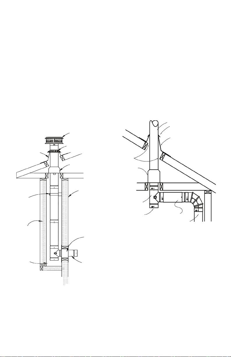
NOTE: DIAGRAMS & ILLUSTRATIONS ARE NOT TO SCALE.
NOTE: DIAGRAMS & ILLUSTRATIONS ARE NOT TO SCALE.
5
Type B Gas Vent
for Category II, III
or IV gas appli-
ances, or for any
gas appliance
which requires
either a pres-
sure-tight or liq-
uid-tight venting
system.
All sizes of Model BV Type B Gas Vent may
be used in single and multistory buildings. All
Model BV Type B Gas Vents may be used for
both individual and multiple appliance venting.
Model BV Type B Gas Vents are to be installed
and used in accordance with the “National
Fuel Gas Code”, NFPA 54, the “Standard for
Chimneys, Fireplace and Venting Systems”,
NFPA 211, the “International Fuel Gas Code”.
In Canada, Model BV Type B Gas Vents are
to be installed and used in accordance with
the “Canadian Fuel Gas Installation Code”,
CSA-B149.1-00, and/or applicable local/
regional codes. Model BV Type B Gas Vent
is also suitable for use in existing, otherwised
unused and new masonry chimneys to protect
the chimney from damaging eects of moist
combustion products from the appliances listed
above. NEVER USE Model BV Type B Gas
Vent on any appliance that is not listed and
approved for venting with Type B Gas Vent.
Model BV Type B Gas Vent is designed for
venting listed Natural Gas or Liquid Propane
Category I gas appliances equipped with draft
hoods and other listed gas appliances spec-
ied for use with Type B gas vent producing
ue gas temperatures not in excess of 470°F
(245°C). These appliances include (but are
not limited to) the following types: furnaces,
boilers, water heaters, room heaters, unit
heaters, duct furnaces, oor furnaces, and
decorative appliances.
DO NOT USE Model BV Type B Gas Vent for
wall furnaces “Listed” for use with Type BW
Gas Vents only, incinerators and appliances
Listed for use with chimneys only, combination
gas-oil burning appliances, and appliances
which may be converted readily to the use of
solid or liquid fuels. DO NOT USE Model BV
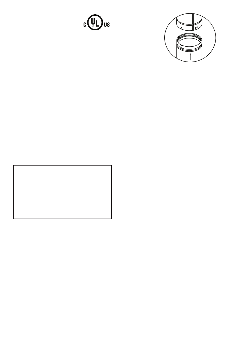
3. GAS VENT JOINT METHOD
All joints of Model BV Type B Gas Vent
must be secured using the “DuraLock”
feature. To use the DuraLock feature, ori-
ent sections as shown in Fig.1 and push
adjacent pieces together until fully engaged.
NOTE: Some local jurisdictions require a sup-
plemental screw(s) at joints to prevent disen-
gagement of the joint. Although not required
under the terms of the UL Listing because of
the integral couplers, screws are permitted to
be installed at the joints in 3” through 8” vent.
In such case, the screws should be located
aproximately 1/4” from overlapped edge and
must be maximum 1/4” in length so they do not
pierce or deform the inner liner.
The DuraTab® feature provides the equivalent
of using a screw. Once engaged (with nger or
Failure to follow the installation
instructions could cause FIRE,
CARBON MONOXIDE POISONING, OR
DEATH. If you are unsure of installation
requirements, call the Phone Number
listed on the instructions, 1-800-835-4429
or visit www.duravent.com.
WARNING
1. GAS VENT DESIGNATIONS/
TYPES OF APPLIANCES
DuraVent Model BV Type B Gas
Vent parts LISTED and produced under the
Factory Inspection and Follow-up program
of Underwriters’ Laboratories, Inc. carry the
LISTING MARK illustrated here. Type B Gas
Vent has been tested, and listed using all of
the supports, restop, etc., described herein.
Deletion or modication of any of the required
parts or materials may seriously impair the
safety of your installation, and void the certi-
cation and or warranty of this vent. It is of the
utmost importance that this vent be installed
only in accordance with these instructions.
Model BV Round is listed to UL 441 and CAN/
ULC-S605 in diameters of 3” to 30”. Model
BVO Oval is listed to UL 441 in diameters of
4” to 6”. Model BVO Oval is not available in
Canada.
CAUTION: WEAR GLOVES WHILE
HANDLING METAL PARTS TO AVOID
PERSONAL INJURY. SHARP EDGES OR
PROJECTIONS CAN CUT YOU.
2. TYPES OF APPLIANCES AND BUILDINGS
SECTION 1
FIG. 1 - 3” to 8” BV