Review the step-by-step directions before
beginning your installation.
CEILING SUPPORTED
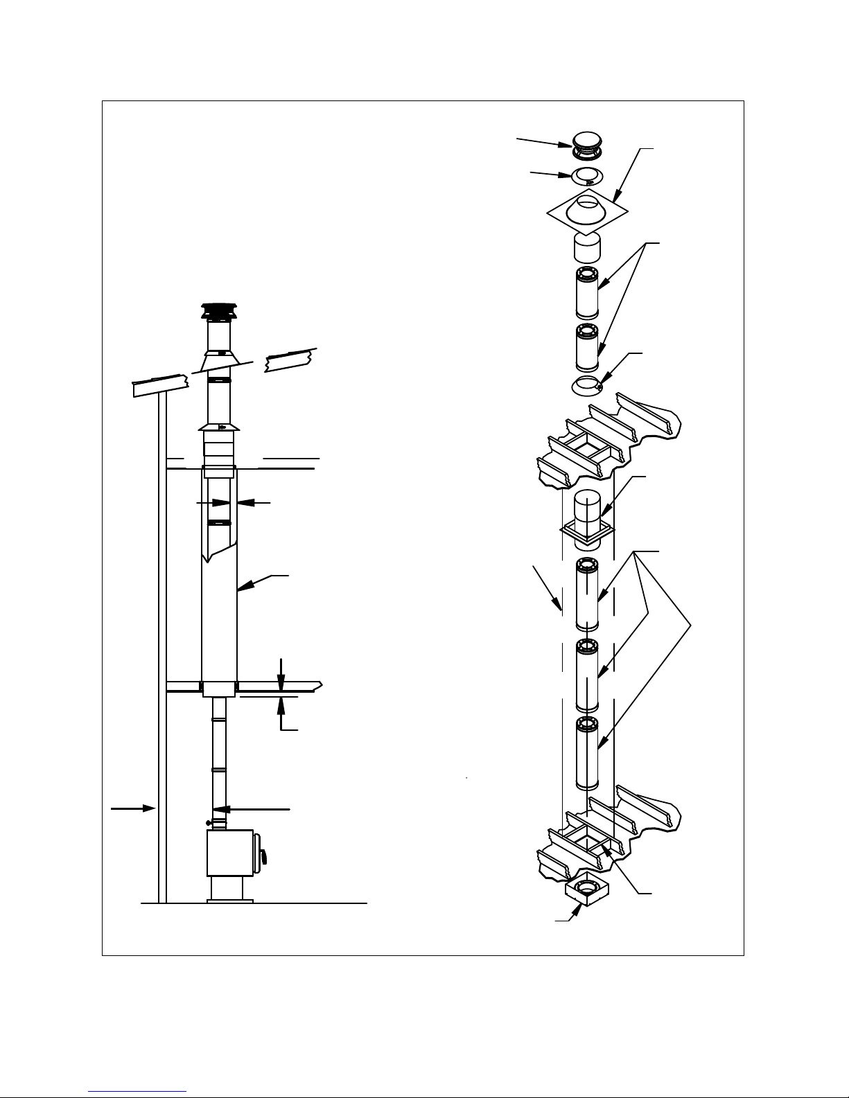
1. Place Appliance: Position the appliance
according to the manufacturer’s instructions.
The ue outlet collar should be placed
between the rafters or joists above,
if possible.
2. Frame Support Opening: Use a laser
level or drop a plumb bob to the center of
the appliance’s ue outlet and mark this
center point on the ceiling. Refer to Table 2
for framing dimensions. Mark a cutting line
around the center point to the dimension
required in Table 2. Cut a square hole in the
ceiling for the Support Box. Frame a level,
square opening centered over the hole which
you have cut. (Figures 3 and 4).
3. Install Support: For installation into a
at ceiling, you may use a Square Ceiling
Support Box, a Round Ceiling Support Box, a
Reduced Clearance Support Box, or the CAS
Ceiling Support. Note: each of the Ceiling
Supports act as a restop at the ceiling level;
an additional restop is not needed at that
level. Each Ceiling Support can support a
maximum of 40-feet (12.2 m) of chimney.
The CAS Ceiling Support is only used when
installing the CAS system. Refer to the
DuraPlus HTC CAS Installation Instructions for
directions on how to install the remainder of
the Combustion Air System. For the Square
Ceiling Support Box, refer to the cathedral
ceiling installation below. The bottom of the
Round Ceiling Support must extend at least
3 inches (75 mm) below the nished ceiling.
Level the Ceiling Support and secure it to the
framing using at least three 8-penny nails per
side (min. of 12 total). Alternatively, you may
use 1-1/2” #8 wood screws (min. of 12 total),
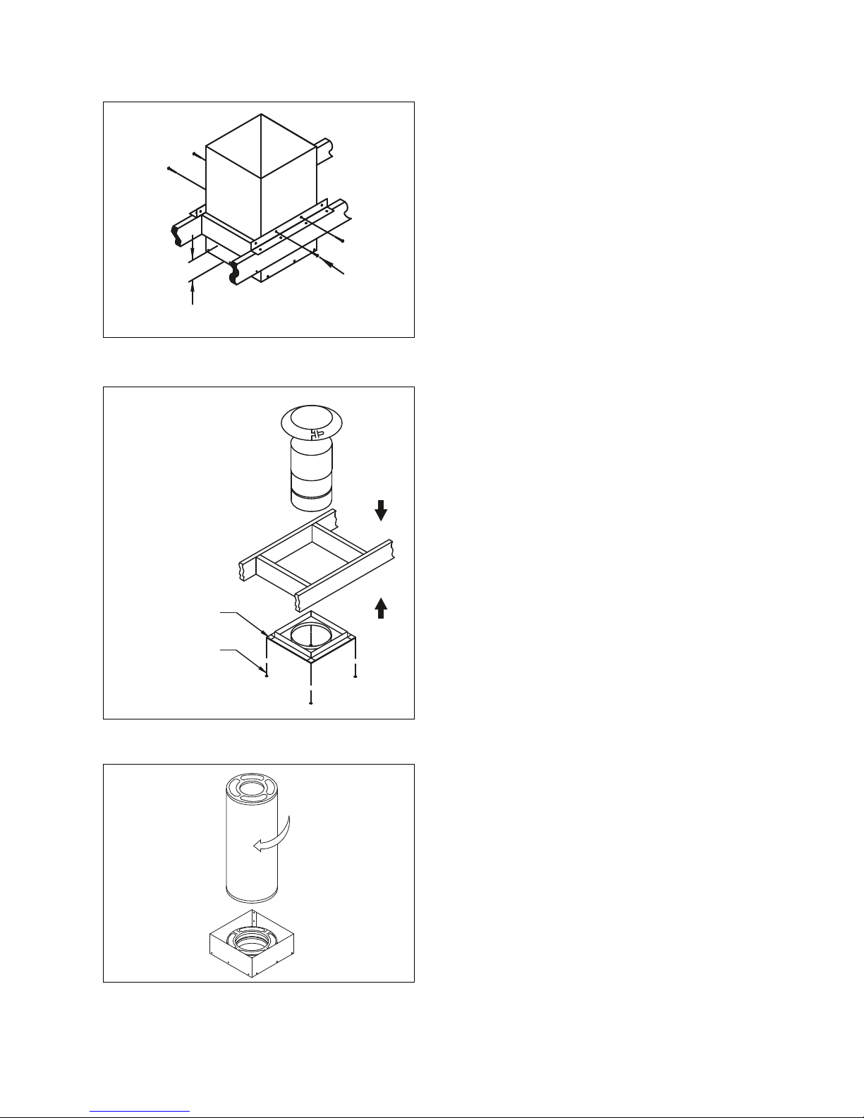
instead of nails. Next, secure the two-piece
Trim Collar to the framing members using
the (6) 1-1/4” long, round-head wood screws
provided (Fig 6).
For installation into a cathedral ceiling, you
must use the Square Ceiling Support Box,
Reduced Clearance Support Box, or the CAS
Ceiling Support and the two-piece Trim. The
bottom of the square portion of the Support
Box must be a minimum of 3 inches (75 mm)
lower than the nished ceiling at the lowest
side of the penetration (Fig 5 & 6). Level the
Support Box . Support Box Guide Rails are
available for Cathedral Ceiling Support Boxes
to help ensure the Support Box is level during
installation. Before installing the Support Box,
align the Guide Rails level onto the Support
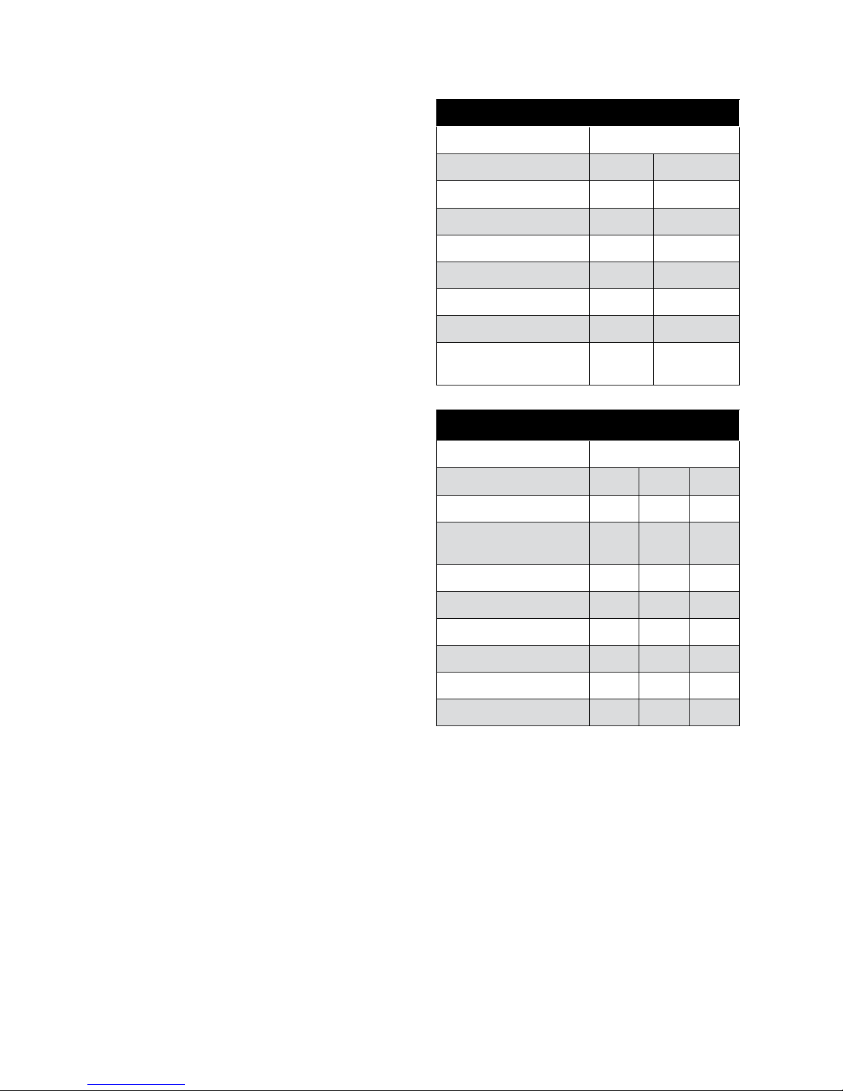
DuraPlus HTC Component Framing Dimensions
Square Ceiling Support Box 14-1/2" 370mm
Round Ceiling Support Box 14-1/4" 362mm
Reduced Clearance Support Box 12-1/4" 312mm
CAS Ceiling Support 14-1/2" 370mm
Wall Thimble 14-1/4" 362mm
CAS Wall Thimble 14-1/4" 362mm
Firestop Radiation Shield 14-1/2" 370mm
Reduced Clearance Firestop
Radiation Shield 12-1/4" 312mm
DuraPlus HTC Support Chimney Height Supported
6" 7" 8"
Square Ceiling Support Box 40-ft 40-ft 40-ft
Reduced Clearance Square
Ceiling Support Box 40-ft 40-ft 40-ft
CAS Ceiling Support Box 40-ft 40-ft 40-ft
Round Ceiling Support 40-ft 40-ft 40-ft
Roof Support 30-ft 30-ft 30-ft
Tee Support 35-ft 30-ft 25-ft
Tee Re-Support 30-ft 25-ft 25-ft
Extended Wall Bracket 35-ft 30-ft 25-ft