SET UP
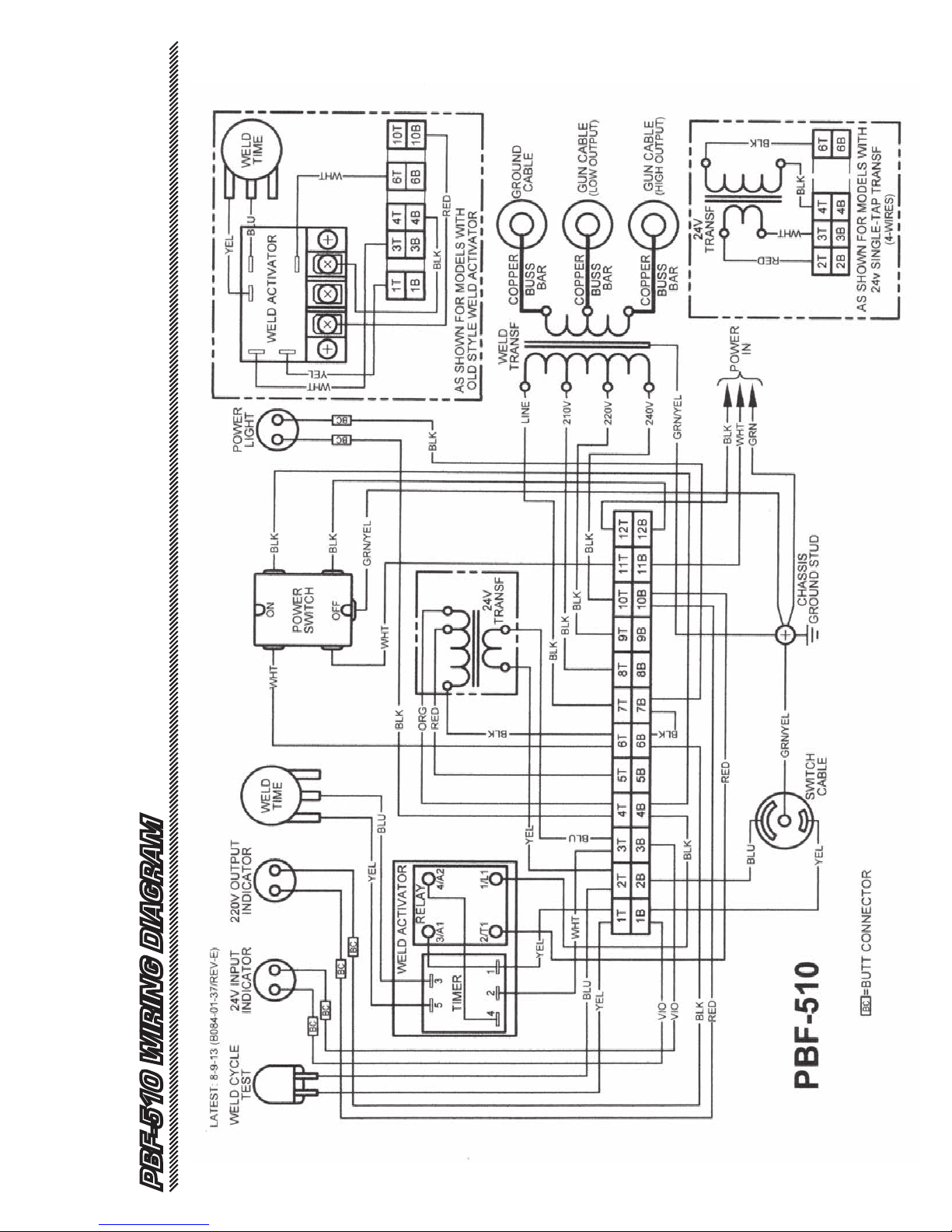
Connect the PBF-510 to a 100 amp power supply. (208-
230 volts - 60 cycle). The PBF-510 unit uses 208-230 volt
single phase. To wire to 208-230 volt single phase, the green
lead is ground and the white and black leads are power. It is
suggested that the unit be permanently wired into a 100 amp
disconnect box fitted with 100 amp slow blow fuses.
ELECTRICAL REQUIREMENTS
PBF-510 AS A BENCH TOOL
Where the duct is too large to put on a bench, snap the
ground clamp onto the duct and secure the insulation quickly
by welding the Clip Pins inside or outside of the ducts as
required. Eliminate the heat mark on the duct by using the
simple “heat sink” included on opposite the side of weld.
WHEEL PBF-510 TO THE WORK
TIMER ADJUSTMENT
The PBF-510 has been designed and built to withstand rug-
ged shop usage. Constant, trouble-free operation is assured
with a minimum of maintenance. The GUN TIP, the GROUND
CLAMP and all CABLE CONNECTIONS should be kept clean to
maintain a good electrical contact. Wire brush the parts to
remove any oxidation or adhesive that may have accumulated
during the fastening operation.
"HEAT SINK"
The timer dial facing you on the front panel of the unit, deter-
mines the duration of the weld cycle. For maximum efficiency
of the unit, the weld cycle should be set for the shortest
length of time necessary to provide a good weld. An excessive
amount of time does not improve the weld. On the contrary,
the resulting weld may not be an acceptable one. It is recom-
mended that at the start of a production run, using a given
length of pin with a given gauge of metal, the operator take
a few moments to determine the minimum timer setting to
perform the job and leave the timer at that point.
NOTE: There is a common misconception that the longer the
weld time, the stronger the weld. This is not true. It is impor-
tant that you follow the above instructions for maintaining
the minimum weld time.
MAINTENANCE
Included with your PBF-510 is a simple “heat sink” tool that
looks somewhat like a cookie cutter. This tool, when placed
behind the point of weld on bare metal, will eliminate any mark
on the metal by dissipating the heat generated from the point
of weld. The use of a copper sheet on the work bench will also
eliminate this mark.
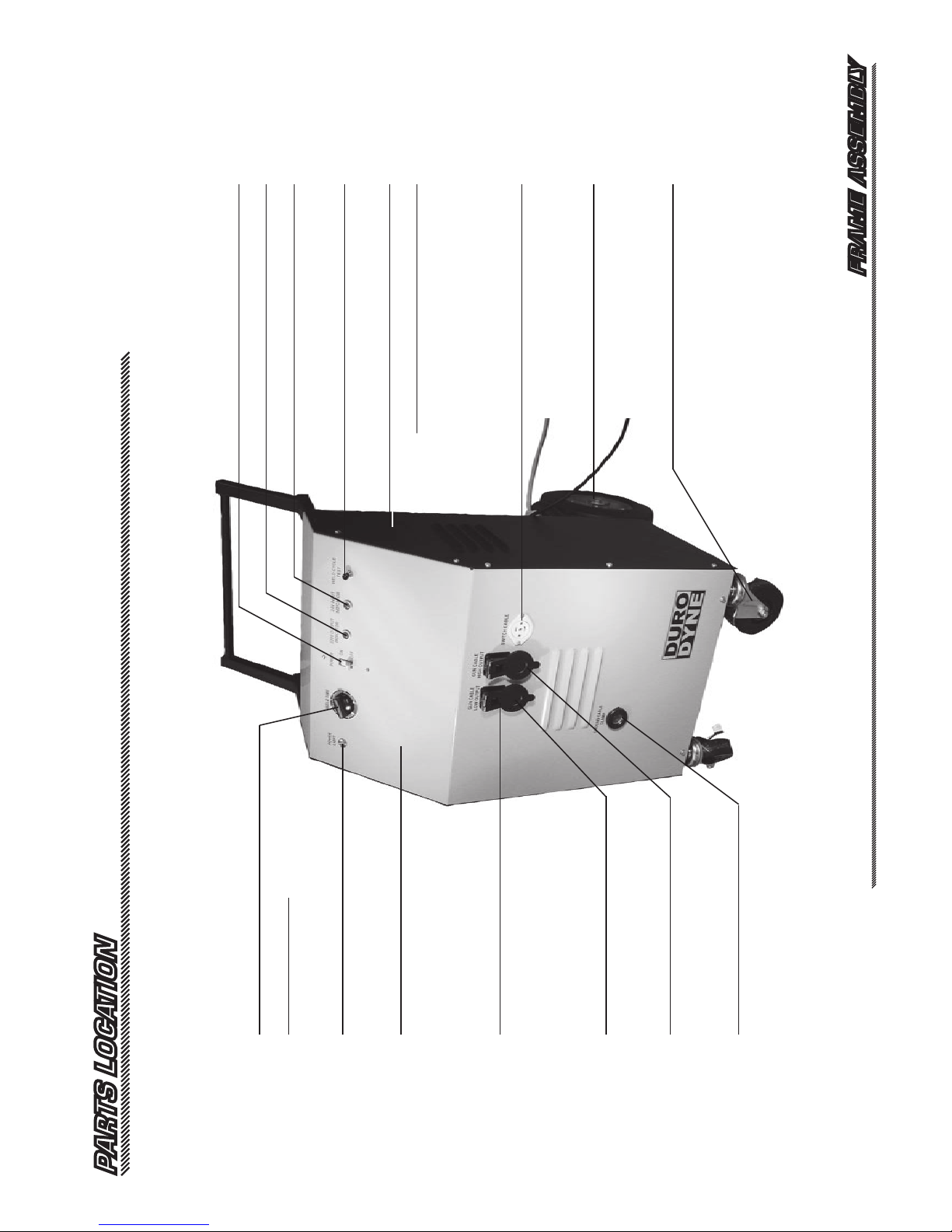
1. Plug the gun cable camlock
connector into either the high
or low gun female camlock (A).
(The HIGH tap produces about
10 volts, typically used for long
pins or heavy gauge material.
The LOW produces 5 volts,
typically used for light gauge
material.)
2. Plug the switch cable into the
switch cable socket (B).
3. Plug the ground cable cam
lock connector into the ground
female camlock (C).
To use your work bench as a welding table, set the PBF-510
alongside the work bench. Cover the bench top with a copper
sheet, (.025 inch) which will act as a permanent ground when
the duct work is placed on the table top. Attach the ground
clamp to the duct work or copper bench top. The Clip Pins
will quickly weld every time with no burn marks or wasted
pins due to misfires.
The PBF-510 has been designed and built to withstand rugged
shop usage. The Indicator lights on the front panel will help
you to diagnose minor problems. If your PBF-510 fails to
operate, follow this simple procedure to find the defective
component.
1.
Pull the trigger and watch the lights, the green light (24 volts)
and then the red light (220 volts) should flash on and off.
2. If only the green light comes on, go to step 4
3. If neither light comes on, press the WELD CYCLE TEST
switch on the front panel.
a. If both lights flash and the transformers do not hum go
to step 5.
b. If both lights flash and the transformers hum, the
problem is either a bad trigger switch or bad switch
cable.
c. If only the green light flashes, go to step 4
d. If neither light flashes, replace the 24 volt
transformer.
4. Replace the weld activator.
5. The problem is probably a bad weld transformer. Call
technical service for further assistance.
(1-800-899-3876)
SERVICE
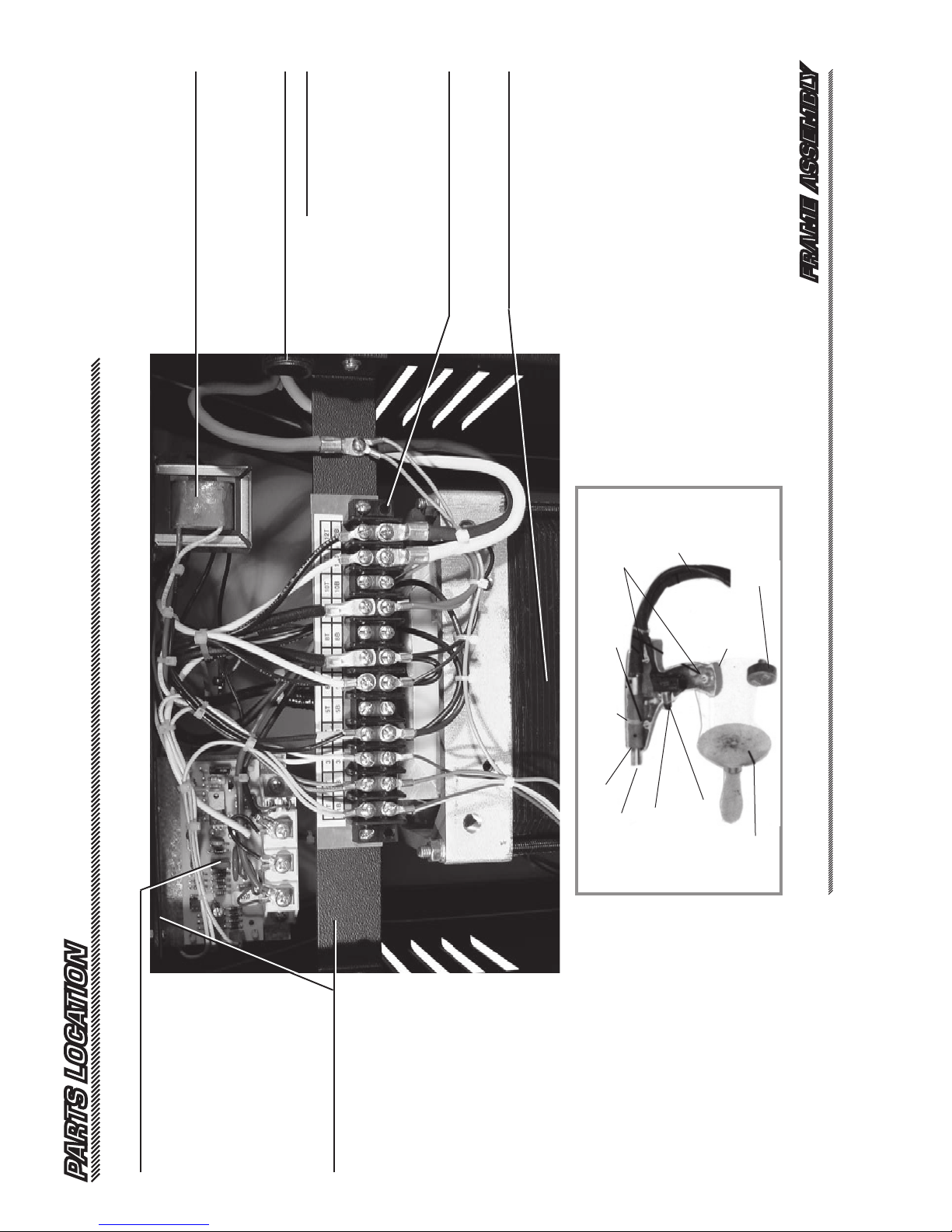
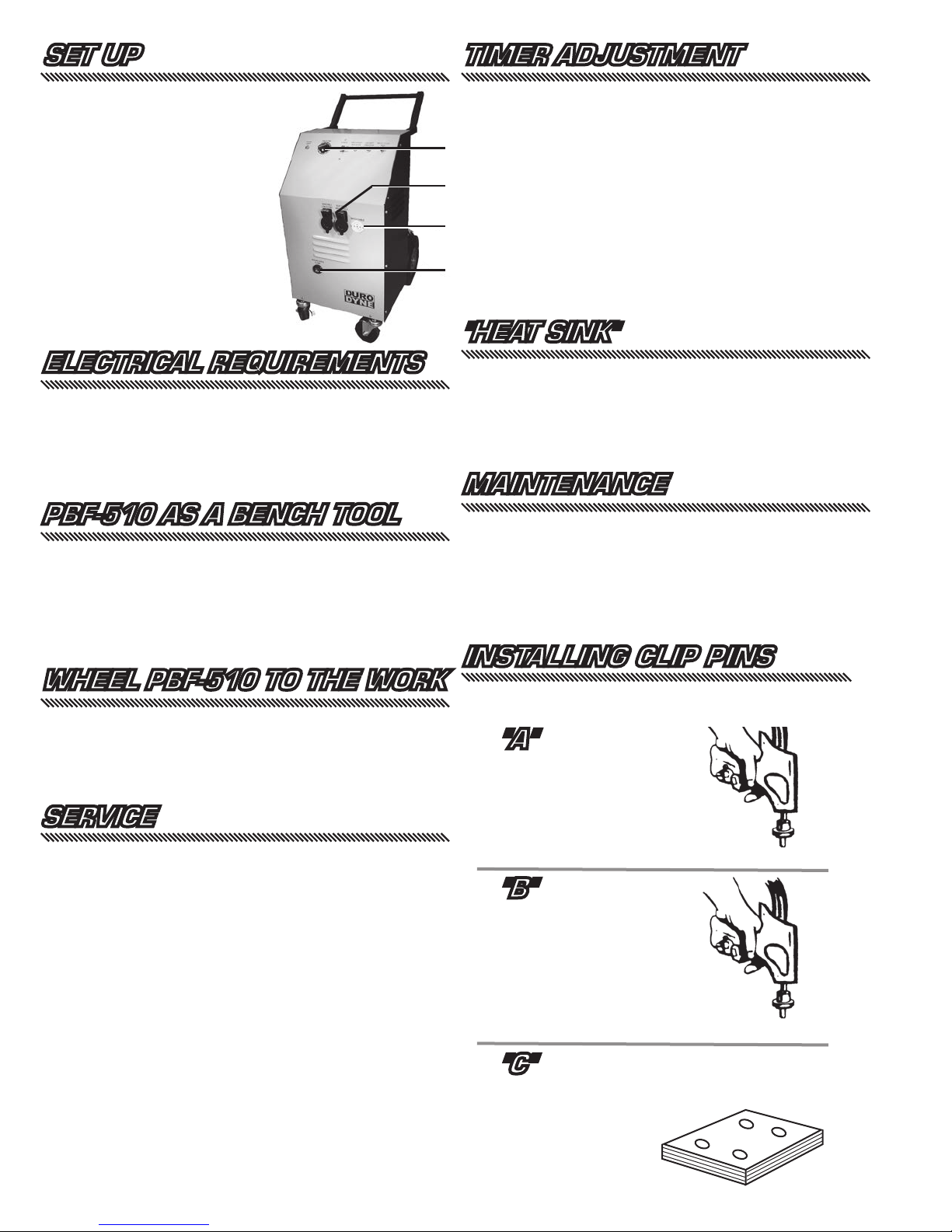
INSTALLING CLIP PINS
Clip Pins are welded as easily as "A", "B", "C".
"A"
Press down through the insu-
lation, twist the gun, pull the
trigger. Do not release the
trigger until the timer cycle
has ended.
"B"
Position the Clip pin on the
Magnetic tip of hand gun.
The Clip Pins are permanently
welded in position flush with the
insulation.
"C"
B
Timer
PBF-510
A
C