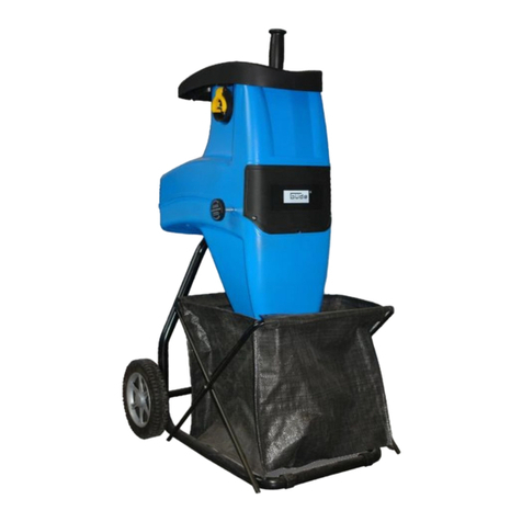
DuroStar ES-1600 Operation manual

ECO-SHREDDER
BY
DUROSTAR
OWNERSOPERATINGMANUAL
CHIPPER
/
SHREDDER
/
MULCHER
MODEL
ES1600
SPECIFICATIONS:
Horse
Power:2.5HP
HopperSize:
15-1/4"
x
10-3/8"
SideChute:
1-3/8"
x
2-5/16"
R.P.M:
3450
THANK
YOUFOR
PURCHASING
AN
ECO-SHREDDER,
CHIPPER
/
SHREDDER
/
MULCHER.
Your
new
Chipper/Shredder/Mulcher
has
beenengineered
and
manufactured
tothe
higheststandards
of
dependability,
ease
ofuseand
operator
safety.Properly
cared
for,
it
will
give
you
years
of
rugged,
trouble-free
performance.
CAUTION:Carefullyreadthroughthisentireowner'smanualbeforeusingyour
new
Chipper
/
Shredder
/
Mulcher.
Pay
closeattention
tothe
Rules
for
SafeOperation,Warnings
and
Cautions.
If
youuseyou
Chipper
/
Mulcher
/
Shredderproperly
and
only
for
what
itis
intended,
you
willenjoyyears
of
safe,
reliableservice.
Thank
you
again
for
buyingDUROSTARequipment.
SAVE
THIS
MANUAL
FOR
FUTURE
REFERENCE

RULES
FOR
SAFE
OPERATION
The
purpose
of
safetyrules
isto
attract
your
attention
to
possibledangers.
The
safetysymbols
andthe
explanations
withthemrequireyourcarefulattention
and
understanding.
The
safetywarnings
donotby
themselveseliminate
any
danger.
The
instructions
or
warn
ings
theygive
arenot
substitutes
for
properaccidentpreventionmeasures.
SAFETY
ALERTSYMBOL.Indicatescaution
or
warning.
Maybe
used
in
conjunctionwithother
symbols
or
pbtures.
WARNING:
Failure
to
obey
a
safety
warning
can
result
in
seriousinjury
toyou
or
to
others.Always
follow
the
safetyprecautions
to
reduce
theriskof
fire,electricshock
and
personal
injury.
WARNING:
Donot
attempt
to
operatethistool
until
you
havereadthoroughly
and
understood
completely,
safety
rules,
etc.
contained
in
this
manual.Failure
to
comply
can
result
in
accidents
involving
fire,electric
shock
or
seriouspersonal
injury.Saveownersmanual
and
reviewfrequently
for
continuing
safeoperation
and
instructing
others
who
mayuse
thistool.
The
operation
ofany
tool
can
result
in
foreign
objects
being
thrown
intoyoureyes,which
can
result
in
severe
eye
damage.
Beforebeginningpowerequipmentoperation,
ahways
wearsafety goggles
or
safetyglasseswithside
shields
anda
full
face
shield
whenneeded.Wear
a
wide
visionsafetymask
foruse
overeyeglasses
or
standard
safety
glasseswithsideshields.
1.
KNOWYOURPOWERTOOL.Readowners
manualcarefully.
Leam
rts
applications
and
limitations
as
well
asthe
specific
po!ential
hazards
related
to
thistool.
2.
GUARDAGAINSTELECTRICALSHOCK
BY
PREVENTINGBODYCONTACTWITH
GROUNDED
SURFACES.
For
example,
pipes,
radiators,
ranges,refrigeratorenclosures.
3.
KEEPWORKAREACLEAN.Clutteredareasinvite
accidents.
4.
AVOID
DANGEROUS
ENVIROMENT.
Don't
use
power
tools
in
damp
orwet
locations
or
expose
to
rain.
Keepworkareawelllit.
5.
KEEP
CHILDREN
AND
VISITORSAWAY.
Visitors
should
wearsafetyglasses
andbe
kept
a
safe
distancefromworkarea.
Donotlet
visitorscontact
tool
or
extension
cord.
6.
STORE
IDLE
TOOLS.
When
notin
use,tools
should
be
stored
ina dryand
high
or
lockedplace
outof
reach
of
children.
7.
DON'TFORCE
TOOL.
It
will
dothejob
better
and
safer
atthe
rate
at
which
it
was
deskjned.
8.
USE
RIGHTTOOL.Don't
force
smalltool
or
attachment
todothejobofa
heavydutytool.Don't
use
a
tool
fora
purpose
not
intended.
9.
DRESSPROPERLY.
Donot
wearloose
cbthing
or
jewelry.
They
canbe
caught
in
movhg
parts.
Rubber
gloves
and
non-skid
footwear
are
recommendedwhenworkingoutdoors.Alsowear
protectivehaircovering
to
containlonghair.
10)
ALWAYSWEARSAFETYGLASSES.Everyday
eyeglasses
haveonlyimpactresistantlenses,they
are
not
safetyglasses.
11)
PROTECTYOURLUNGS.Wear
a
dustmask
if
operation
is
dusty.
12)
PROTECTYOURHEARING.Wearhearing
protectionduringoperation.
13)
DON'TOVEREACH.Keepproperfooting
and
balance
atall
times.
Donotuse
tool
onan
unstable
support.
14)
MAINTAINTOOLSWITHCARE.Keeptoolssharp
and
clean
for
better
and
saferperformance.
Follow
instructions
for
lubricating
and
changingaccessories.
15)
REMOVEADJUSTINGKEYS
AND
WRENCHES.
Form
a
habit
of
checking
tosee
thatkeys
and
adjustingwrenches
are
removedfrom
tool
before
turning
iton.
16)
NEVER
USEINAN
EXPLOSIVEATMOSPHERE.
Normal
sparking
ofthe
motor
could
ignite
fumes.
17)
KEEPHANDLESDRY,CLEAN
AND
FREE
OF
OILAND
GREASE.Always
usea
cleanclothwhen
cleaning.Never
use
break
fluids,
gasoline,
petroleumbasedproducts
orany
strongsolvents
to
clean
you
tool.
18)
STAYALERT
AND
EXERCISECONTROL.Watch
what
youare
doing
anduse
commonsense.
Donot
rush.
19)
CHECKDAMAGEDPARTS.Beforefurther
useof
the
tool
a
guard
orany
other
partthat
is
damaged
should
be
carefully
checked
to
determine
that
it
will
operateproperly
and
perform
its
intendedfunction.
Check
for
alignment
of
movingparts,binding
of
moving
parts,
breakage
of
parts,mounting
andany
otherconditionsthat
may
affect
its
operation.
A
guard
orany
otherpartthat
is
damagedshould
be
properlyrepaired
or
replaced
byand
authorized
service
center.
20)DONOTUSE
TOOL
IF
SWITCH
DOES
NOT
TURN
ITONAND
OFF.Havedefectiveswitches
replaced
by
authorized
servicecenter.
21)DONOT
OPERATETHISTOOLWHILEUNDER
THE
INFLUENCE
OF
DRUGS,ALCOHOL
OR
ANY
MEDICATIONS.
SAVE
THESEINSTRUCTIONS
FOR
FUTUREREFERENCE
Dueto
continuedproduct
refinement
policy,
product
features
and
specifications
canand
will
changewithoutnotice.
Check
currentfeatures
and
specifications
withyourretailer.
-1
-
•
ASSEMBLEFRAME
&
WHEELS
Align
the
holes
inthe
wheels
tothe
holes
inthe
axle
section
of
the
frame
and
securetightlywith
the
bolts,
springwashers
and
nutsprovided
as
shown
in
Fig.
1.
Affix
thehub
caps
tothe
wheels.
Fig.
2
.
TOP
HOPPER
Place
theTop
Hopperonto
the
metalfeedtube
and
align
the
attaching
holes.
Secure
theoneway
screw.
•
HANDLE
Insert
the
handle
bar
into
the
handleshaftslocated
at
the
rear
ofthe
machine.Align
the
holes
inthe
handle
bar
tothe
holes
inthe
handleshafts
and
securewith
the2
knobs
as
shown
in
Fig.
4 & 5.
.
SAFTEYSWITCH
The
safetyswitchthat
is
located
onthe
cutterbase
is
activated
when
theTop
Hopperassembly
is
removed
to
help
preventaccidentalstarting.Fig.
6
.
OPERATION
Read
and
understand
the
safetyinstructions
in
this
owner'smanualbeforeusingyourECO-SHREDDER.
Connect
the
machine
toa
suitablepoweroutlet.
To
start
the
machine,place
the
On/Offswitchlocated
atthe
rear
ofthe
motor
to
"ON"position.Fig.
7.To
stop
the
machine,switch
to
the
"OFF"
position.
-2-

•
ATTACHINGMULCH
BAG
Place
a
heavydutygarbage
bag
over
thelipofthe
discharge
chute
and
secureintopositionusing
a
strap.
Fig.
8
•
MAINTENANCE
Your
ECO-SHREDDER
has
beendesigned
fora low
level
of
maintenance,
involving
routinecleaning
and
inspection.
The
motor
ofthe
machine
is
maintenancefree
and
requires
no
attention.
For
bestresults
the
bladesmust
be
keptsharp
at
all
times.
The
bladeshavedramaticallylesscuttingpower
when
dull.
The
machinewilltearratherthan
cut
when
the
blades
are
dull.Whenthisoccursrotate
the
doublesided
blades
or
replace
the
bladesimmediately.
WARNING
Before
attempting
any
maintenance,switch
the
machine
off
and
disconnect
the
powercordfrom
power
source.
•
JAMMING
If
bladesbecomejammed,switch
offthe
machine
and
disconnect
the
powercordfrom
the
powersource.Always
wear
gloveswhenattemptingmaintenance
ofthe
cutting
chamber.Unscrew
the3
securing
Top
Hopper
assembly
knobs.Remove
theTop
Hopperassembly
and
remove
the
obstructionfrom
the
cuttingchamber.
WARNING
Take
extremecare
notto
come
in
contactwith
cuttingblades.Assemble
theTop
Hopper
in
reverse
order
stated
above.
WARNING
If
ejectionchutebecomes
clogged
or
cuttingblades
becomejammed,under
no
circumstancesshould
you
place
yourhands
inthe
ejection
chute
totryto
clear
the
obstructbn
as
thiswilllead
to
serious
injury.
.
V-CUTTER
MAINTENANCE
•
Switch
the
machine
offand
disconnect
the
powercord
ensuring
all
movingparts
are
comptetely
stopped.
•
Weargloveswhenattempting
any
maintenance
tothe
cutting
blades.
•If
bladesrequirereplacing,ensure
youuse
DUROSTAR
genuine
parts.
>
DISASSEMBLY
I.
Unscrew
the3 Top
Hopperassemblyknobs
and
remove
theTop
Hopperassembly.
!.
Rotate
the
cutterbasecounterclockwise
and
place
a
piece
of
woodbetween
the
cutterbase
andthe
cutting
chamber
wall
soasto
stop
the
cuttingbasefrom
rotating.
Fig.
9
i.
Remove
the
centerholddownbolt
by
turning
it
counter
clockwiseusing
a
wrench.
t.
Remove
the
squarewasher,squarebushing,
V-cutter
and
V-cutterbase
to
expose
the
cutterbase.
•
SHREDDINGBLADESMAINTENANCE
To
inspector
replace
the
doublesidedshreddingblades
there
isno
need
to
remove
the
V-cutter
or
cutting
base.
To
remove
simplyundo
the
countersunkscrewswith
thehex
wrenchprovided
wrth
the
machine
and
turnthem180°.
Theseblades
are
double
ground
andcanbe
used
on
both
skies.
When
dull
on
bothsidesreplacewith
new
blades
and
make
sure
they
are
screwed
in
tightly.
•
ASSEMBLY
This
is
carried
outinthe
reverseorder
to
that
ofthe
disassembly
but
withcarefulinspection
ofall
components.
Ensure
that
the
cutterbase
is
assembledwith
the
scraping
platesfacingdown
towardsthe
motor
and
that
the
spring
washer
is
situatedunder
the
head
ofthe
centerholddown
bolt.
Fig.
10
Before
replacing
thetop
coverassembly,ensurethat
the
V-cutter
is
positioned
as
shown
in
Fig.
11.
Replace
theTop
Hopperassembly
and
securewith
the
three
(3)
Top
Hopper
assembly
knobs.
Fig.
10
•
CLEANING
After
use,always
wipe
clean
the
outside
ofthe
machine
to
remove
any
build
upof
materialwith
a
dampcloth.
Clean
the
inside
ofthe
cuttingchamber
and
remove
any
left
overmaterial.
-3-

•TOP
HOPPER
-
FRONT
CHUTE
The
slopingchute
oftheTop
Hopper
is
designed
to
accept
leaves
and
smallgardenclippings.Shredding
and
mulching
is
achieved
by
naturalsuction
ofthe
debristhrough
the
blade
chamber.
Donot
overload
anddo
not
feedwet,soggy
materialinto
the
machine
as
this
may
clog
the
bladechamber
andthe
dischargechute.Fig.
12
If
a
finer
mulch
is
requiredthan
is
initially
achieved,re-feed
the
mulchthroughagainuntil
the
desiredresult
is
obtained.
DONOT
FEED
SOLID
BRANCHES
THOUGH
THE
TOP
HOPPER
CHUTE.
•
SIDECHUTE
The
chutelocated
atthe
rear
ofthe
machine
is
specially
designed
to
acceptsolidgardenclippings
and
branches
upto
1-1/4"
in
diameter.
IMPORTANT:
Whenfeedinglong,largediametermaterial,controltherate
of
feed
by
pulling
back
onthe
material
soasnotto
stall
or
overload
the
motor.Fig.
13
WARNING
Do
not
under
any
circumstances
place
handsinside
the
feedingchuteswhile
the
machine
isin
operation.
Force
feeding
of
debris
isnot
necessary
due
tothe
naturalsuction
of
the
machine.
•
Motor
jamming
When
the
motorstopped
by
over
thick
branch
or
other
cause,
the
overcurrent
protective
devicewill
be
off,then
turn
offthe
switch,
usethe
"L"
hexagon
spanner
to
turn
the
motor
shaftthough
the
hole
onthe
bottom
ofthe
motor
house.
Afterresolveblock,pleaseturn
onthe
overcurrent
protective
device
and
ON/OFFswitch,
if
still
block,
please
takeapart
the
house
to
resolveagain.
•
OVERLOAD
PROTECTION
AND
MOTOR
JAMMING
If
overfeeding
clogs
the
machine
the
overloadprotection
switch
maycutoutthe
motor.
To
restart,firstswitch
the
machine
offand
disconnect
the
powercord.Unscrew
the3
Top
Hopperassemblyknobs
and
remove
theTop
Hopper
assembly
to
remove
any
cloggeddebrisfrom
the
cutting
chamber.
Ifthetop
coverassemblybecomesjammed
and
will
not
liftoff,turn
the
V-cutter
by
pushing
a
piece
of
wood
through
the
backchute
oftheTop
Hopper
to
rotate
the
V-Cutter
to
enable
the
top
coverassembly
tobe
removed.
Reset
the
motoroverbadprotection
switch.
Fig.
14.
IMPORTANT:
Before
replacing
top
coverassemblyensurethat
the
V-cutter
is
positioned
as
shown
in
Fig.
15.
Replace
thetop
coverassemblytogether
with
the
three
(3)
Top
Hopperassemblyknobsensuringthey
are
tight.
.
CONTACT
INFORMATION:
Durostar
1669
Puddingstone
Dr.
La
Verne,
CA.
91750
Ph:
800-629-3325
Fax:
800-629-2329
Email
:
-4-

DUROSTAR
POWER
EQUIPMENT
WARRANTY
Subject
tothe
warrantyconditionsbelow,this
DUROSTARproduct,(hereafter
called
"the
Product"),
is
warranted
by
DUROSTAR
tobe
free
from
defects
in
material
and
workmanship
for
a
period
of
12
monthsfrom
the
date
of
originalpurchasecoveringbothparts
and
labor.
Under
the
terms
of
thiswarranty,
the
repair
or
replacement
ofany
part
shall
beatthe
option
of
DUROSTAR
orits
authorizedagent.Should
service
becomenecessary
during
the
warranty
period,
the
ownershouldcontactDUROSTAR
directly.
In
order
to
obtainwarrantyservice
the
ownermustprovide
the
salesinvoice
and
Warranty
Certificate
to
confirmdate
of
purchase.
Thisproduct
is
sold
bythe
retailer
or
agent
as
principal
andthe
retailer
hasno
authority
from
the
company
to
give
any
additional
warranty
or
guarantee
onthe
DUROSTAR'Sbehalfexcept
as
hereincontained
or
hereinreferred
to.
Warranty
Conditions:
Thiswarrantyonlyappliesprovided
that
the
Product
has
beenused
in
accordancewith
the
manufacturer'srecommendationsundernormal
use
and
reasonablecare
(inthe
opinion
of
DUROSTAR)
and
suchwarrantydoes
not
cover
consumablecomponents,damage,malfunction
or
failure
resulting
from
misuse,
neglect,
abuse
or
used
fora
purpose
for
which
itwasnot
designed
orisnot
suited
andno
repairs,
alterations
or
modificationshavebeenattempted
by
other
than
an
Authorized
Service
Agent.
This
warranty
will
not
apply
ifthe
tool
is
damaged
by
accident
orif
repairsarisefromnormalwear
and
tear.
Accessoriessuch
as
blades
are
excludedfrom
thiswarranty.Normalconsumablepartssuch
as
carbonbrushes,bearings,blades
and
cutters
are
excludedfromthiswarranty.
DUROSTARaccepts
no
additional
liability
pursuant
to
thiswarranty
forthe
costs
of
traveling
or
transportation
ofthe
Product
toand
from
the
servicedealer
or
agent.
Nothing
herein
shall
have
the
effect
of
excluding,
restricting
or
modifying
any
condition,warranty,
right
or
liabilityimposed,
tothe
extentonlythat
suchexclusion,restriction
or
modificationwould
render
any
term
herein
void.
DUROSTAR
1669
Puddingstone
Dr.
La
Verne,
CA.
91750
Ph:
800-629-3325
Fax:
800-629-2219
Email:
THIS
WARRANTYFORM
SHOULD
BE
RETAINED
BYTHE
CUSTOMER
ATALL
TIMES.
For
yourrecord
andto
assist
in
establishingdate
of
purchase(necessary
for
in-warranty
service),please
keep
you
purchaseinvoice
and
thisform,completedwith
the
followingparticulars.
PURCHASEDFROM:
ADDRESS
OF
RETAILER:
DATE:
MODEL
NO:
SERIAL
NO:
PresentthisformwithyourPurchaseInvoicewhenWarrantyService
is
requested.
Table of contents