Durr Dental Duo Tandem User manual

EN
1811V006
9000-610-72/30
Installation and operating instructions
Duo Tandem / Quattro Tandem
0297


9000-610-72/30 1811V006 1
Assembly
6 Requirements� � � � � � � � � � � � � � � � � � � � 14
6�1 Installation/setup room � � � � � � � � � 14
6�2 Setup � � � � � � � � � � � � � � � � � � � � � � 14
6�3 Information about electrical
connections � � � � � � � � � � � � � � � � � 14
7 Transport � � � � � � � � � � � � � � � � � � � � � � � 15
8 Installation � � � � � � � � � � � � � � � � � � � � � � 15
8�1 Remove the transport locks � � � � � 15
8�2 Installing the compressor unit � � � � 15
8�3 Establishing the compressed air
connection � � � � � � � � � � � � � � � � � � 17
8�4 Pressure reducer � � � � � � � � � � � � � 18
8�5 Place a collector tray underneath � 18
8�6 Network connection � � � � � � � � � � � 18
8�7 Electrical connections � � � � � � � � � � 19
8�8 Two devices in a single
compressed air network � � � � � � � � 19
9 Commissioning� � � � � � � � � � � � � � � � � � � 20
9�1 Checking the switch-on/cut-off
pressure � � � � � � � � � � � � � � � � � � � � 20
9�2 Checking the safety valve � � � � � � � 20
9�3 Draining the condensation water � � 21
9�4 Adjusting the rate of flow at the
pressure reducer� � � � � � � � � � � � � � 21
9�5 Monitoring the device with Tyscor
Pulse � � � � � � � � � � � � � � � � � � � � � � 22
10 Adjustment options � � � � � � � � � � � � � � � 24
10�1 Adjustment of the switch-on/cut
off pressure � � � � � � � � � � � � � � � � � 24
11 Controller � � � � � � � � � � � � � � � � � � � � � � � 25
EN
Contents
Important information
1 About this document � � � � � � � � � � � � � � � 3
1�1 Warnings and symbols � � � � � � � � � � 3
1�2 Copyright information � � � � � � � � � � � 3
2 Safety � � � � � � � � � � � � � � � � � � � � � � � � � � � 4
2�1 Intended purpose � � � � � � � � � � � � � � 4
2�2 Intended use� � � � � � � � � � � � � � � � � � 4
2�3 Improper use � � � � � � � � � � � � � � � � � 4
2�4 General safety information� � � � � � � � 4
2�5 Qualified personnel � � � � � � � � � � � � � 4
2�6 Electrical safety� � � � � � � � � � � � � � � � 4
2�7 Only use original parts� � � � � � � � � � � 4
2�8 Transport � � � � � � � � � � � � � � � � � � � � 5
2�9 Disposal � � � � � � � � � � � � � � � � � � � � � 5
Product description
3 Overview� � � � � � � � � � � � � � � � � � � � � � � � � 6
3�1 Scope of delivery � � � � � � � � � � � � � � 6
3�2 Optional accessories� � � � � � � � � � � � 6
3�3 Wear parts and replacement
parts� � � � � � � � � � � � � � � � � � � � � � � � 6
4 Technical data � � � � � � � � � � � � � � � � � � � � 7
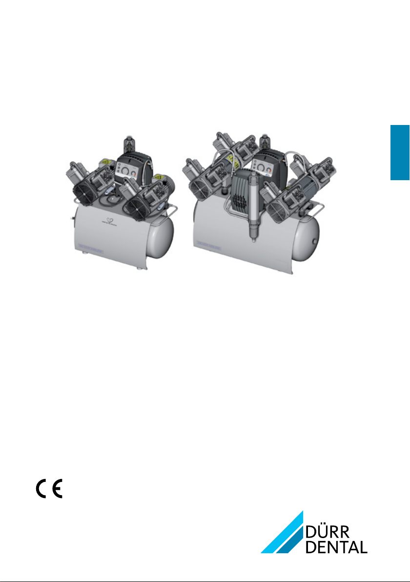
4�1 Duo Tandem� � � � � � � � � � � � � � � � � � 7
4�2 Quattro Tandem � � � � � � � � � � � � � � � 9
4�3 Distance between rubber feet � � � � 11
4�4 Type plate� � � � � � � � � � � � � � � � � � � 11
5 Operation � � � � � � � � � � � � � � � � � � � � � � � 12
5�1 Duo Tandem / Quattro Tandem� � � 12
5�2 Start-up behaviour � � � � � � � � � � � � 12
5�3 Operating panel � � � � � � � � � � � � � � 13
5�4 Tyscor Pulse (optional) � � � � � � � � � 13

2 9000-610-72/30 1811V006
Contents
Usage
12 Operation � � � � � � � � � � � � � � � � � � � � � � � 26
12�1 Operating panel � � � � � � � � � � � � � � 26
12�2 Switching the unit on/off � � � � � � � � 27
12�3 Normal operation � � � � � � � � � � � � � 27
12�4 Standby mode � � � � � � � � � � � � � � � 27
12�5 Auxiliary operation� � � � � � � � � � � � � 27
12�6 Set-up mode � � � � � � � � � � � � � � � � 27
12�7 Fault � � � � � � � � � � � � � � � � � � � � � � � 27
12�8 Emergency mode � � � � � � � � � � � � � 28
13 Monitoring the device with Tyscor
Pulse� � � � � � � � � � � � � � � � � � � � � � � � � � � 28
13�1 Monitoring operation� � � � � � � � � � � 28
13�2 Completing the task � � � � � � � � � � � 29
13�3 Creating a report� � � � � � � � � � � � � � 29
14 Maintenance� � � � � � � � � � � � � � � � � � � � � 30
14�1 Maintenance schedule � � � � � � � � � 30
14�2 Changing the filter� � � � � � � � � � � � � 31
15 Taking out of use � � � � � � � � � � � � � � � � � 32
15�1 Taking the unit out of use � � � � � � � 32
15�2 Storage of the unit � � � � � � � � � � � � 34
Troubleshooting
16 Tips for operators and service
technicians � � � � � � � � � � � � � � � � � � � � � � 35
EN

9000-610-72/30 1811V006 3
Other symbols
These symbols are used in the document and
on or in the unit:
Note, e�g� specific instructions regarding
efficient and cost-effective use of the unit�
Observe the operating instructions�
CE labelling with the number of the noti-
fied body
Manufacturer
Order number
Serial number
Dispose of correctly in accordance with
EU Directive 2012/19/EU (WEEE)�
Air
Switch off and de-energise the unit
(e�g�unplug from mains)�
1.2 Copyright information
All circuits, processes, names, software pro-
grams and units mentioned in this document are
protected by copyright�
The Installation and Operating Instructions must
not be copied or reprinted, neither in full nor in
part, without written authorisation from Dürr
Dental�
1 About this document
These installation and operating instructions
represent part of the unit�
If the instructions and information in
these installation and operating instruc-
tions are not followed, Dürr Dental will
not be able to offer any warranty or as-
sume any liability for the safe operation
and the safe functioning of the unit�
1.1 Warnings and symbols
Warnings
The warnings in this document are intended to
draw your attention to possible risks of personal
injury or material damage�
The following warning symbols are used:
General warning symbol
Warning – dangerous high voltage
Warning – hot surfaces
Warning - automatic start-up of the unit
The warnings are structured as follows:
SIGNAL WORD
Description of the type and source of
danger
Here you will find a description of the
possible consequences of ignoring the
warning�
iFollow these measures to avoid the
danger�
The signal word differentiates between four
levels of danger:
– DANGER
Immediate danger of severe injury or death
– WARNING
Possible danger of severe injury or death
– CAUTION
Risk of minor injuries
– ATTENTION
Risk of extensive material/property damage
Important information
EN

4 9000-610-72/30 1811V006
Important information
2.4 General safety information
iAlways comply with the specifications of all
guidelines, laws, and other rules and regula-
tions applicable at the site of operation for the
operation of this unit�
iCheck the function and condition of the unit
prior to every use�
iDo not convert or modify the unit�
iComply with the specifications of the Installa-
tion and Operating Instructions�
iThe Installation and Operating Instructions
must be accessible to all operators of the unit
at all times�
2.5 Qualified personnel
Operation
Unit operating personnel must ensure safe and
correct handling based on their training and
knowledge�
iInstruct or have every user instructed in han-
dling the unit�
Installation and repairs
iInstallation, readjustments, alterations, up-
grades and repairs must be carried out by
Dürr Dental or by qualified personnel specifi-
cally approved and authorized by Dürr Dental�
2.6 Electrical safety
iObserve and comply with all the relevant elec-
trical safety regulations when working on the
unit�
iReplace any damaged cables or plugs imme-
diately�
2.7 Only use original parts
iOnly use Dürr Dental parts or accessories and
special accessories specifically approved by
Dürr Dental�
iOnly use only original wear parts and replace-
ment parts�
2 Safety
Dürr Dental has designed and constructed this
unit so that when used properly and for the in-
tended purpose it does not pose any danger to
people or property� Nevertheless, residual risks
can remain� You should therefore observe the
following notes�
2.1 Intended purpose
The compressor is designed to supply com-
pressed air for dental applications�
2.2 Intended use
The air supplied by the compressor is suitable
for driving dental tools�
The compressed air generated by the compres-
sor is delivered to the pipeline system of the
surgery� The entire compressed air system must
be designed in such a way that the quality of the
compressed air generated by the compressor is
not impaired�
With this prerequisite, the air provided by the
compressor is also suitable for blow-drying
tooth preparations�
2.3 Improper use
Any other usage or usage beyond this scope is
deemed to be improper� The manufacturer ac-
cepts no liability for damages resulting from im-
proper use� In these cases the user/operator will
bear the sole risk�
WARNING
Risk of explosion due to ignition of
combustible materials
iDo not operate the unit in any rooms
in which inflammable mixtures may be
present, e�g� in operating theatres�
iThe unit is not suitable for providing an air
supply to respirators�
iThis unit is not suitable for drawing up fluids
or for compressing aggressive gases or po-
tentially explosive gases�
EN

9000-610-72/30 1811V006 5
Important information
2.8 Transport
The original packaging provides optimum pro-
tection for the unit during transport�
If required, original packaging for the unit can be
ordered from Dürr Dental�
Dürr Dental will not accept any responsi-
bility or liability for damage occurring dur-
ing transport due to the use of incorrect
packaging, even where the unit is still un-
der guarantee�
iOnly transport the unit in its original packag-
ing�
iKeep the packing materials out of the reach of
children�
2.9 Disposal
Unit
The unit must be disposed of properly�
Within the European Union, the unit must
be disposed of in accordance with EU
Directive 2012/19/EU (WEEE)�
iIf you have any questions about the correct
disposal of parts, please contact your dental
trade supplier�
EN

6 9000-610-72/30 1811V006
3.3 Wear parts and replacement
parts
The following working parts need to be changed
at regular intervals (refer to the "Maintenance"
section):
Air intake filter � � � � � � � � � � � � � � � � 0832-982-00
Fine filter� � � � � � � � � � � � � � � � � � � � 1610-121-00
Sterile filter � � � � � � � � � � � � � � � � � � 1640-981-00
Sintered filter� � � � � � � � � � � � � � � � � 1650-101-00
Any repairs exceeding routine mainte-
nance may only be carried out by quali-
fied personnel or our service�
Information about replacement parts is
available from the portal for authorised
specialist dealers at:
www�duerrdental�net�
If the mains cable of this unit is damaged
it must only be replaced by an original
mains cable from the manufacturer�
3 Overview
3.1 Scope of delivery
The following items are included in the scope of
delivery (possible variations due to country-spe-
cific requirements and/or import regulations):
Duo Tandem
Duo Tandem with 1 unit and mem-
brane drying unit*, 400 V, 3~ � � � � � � � 4152-54
Duo Tandem with 2 units and mem-
brane drying unit*, 400 V, 3~ � � � � � � � 4252-54
– Connection parts
– Collector tray
– Network cable, 3 m
– Installation and operating instructions
– Appliance log book
* with sterile filter
Quattro Tandem
Quattro Tandem with 1 unit and
membrane drying unit*, 400 V, 3~ � � � 4642-54
Quattro Tandem with 2 units and
membrane drying unit*, 400 V, 3~ � � � 4682-54
Quattro Tandem with 2 units and
membrane drying unit*, 400 V, 3~ 4682100001
– Pressure tank
– Compressor unit
– Connection parts
– Vibration dampers
– Collector tray
– Network cable, 3 m
– Installation and operating instructions
– Appliance log book
* with sterile filter
3.2 Optional accessories
The following optional items can be used with
the device:
Pressure reducer� � � � � � � � � � � � � � 6040-992-00
Sterile filter � � � � � � � � � � � � � � � � � � 1640-981-00
Network cable 3 m � � � � � � � � � � � 9000-119-071
Product description
EN

9000-610-72/30 1811V006 7
Product description
4 Technical data
4.1 Duo Tandem
Electrical data 4152-54 4252-54
Rated voltage V400 400
Mains frequency Hz 50 60 50 60
Nominal current at 8 bar (0�8 MPa) A3�1 2�5 6�2 5�0
Speed rpm 1410 1690 1410 1690
Type of protection IP 21 IP 21
Mains fuses * A10 10
* Circuit breaker fuse characteristics B, C or D in acc� with EN60898-1
General technical data
Pressure tank volume l50 50
Suction power, approx� l/min 210 255 420 505
Delivery at 5 bar (0�5 MPa) l/min 115 130 230 260
Pressure build-up phase 0 - 7�5 bar (0 -
0�75 MPa) c� s173 -99 -
Duty cycle %100 100
Start-up pressure bar (MPa) 5�5 (0�55) 5�5 (0�55)
Cut-off pressure bar (MPa) 7�5 (0�75) 7�5 (0�75)
Cut-off pressure, max� adjustable bar (MPa) 9�0 (0�9) 9�0 (0�9)
Safety valve, maximum permissible oper-
ating pressure bar (MPa) 10 (1) 10 (1)
Pressure dew point at 7bar (0�7MPa) * °C ≤+5 ≤+5
Dimensions (H x W x D) ** cm 76 x 75 x 52 76 x 79 x 52
Weight kg 64 90
Noise level *** dB(A) 68 70 69 74
* Value determined at an ambient temperature of +40°C
** Values without accessories and add-on parts
*** Noise level in accordance with ENISO1680 "Airborne noise emissions"; measured in a room
with sound damping� The levels are average values with a tolerance of ± 1�5 dB(A)� Higher val-
ues may be obtained in rooms with reverberating sound characteristics�
Filter mesh size
Compressor air intake filter µm 3
Fine filter for membrane drying unit µm 3
Sterile filter for membrane drying unit µm 0�01
Sintered filter for membrane drying unit µm 35
Network connection
LAN technology Ethernet
Standard IEEE 802�3u
Data rate Mbit/s 100
Connector RJ45
Type of connection Auto MDI-X
Cable type ≥CAT5
EN

8 9000-610-72/30 1811V006
Product description
Ambient conditions during storage and transport
Temperature °C -10 to +55
Relative humidity %max� 95
Ambient conditions during operation
Temperature °C +10 to +40
Ideal temperature °C +10 to +25
Relative humidity %max� 95
Classification
Medical Devices Directive (93/42/EEC) Class IIa
EN

9000-610-72/30 1811V006 9
Product description
4.2 Quattro Tandem
Electrical data 4642-54 4682-54
4682100001
Rated voltage V400 400
Mains frequency Hz 50 60 50 60
Nominal current at 8 bar (0�8 MPa) A4�4 4�8 8�8 9�6
Speed rpm 1440 1700 1440 1700
Type of protection IP 21 IP 21
Mains fuses * A16 16
Max� permissible mains impedance in ac-
cordance with EN61000-3-11 ** W ≤ 0�18 ≤0�18
* Circuit breaker fuse characteristics B, C or D in acc� with EN60898-1
** Mains impedance at 6 switching cycles per hour� If the number of switching cycles per hour is
higher a lower mains impedance is required�
General technical data
Pressure tank volume l90 90
Suction power, approx� l/min 420 505 845 1010
Delivery at 5 bar (0�5 MPa) l/min 215 240 430 480
Pressure build-up phase 0 - 7�5 bar (0 -
0�75 MPa) c� s156 -77 -
Duty cycle %100 100
Start-up pressure bar (MPa) 5�5 (0�55) 5�5 (0�55)
Cut-off pressure bar (MPa) 7�5 (0�75) 7�5 (0�75)
Cut-off pressure, max� adjustable bar (MPa) 9�0 (0�9) 9�0 (0�9)
Safety valve, maximum permissible oper-
ating pressure bar (MPa) 10 (1) 10 (1)
Pressure dew point at 7bar (0�7MPa) * °C ≤+5 ≤+5
Dimensions (H x W x D) ** cm 82 x 102 x 62 82 x 102 x 62
Weight kg 98 143
Noise level *** dB(A) 70 73 74 77
* Value determined at an ambient temperature of +40°C
** Values without accessories and add-on parts
*** Noise level in accordance with ENISO1680 "Airborne noise emissions"; measured in a room
with sound damping� The levels are average values with a tolerance of ± 1�5 dB(A)� Higher val-
ues may be obtained in rooms with reverberating sound characteristics�
Filter mesh size
Compressor air intake filter µm 3
Fine filter for membrane drying unit µm 3
Sterile filter for membrane drying unit µm 0�01
Sintered filter for membrane drying unit µm 35
EN

10 9000-610-72/30 1811V006
Product description
Network connection
LAN technology Ethernet
Standard IEEE 802�3u
Data rate Mbit/s 100
Connector RJ45
Type of connection Auto MDI-X
Cable type ≥CAT5
Ambient conditions during storage and transport
Temperature °C -10 to +55
Relative humidity %max� 95
Ambient conditions during operation
Temperature °C +10 to +40
Ideal temperature °C +10 to +25
Relative humidity %max� 95
Classification
Medical Devices Directive (93/42/EEC) Class IIa
EN

9000-610-72/30 1811V006 11
Product description
Compressor unit
The type plate of the compressor unit is located
on the crankcase below the cylinder�
1
1 Compressor unit type plate
Membrane drying unit
The type plate of the membrane drying unit is
located on the side of the membrane drying
unit�
1
1 Membrane drying unit type plate
4.3 Distance between rubber feet
Distances between the rubber feet for different
pressure vessel volumes:
b
a
a (cm) b (cm)
20 l 23 27
50 l 32�5 45
90 l 32�5 59
4.4 Type plate
Complete system
The type plate for the complete system is locat-
ed on the pressure tank�
1
1 Type plate for the complete system
EN

12 9000-610-72/30 1811V006
Product description
The compressor unit draws in atmospheric air
and compresses it without oil� It then transports
the oil-free compressed air to the membrane
drying unit� The cooler and the membrane dryer
extract moisture from the compressed air� The
oil-free, hygienic and dry air is stored in the
pressure tank ready for use in connected devic-
es�
All of the measurement data for the unit comes
together in the control (e�g� pressure in the pres-
sure tank, temperature of the motor windings),
where it is then evaluated� Likewise, various set-
tings (e�g� switch on/cut off pressure) can be
adjusted, or the unit can be connected via the
network to Tyscor Pulse�
5.2 Start-up behaviour
On compressors with an electronic controller,
the compressor units are switched on with a
time delay� The time delay depends on the op-
erating mode selected on the controller�
Operating mode:
– Eco: 180 s
– Balanced: 60 s
– Boost: 10 s
Alternating control:
The compressor unit with the shortest operating
time since the compressor was connected to
voltage is started� This distributes the operating
time more or less uniformly between the com-
pressor units� If the compressor is disconnected
from the voltage and is then reconnected to the
power supply, compressor unit 1 will start first
again�
5 Operation
5.1 Duo Tandem / Quattro Tandem
1
2
3
4
7
6
5
8
9
10
11
12
13
1 Air intake filter
2 Compressor unit
3 Fine filter or sterile filter, membrane drying
unit
4 Collector tray
5 Safety valve
6 Pressure gauge/display
7 Compressed air connection (quick release
coupling)
8 Condensate drain valve
9 Pressure tank
10 Automatic/manual condensate drain
valve,membrane drying unit
11 Sintered filter for membrane drying unit
12 Intake connector
13 Controller
EN

9000-610-72/30 1811V006 13
Product description
5.3 Operating panel
1234 56
1 Fault button with orange LED
2 Filter change button with orange LED
3 Service key with blue LED
4 Standby button with blue LED
5 Pressure range display/adjustment
6 Pressure dew point display
Different messages and the status of the unit
are displayed on the operating panel� In addi-
tion, different functions can be started via the
buttons�
5.4 Tyscor Pulse (optional)
The software is connected via the network to
the devices from Dürr Dental and displays the
current status as well as messages and errors�
All messages are logged and can be printed or
sent�
EN

14 9000-610-72/30 1811V006
≥ 40 °C
6.2 Setup
The following conditions must be taken into ac-
count for installation:
The air is filtered when it is sucked in�
This does not alter the composition of
the air� For this reason it is important to
keep the sucked-in air free of harmful
substances (e�g�do not suck in exhaust
gases or contaminated exhaust air)�
– Clean, level and sufficiently stable subsurface
(note the weight of the unit)�
– Type plate easy to read�
– Unit easy to access for operation and main-
tenance�
– Easy-to-access power outlet to which the unit
is connected�
– Maintain sufficient distance to the wall (at least
20cm)�
– The compressed air pipe should be routed as
closely as possible to the place of installation
(note the length of the hose supplied)�
6.3 Information about electrical
connections
iEnsure that the electrical connections to the
mains power supply are established in ac-
cordance with current valid national and local
regulations and standards governing the in-
stallation of low voltage units in medical facili-
ties�
iObserve the current consumption of the de-
vices that are to be connected�
6 Requirements
The unit must not be set up or operated
within the vicinity of the patients (within a
radius of 1�5m)�
The unit can be installed either at the same level
as the surgery room or on a floor below (e�g�cel-
lar)�
Due of the amount of noise generated, we rec-
ommend that the unit is installed in an adjoining
room�
The pipes provided on-site must at least meet
the country-specific requirements for drinking
water�
Further information can be found in our
separate planning information leaflet for
compressed air�
6.1 Installation/setup room
The room chosen for set up must fulfil the fol-
lowing requirements:
– Closed, dry, well-ventilated room
– Should not be a room made for another pur-
pose (e�g� boiler room or wet cell)
– If the unit is installed in a machine room, e�g�in
an adjoining room or cellar, the requirements
set out in ISO-TS22595 must be complied
with�
NOTICE
Risk of overheating due to insuffi-
cient ventilation
The units generates heat� Possibility of
heat damage and/or reduced service life
of the unit�
iDo not cover the unit�
iInstall a fan for auxiliary ventilation in
rooms where ambient temperatures
exceed ≥40 °C while the unit is in op-
eration�
Assembly
EN

9000-610-72/30 1811V006 15
Assembly
8 Installation
8.1 Remove the transport locks
The transport locks only need to be re-
moved on the Duo Tandem, as the com-
pressor units are delivered separately for
the Quattro Tandem�
For safe transport, the appliance is securely pro-
tected with two foam blocks and a retaining
strap�
iCut and remove the retaining strap�
iRemove the foam blocks�
iCheck the unit for transport damage�
8.2 Installing the compressor unit
The compressor units only need to be in-
stalled on the Quattro Tandem�
iScrew the vibration reducers with short
threaded bolts into the retaining plate�
7 Transport
WARNING
Risk of explosion of the pressure
tank and pressure hoses
iThe pressure tank and the pressure
hoses must be vented before they are
stored or transported�
iProtect the unit against moisture, dirt and ex-
treme temperatures during transport ("4 Tech-
nical data")�
iAlways make sure that the condensate collec-
tor chamber is empty before transporting the
unit ("15 Taking out of use")�
iAlways transport the unit in an upright posi-
tion�
iOnly transport the unit using the transport
handles provided�
iCheck the unit for transport damage�
EN

16 9000-610-72/30 1811V006
Assembly
iConnect the compressor unit with the mem-
brane drying unit via the pressure hose�
Warning – risk of dangerous electric volt-
ages
iThe mains plug must not be plugged in� If it is
plugged in, unplug it�
iUnscrew the fastening screws of the cover for
the control�
NOTICE
The operating panel cable is very
short and can damage the PCB when
the cover is removed.
iCarefully remove the cover of the con-
trol�
iUnplug the operating panel cable�
When routeing the cables, maintain the
correct gaps between control cables and
supply cables�
iPlace the compressor units on the vibration
reducers with the motor terminal box facing
towards the control�
iAttach the compressor unit with the lock
washers and nuts�
4 x
EN

9000-610-72/30 1811V006 17
Assembly
8.3 Establishing the compressed
air connection
The supplied flexible pressure hose be-
tween the pipe system and the compres-
sor prevents vibrations from being trans-
mitted and thus reduces noise� This en-
sures safe and reliable operation�
iConnect the premounted connecting sleeve
on the pressure hose to the quick release
coupling of the distributor block�
iMeasure the required length of pressure hose
and shorten the pressure hose if necessary�
iSlide the second hose nozzle in place and se-
cure with a hose clip�
iConnect the connecting sleeve on the pres-
sure hose to the piping system�
iGuide the cables of the compressor units
through the strain relief and fasten�
iPlug the connector of the temperature sensor
and power supply of the compressor unit into
the sockets provided�
Connecting the network cable for Tyscor
Pulse
A network connection is only required
when using Tyscor Pulse software�
iConnect the network cable to the network
socket�
Installation of the cover
iConnect the operating panel cable again�
iAttach the cover of the control again and fas-
ten it with the screw�
DANGER
Risk of electric shock due to defec-
tive mains cable
iMains cables must not be allowed to
come into contact with any hot sur-
faces on the unit�
iAttach the cables using the cable clips�
EN

18 9000-610-72/30 1811V006
Assembly
iPlace a collector tray under every membrane
drying unit�
8.6 Network connection
Purpose of the network connection
The network connection is used to exchange in-
formation or control signals between the unit
and a software installed on a computer, in order
to, e�g�:
– Display parameters
– Select operating modes
– Indicate messages and error situations
– Change unit settings
– Activate test functions
– Transmit data for archiving
– Provide documents concerning the units
Tyscor Pulse (optional)
During initial installation, we recommend
a router or server with DHCP so that the
unit is detected in the network�
iPlug the network cable into the control and
into a network socket�
8.4 Pressure reducer
iInsert the pressure reducer into the quick re-
lease coupling�
iInsert the pressure hose into the quick release
coupling on the pressure reducer�
8.5 Place a collector tray under-
neath
During operation, condensed water is continu-
ously collected in the membrane drying unit and
drained off automatically� In order to prevent
water damage due to drained condensation wa-
ter, it is collected in the collector tray�
As an option, the condensed water can
be removed via a hose that is connected
to the waste water system�
EN
Other manuals for Duo Tandem
2
This manual suits for next models
1
Table of contents
Other Durr Dental Air Compressor manuals
Popular Air Compressor manuals by other brands

Direct power
Direct power BP24L20 Safety and operating manual

L&W
L&W SC-180 ES operating instructions

Husky
Husky HDC302000 Use and care guide

BLACKMER
BLACKMER LB602C Installation, operation and maintenance instructions

Jefferson
Jefferson JEFC050L10B-230 user manual

KAESER
KAESER AIRTOWER 3C Operator's manual