Durr Dental Hygoclave 90 User manual

EN
1702V002SE
6046100064L02
Installation and Operating Instructions
Hygoclave 90
0297


6046100064L02 1702V002SE 1
7 Installation � � � � � � � � � � � � � � � � � � � � � � 17
7�1 Carrying the unit � � � � � � � � � � � � � � 17
7�2 Remove the transport locks � � � � � 17
7�3 Setting up the unit� � � � � � � � � � � � � 17
7�4 Removing the protective film from
the touch screen� � � � � � � � � � � � � � 18
7�5 Checking the SD memory card � � � 18
7�6 Checking the sterile air filter� � � � � � 18
7�7 Connecting the unit� � � � � � � � � � � � 19
7�8 Connecting the unit to the net-
work � � � � � � � � � � � � � � � � � � � � � � � 20
8 Configuring the unit � � � � � � � � � � � � � � � 22
8�1 Selecting the access level � � � � � � � 22
8�2 Entering dealer information � � � � � � 22
8�3 Language selection� � � � � � � � � � � � 22
8�4 Configuring the device with a
network connection � � � � � � � � � � � 22
8�5 Set the date and time�� � � � � � � � � � 22
8�6 Parameter selection � � � � � � � � � � � 23
8�7 Configuring a log printer � � � � � � � � 23
8�8 Configuring the label printer � � � � � 23
8�9 Configuring the network drive � � � � 23
8�10 User management � � � � � � � � � � � � 24
8�11 Setting up the calendar � � � � � � � � � 24
8�12 Touch screen � � � � � � � � � � � � � � � � 25
9 Monitoring the device with
Tyscor Pulse � � � � � � � � � � � � � � � � � � � � � 25
9�1 Network configuration � � � � � � � � � � 25
9�2 Network protocols and ports� � � � � 25
9�3 Add device � � � � � � � � � � � � � � � � � � 26
10 Test programs � � � � � � � � � � � � � � � � � � � 27
10�1 Vacuum test � � � � � � � � � � � � � � � � � 27
10�2 Bowie-Dick test � � � � � � � � � � � � � � 27
11 Logging handover and installation � � � � 28
12 Validation for commissioning � � � � � � � � 28
Operation
13 Operation � � � � � � � � � � � � � � � � � � � � � � � 30
13�1 Switching the unit on/off � � � � � � � � 30
13�2 Touch screen � � � � � � � � � � � � � � � � 30
13�3 Time preset� � � � � � � � � � � � � � � � � � 32
13�4 Monitoring the device with
Tyscor Pulse � � � � � � � � � � � � � � � � � 32
13�5 Opening and closing the door � � � � 33
EN
Contents
Important information
1 About this document � � � � � � � � � � � � � � � 3
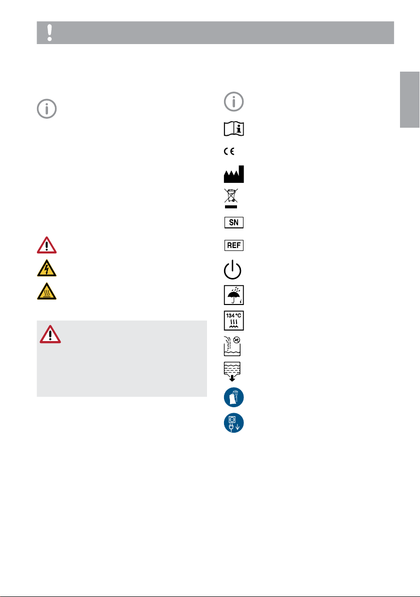
1�1 Warnings and symbols � � � � � � � � � � 3
1�2 Copyright information � � � � � � � � � � � 3
2 Safety � � � � � � � � � � � � � � � � � � � � � � � � � � � 4
2�1 Intended purpose � � � � � � � � � � � � � � 4
2�2 Intended use� � � � � � � � � � � � � � � � � � 4
2�3 Improper use � � � � � � � � � � � � � � � � � 4
2�4 General safety information� � � � � � � � 4
2�5 Applicable guidelines and
standards � � � � � � � � � � � � � � � � � � � � 4
2�6 Qualified personnel � � � � � � � � � � � � � 5
2�7 Protection from electric shock � � � � � 5
2�8 Only use genuine parts � � � � � � � � � � 5
2�9 Transport and packaging� � � � � � � � � 5
2�10 Disposal � � � � � � � � � � � � � � � � � � � � � 5
Product description
3 Overview� � � � � � � � � � � � � � � � � � � � � � � � � 6
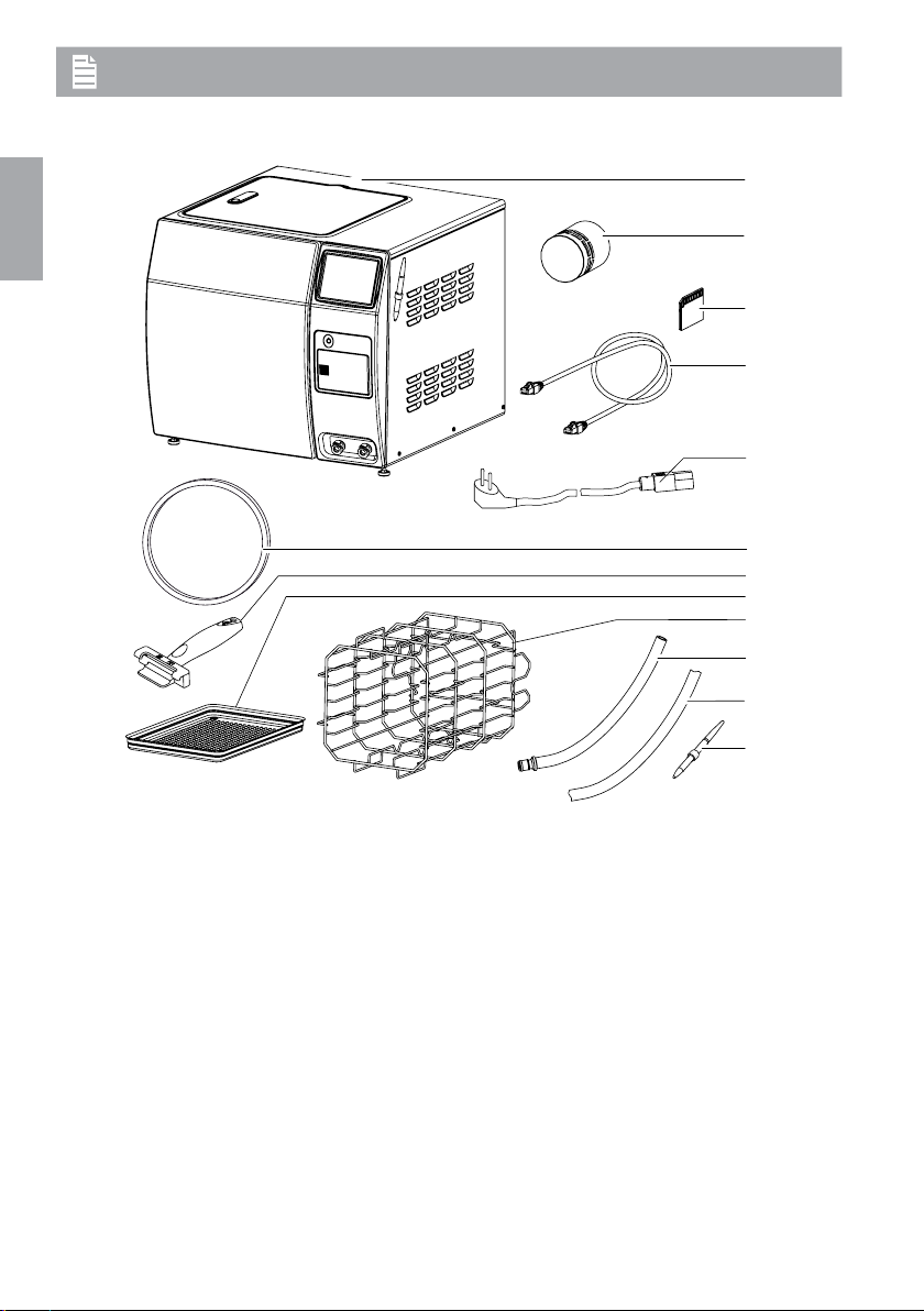
3�1 Scope of delivery � � � � � � � � � � � � � � 7
3�2 Accessories � � � � � � � � � � � � � � � � � � 7
3�3 Special accessories � � � � � � � � � � � � 7
3�4 Disposable materials � � � � � � � � � � � � 7
3�5 Wear parts and spare parts� � � � � � � 7
4 Technical data � � � � � � � � � � � � � � � � � � � � 8
4�1 Type plate � � � � � � � � � � � � � � � � � � � 10
4�2 Conformity assessment� � � � � � � � � 10
5 Operation � � � � � � � � � � � � � � � � � � � � � � � 11
5�1 Hygoclave 90 � � � � � � � � � � � � � � � � 11
5�2 Safety devices � � � � � � � � � � � � � � � 13
5�3 Overview of programs � � � � � � � � � � 15
5�4 Tyscor Pulse (optional) � � � � � � � � � 15
Installation
6 Requirements � � � � � � � � � � � � � � � � � � � � 17
6�1 Installation/setup room � � � � � � � � � 17

2 6046100064L02 1702V002SE
Contents
13�6 Preparations for steam
sterilisation � � � � � � � � � � � � � � � � � � 34
13�7 Loading the items for sterilisation
into the unit� � � � � � � � � � � � � � � � � � 36
13�8 Steam sterilising � � � � � � � � � � � � � � 37
13�9 Storing parts for sterilisation � � � � � 39
14 Documenting the sterilisation� � � � � � � � 40
14�1 Batch documentation � � � � � � � � � � 40
14�2 Automatic record output � � � � � � � � 41
14�3 Subsequent output of saved
records � � � � � � � � � � � � � � � � � � � � � 41
14�4 Printing out records� � � � � � � � � � � � 41
15 Messages on the touch screen � � � � � � 43
15�1 Note � � � � � � � � � � � � � � � � � � � � � � � 43
15�2 Information � � � � � � � � � � � � � � � � � � 43
16 Operating pauses � � � � � � � � � � � � � � � � � 45
16�1 Pause times � � � � � � � � � � � � � � � � � 45
17 Taking out of operation � � � � � � � � � � � � 45
17�1 Transport � � � � � � � � � � � � � � � � � � � 45
18 Restarting after an extended pause in
operation � � � � � � � � � � � � � � � � � � � � � � � 46
19 Maintenance� � � � � � � � � � � � � � � � � � � � � 47
19�1 Maintenance schedule � � � � � � � � � 47
19�2 Complete cleaning � � � � � � � � � � � � 48
19�3 Cleaning or replacing the door
seal � � � � � � � � � � � � � � � � � � � � � � � 50
19�4 Checking the hinge and oiling the
door spindle � � � � � � � � � � � � � � � � � 50
19�5 Clean or replacing water filters � � � 51
19�6 Changing the sterile air filter � � � � � 51
19�7 Function check � � � � � � � � � � � � � � � 52
Troubleshooting
20 Tips for operators and
service technicians� � � � � � � � � � � � � � � � 53
20�1 "Caution" messages � � � � � � � � � � � 53
20�2 "Fault" messages � � � � � � � � � � � � � 53
21 Emergency opening of the door� � � � � � 55
Appendix
22 Settings menu layout � � � � � � � � � � � � � � 56
EN

6046100064L02 1702V002SE 3
Other symbols
These symbols are used in the document and
on or in the unit:
Note, e�g� specific instructions regarding
efficient and cost-effective use of the unit�
Take note of the accompanying
documents�
0297 CE labelling with the number of the
notified body
Manufacturer
Dispose of correctly in accordance with
EU Directive 2012/19/EU (WEEE)�
Serial number
Order number
On/off switch
Monitor ambient conditions
Steam sterilise at 134 °C
Fresh water
Waste water
Wear hand protection�
Switch off and de-energise the device
(e�g� unplug from mains)�
1.2 Copyright information
All names of circuits, processes, names, soft-
ware programs and units used in this document
are protected by copyright�
The Installation and Operating Instructions must
not be copied or reprinted, neither in full nor in
part, without written authorisation from Dürr
Dental�
1 About this document
These installation and operating instructions
form part of the unit�
If the instructions and information in
these installation and operating instruc-
tions are not followed, Dürr Dental will
not be able to offer any warranty or as-
sume any liability for the safe operation
and the safe functioning of the unit�
1.1 Warnings and symbols
Warnings
The warnings in this document are intended to
draw your attention to possible injury to persons
or damage to machinery�
The following warning symbols are used:
General warning symbol
Warning – dangerous high voltage
Warning – hot surfaces
The warnings are structured as follows:
SIGNAL WORD
Description of the type and source of
danger
Here you will find the possible conse-
quences of ignoring the warning
iFollow these measures to avoid the
danger�
The signal word differentiates between four
levels of danger:
– DANGER
Immediate danger of severe injury or death
– WARNING
Possible danger of severe injury or death
– CAUTION
Risk of minor injuries
– NOTICE
Risk of extensive material/property damage
Important information
EN

4 6046100064L02 1702V002SE
Important information
NOTICE
Damage to the unit or to the items
being sterilised due to unsuitable
materials
iOnly sterilise instruments, packaging
and textiles that are suitable for steam
sterilisation according to the manufac-
turer's information�
2.4 General safety information
iWhen operating this device always observe all
guidelines, laws, and other rules and regula-
tions that are applicable at the site of opera-
tion�
iPrior to each use, check condition of the de-
vice and make sure it is in perfect working
order�
iDo not convert or modify the units�
iObserve the Installation and Operating
Instructions�
iMake the Installation and Operating Instruc-
tions available to the person operating the
device at all times�
2.5 Applicable guidelines and
standards
Guidelines
Medical Devices Directive
93/42/EEC Directive on Medical Devices� In its
current version�
Standards
In their current version�
DIN EN 13060
Small steam sterilisers�
EN 61010-1
Safety requirements for electrical equipment for
measurement, control and laboratory use�
EN 61010-2-040
Safety requirements for electrical equipment for
measurement, control and laboratory use – Part
2-040: Particular requirements for sterilisers and
washer-disinfectors used to treat medical mate-
rials�
EN 61326-1
Electrical equipment for measurement, control
and laboratory use – EMC requirements
2 Safety
Dürr Dental has designed and constructed this
device so that when used properly and for the
intended purpose there is no danger to people
or property� Nevertheless, residual risks can re-
main� You should therefore observe the follow-
ing notes�
2.1 Intended purpose
The Hygoclave is a small steam steriliser in ac-
cordance with DIN EN 13060 and is designed
for medical use�
2.2 Intended use
The programs offered by the steam steriliser en-
able the selection of 'type B' sterilisation cycles�
This means that it can be used to sterilise bulky
products, porous products and products with a
narrow lumen, packaged (single or multi-layer)
or unpackaged�
Before sterilising any medical devices, also refer
to the information provided by the manufactur-
ers of these medical devices (refer also to EN
ISO 17664)�
2.3 Improper use
Any other usage or usage beyond this scope is
deemed to be improper� The manufacturer ac-
cepts no liability for damages resulting from this�
In these cases the user/operator will bear the
sole risk�
WARNING
The sterilisation of liquids can cause
a risk of explosion, risk of burns,
boiling retardation and vapours that
are hazardous to health.
iDo not sterilise liquids in the unit�
WARNING
Risk of explosion due to ignition of
combustible materials
iDo not operate the unit in any rooms
in which inflammable mixtures may be
present, e�g� in operating theatres�
EN

6046100064L02 1702V002SE 5
Important information
2.10 Disposal
Unit
The unit may be contaminated� Instruct
the company disposing of the waste to
take the relevant safety precautions in
this case�
iDecontaminate potentially contaminated parts
before disposing of them�
iUncontaminated parts (e�g� electronics, plastic
and metal parts etc�) should be disposed of in
accordance with the local waste disposal reg-
ulations�
iIf you have any questions concerning the cor-
rect disposal of parts, please contact your
dental trade supplier�
Decontamination of potentially contaminated
parts
The following parts of the device may be con-
taminated�
– Sterilisation chamber
– Water container
– Water-carrying lines
In order to properly dispose of the potentially
contaminated parts, they must first be decon-
taminated� To do this, carry out the following
steps:
iEmpty the water containers�
iRemove all fixed connections for fresh water
and waste water�
iWipe-disinfect the inner surfaces of the water
containers with a surface disinfectant, e�g�
FD322 or FD333 from Dürr Dental�
iOnce the inner surfaces of the water contain-
ers have dried off, fill the fresh water container
with demineralized fresh water (see "7�7 Con-
necting the unit")�
iRun 2-3 cycles of the quick program�
iEmpty the water containers and wipe-disinfect
them�
2.6 Qualified personnel
Operation
Persons who operate the units must ensure safe
and correct handling based on their training and
knowledge�
iInstruct or have every user instructed in han-
dling the unit�
iRegularly train all operators who are responsi-
ble for use and maintenance of the device� As
part of this, the operators must also demon-
strate that they have understood everything
covered� Attendance lists of the training
course participants must also be kept�
Installation and repairs
iInstallation, readjustments, alterations, up-
grades and repairs must be carried out by
Dürr Dental or by qualified personnel specifi-
cally approved and authorized by Dürr Dental�
2.7 Protection from electric shock
iWhen working on the units observe all the
relevant electrical safety regulations�
iImmediately replace any damaged cables or
plugs�
2.8 Only use genuine parts
iOnly use Dürr Dental parts or accessories and
special accessories specifically approved by
Dürr Dental�
iOnly use only genuine working parts and
spare parts�
2.9 Transport and packaging
The original packaging provides optimum pro-
tection for the device during transport�
If required, original packaging for the unit can be
ordered from Dürr Dental�
Dürr Dental does not accept any respon-
sibility or liability for damage occurring
during transport due to the use of incor-
rect packaging, even where the unit is
still under guarantee�
iOnly transport the device in its original pack-
aging�
iKeep the packing materials out of the reach of
children�
EN

6 6046100064L02 1702V002SE
3 Overview
1
2
3
4
8
9
5
6
7
10
11
12
1 Steam steriliser Hygoclave 90
2 Sterile air filter
3 SD memory card
4 Network cable
5 Mains cable
6 Door seal
7 Tray handle
8 Tray
9 Carrier, rotatable, for 6 trays or 3 standard tray cassettes
10 Drain hose for waste water and fresh water
11 Water drain hose for "automatic water discharge"
12 Stylus with magnet bracket
Product description
EN

6046100064L02 1702V002SE 7
Product description
3.5 Wear parts and spare parts
The following working parts need to be changed
at regular intervals (refer to the "Maintenance"
section):
Sterile air filter � � � � � � � � � � � � � � � � 6046-000-14
Door seal � � � � � � � � � � � � � � � � � � � 6046100080
Tray handle � � � � � � � � � � � � � � � � � � 6046100102
Stylus with magnet bracket � � � � � � 6046100129
Water filter set� � � � � � � � � � � � � � � � 6046100132
Drain hose for manual emptying of
fresh and waste water on the fore side
of the device � � � � � � � � � � � � � � � � � 6046100105
Water drain hose for "automatic water
discharge" on the rear side of the de-
vice� � � � � � � � � � � � � � � � � � � � � � � � 6046100128
Lubricant � � � � � � � � � � � � � � � � � � � 9000474001
Information on spare parts can be found
on the website portal for authorised spe-
cialist dealers under:
www�duerrdental�net�
3.1 Scope of delivery
The following items are included in the scope of
delivery (possible variations due to country-spe-
cific requirements and/or import regulations):
Hygoclave 90 . . . . . . . . . . . . . . . . . . 6046-01
– Carrier for trays or standard tray cassettes
– Trays
– Tray handle
– SD memory card
– Stylus with magnet bracket
– Drain hose for manual emptying of fresh and
waste water on the fore side of the device
– Water drain hose for "automatic water dis-
charge" on the rear side of the device
– Water filter set
– Hexagon key for emergency unlocking
– Sterile air filter
– Hygotest, starter kit
– Network cable
– Mains cable
– Software "Tyscor Pulse"
– Installation and operating instructions
– Handover and installation record
3.2 Accessories
The following articles are necessary for the op-
eration of the unit, depending on the applica-
tion:
Tray (perforated) � � � � � � � � � � � � � � 6046100112
3.3 Special accessories
The following optional items can be used with
the device:
Hygoprint Plus
(label printer, network capable) � � � 6046100035
Labelling set for
Hygoprint Plus � � � � � � � � � � � � � � � 6046100130
Hygopure 90
(reverse osmosis system) � � � � � � � 6046100017
Hygodem 90 (ion exchanger)� � � � � 6046100114
3.4 Disposable materials
The following materials are consumed during
operation of the device and must be ordered
separately:
Hygotest (Helix test bodies
with test strips) � � � � � � � � � � � � � � � 6050-600-03
EN

8 6046100064L02 1702V002SE
Product description
4 Technical data
Electrical data for the unit
Nominal voltage V AC 230
Electrical frequency Hz 50
Rated power W2600
Standby consumption W 1
Fuses 2 x T 12 AH / 250 V~ (IEC 60127)
Over-voltage category II
General technical data of device
Dimensions (H x W x D) cm 48 x 57�5 x 54
Weight, empty kg 65
Other technical data
Heat output at 23°C MJ/h 6�5
Noise level * dB(A) <65
Operating mode Continuous operation
Capacity of fresh water container lapprox� 4
Capacity of waste water container lapprox� 4
Operating pressure (absolute) max� kPa 325
Operating pressure (absolute) min� kPa approx� 5
Response pressure (relative), safety valve bar 2�55
Water and dust protection (in acc� with
IEC 60529) IP 20
Degree of soiling (in accordance with EN
61010-1) 2
* In accordance with EN ISO 1680 Airborne Noise Emissions; measured in a sound-insulated room�
Technical data for the sterilisation chamber
Internal dimensions, useable volume (∅x
D) cm 26 x 35
Volume l19
Load capacity (unpackaged instruments)
Bulky hollow instruments
Porous materials
kg
kg
6
2
Sterilisation temperature in acc� with DIN
EN 13060 °C 134 + 3
Heat-up time, at room temperature min approx� 15
Sterilisation hold time, program-depend-
ent min 3�5 - 20�5
Drying time, program-dependent min 10�5 - 16
Classification
Medical Devices Directive (93/42/EEC)
Manufacturer: Dürr Dental
Class IIb
(based on rule 15)
EN

6046100064L02 1702V002SE 9
Product description
Electromagnetic compatibility (EMC)
High-frequency emissions in accordance
with CISPR11
Group 1
Class B
Mains impedance, in accordance with
IEC61000-3-11 Ω< 0�1
Harmonics in acc� with IEC61000-3-2 Not applicable
Voltage fluctuations/flickers in acc� with
IEC61000-3-3 Not applicable
Conducted high-frequency disturbance
variable V1in acc� with IEC61000-4-6 Veff 3
Emitted high-frequency disturbance varia-
ble E1in accordance with IEC61000-4-3 V/m 4
Internal memory
Memory capacity 10,000 cycles
Network connection
LAN technology Ethernet
Default IEEE 802�3u
Data rate Mbit/s 100
Connector RJ45
Type of connection Auto MDI-X
Cable type ≥CAT5
Ambient conditions during storage and transport
Temperature °C -10 to +60
Relative humidity %85
Ambient conditions during operation
Temperature °C +15 to +35
Relative humidity %< 85
Air pressure hPa 750 to 1060
Altitude above mean sea level m< 2000
Connection for "automatic fresh water supply connection"
Union nut "3/4
Screw-in connector "3/8
Running water pressure bar (kPa) 1�5 - 5�5 (150 - 550)
Drain hose
Hose length m1�50
EN

10 6046100064L02 1702V002SE
Product description
4.1 Type plate
The type plate is located on the rear of the unit�
4.2 Conformity assessment
This device has been subjected to conformity
acceptance testing in accordance with the cur-
rent relevant European Union guidelines� This
equipment conforms to all relevant require-
ments�
EN

6046100064L02 1702V002SE 11
Product description
1 Cover for waste water container and fresh
water container
2 Touch screen
3 On/off switch
4 SD memory card slot
5 Sterile air filter
6 Connection (quick release coupling) for
"manual waste water emptying"
7 Connection (quick release coupling) for
"manual fresh water emptying"
8 Condenser
9 Pressure gauge cover
10 Motor shaft cover
11 Electrical connections
12 Network connection
13 Connection for "automatic water drain"
14 Connection for "automatic fresh water sup-
ply connection"
15 Roller feet, for positioning of the unit
16 Sterilisation chamber
17 Door seal
18 Door spindle
19 Adjustable feet, for height adjustment of the
unit
The Hygoclave 90 small steam steriliser is used
to sterilise objects with steam at temperatures
of 121°C or 134°C under pressure�
The unit sterilises on the basis of the fractionat-
ed vacuum method� This ensures that the ob-
jects being sterilised are wetted or penetrated
with saturated steam� This method is suitable
for steam sterilisation of all loads that will be en-
countered in a medical practice�
The sterilisation chamber is protected against
overheating�
Use fresh distilled or demineralised water for
every sterilisation process�
Vacuum phase
A vacuum is generated in several phases de-
pending on the program�
Sterilisation phase
Saturated steam is generated inside the sterilis-
er chamber until the specified values are
reached� The actual sterilisation takes place
during the predefined hold time�
5 Operation
5.1 Hygoclave 90
1
2
3
4
5
11
12
13
14
15
8
10
9
SD
6
7
16
17
18
19
EN

12 6046100064L02 1702V002SE
Product description
Water container
MIN
MAX
1
1
2
1 Fresh water container
2 Waste water container
The unit is equipped with a fresh water contain-
er (left-hand side) and a waste water container
(right-hand side)� The maximum capacity of
each container is 4 litres�
Depending on the selected program and the
load, an average of approx� 7 sterilisation cycles
is possible�
The minimum and maximum fill levels are de-
tected via a water level sensor�
Fresh water supply
The supply with fresh water is provided either
via the internal fresh water container or via an
external water treatment system, which is con-
nected to the in-house water supply�
Only use high-quality distilled or demineralised
water� Guideline values for water quality in ac-
cordance with DINEN 13060 Appendix C�
If a water treatment system is connected there
is no need to fill up the fresh water container�
Waste water emptying
The waste water is collected in the waste water
container at the end of each cycle�
The waste water can be manually emptied or,
when connected to the central sewerage sys-
tem, drain off automatically�
Water treatment system
With the aid of a water treatment system it is
possible to produce water with optimum fresh
water quality for steam generation in the unit�
The water treatment system is connected to the
fresh water connection of the unit and to the in-
house water supply�
Drying phase
The parts for sterilisation in the sterilisation
chamber are dried under vacuum� Afterwards
the sterilisation chamber is vented via the sterile
air filter and the door can be opened�
Vacuum drying ensures optimum drying results
even when the parts for sterilisation are pack-
aged�
Sterilisation chamber
The capacity of the sterilisation chamber is 19 li-
tres� It can be filled with a load according to de-
mand�
The maximum load depends on the load type
and the selected program�
Steam generator and heating system
The device has a high-performance steam gen-
erator� This is coupled to an insulated heating
system (heat pipe), which fully encloses the
sterilisation chamber� This unique combination
ensures fast process times and very good dry-
ing results�
Steam condenser and vacuum pump
The combination of steam condenser and vacu-
um pump, which has been specially developed
for steam sterilisation, enables reliable and fast
generation of a deep vacuum in all phases of
the process�
The resulting high venting capacity ensures the
very good sterilisation and drying results�
Carrier, trays, standard tray cassettes
The carrier can be loaded with up to 6 trays or –
rotated through 90° – 3 standard tray cassettes�
EN

6046100064L02 1702V002SE 13
Product description
– printed out via a network printer
– forwarded to document creation software
5.2 Safety devices
The unit has several safety devices for protect-
ing the operator, patient and unit:
– Safety door latch
– Fresh water check
– Electronic parameter control
– Process evaluation system
– Safety valve
– Additional function check
If one or more of the parameter(s) exceed the
specified limit values, the unit outputs warnings
or fault messages and cancels the program if
necessary�
If the program is cancelled a message will be
displayed on the touch screen�
Safety door latch
The device continuously monitors the pressure
and temperature and will not allow the door to
be opened if overpressure is present in the steri-
lisation chamber� The automatic door latch en-
sures that the door only opens slowly (by rotat-
ing the door spindle)� Even in the case of pres-
sure differences, pressure equalisation takes
place until the door is fully opened�
Fresh water check
Each time the program is started an automatic
check of the fresh water is performed via an in-
tegrated conductivity measurement� This en-
sures that specified values are not exceeded�
Stains on instruments and contamination of the
unit are prevented (assuming careful instrument
preparation)�
Electronic parameter control
The device operates with electronic parameter
control� Values for pressure, temperature and
time are automatically monitored in the pro-
grams� This ensures that the total running time
of a program is optimised depending on the
load�
Process evaluation system
The process evaluation system monitors and
compares ACTUAL process parameters with
TARGET process parameters� In this way, faults
in the program sequence can be detected and
correct sterilisation results can be ensured�
Altitude
Adjustments for altitude (above mean sea
level) and therefore to the ambient pres-
sure are performed automatically�
Operating elements
1
2
1 Touch screen
2 On/off switch
The touch screen can be used to adjust settings
on the device and select programs� Instructions
can be entered on the touch screen either with
the tip of a finger or with a stylus�
Start screen on the touch screen
Batch documentation
The device has an internal memory in which all
data for completed cycles (> 10,000 cycles) is
saved�
In order to enable effective batch documenta-
tion and subsequent checking of completed
programs, the record can be saved immediately
after the end of the cycle and output at a later
time�
The record data can be further processed in
various ways:
– saved to an SD memory card
– saved to a network storage location
EN

14 6046100064L02 1702V002SE
Product description
Safety valve
A safety valve ensures pressure is released if the
pressure is higher than 2�6bar�
Additional function check
With the aid of test programs, it is possible to
perform additional function checks at any time:
– Check the device for leakages in the steam
system with the vacuum test
– Use the Bowie-Dick test to check that the
steam penetration of porous items for sterili-
sation (e�g� textiles) is sufficient�
EN

6046100064L02 1702V002SE 15
Product description
5.3 Overview of programs
Type tests Universal
program
Quick pro-
gram
Gentle
program
Prions
program
Programme type in accordance with EN
13060
Type B Type B Type B Type B
Dynamic pressure testing of the sterilisation
chamber
XXXX
Air leakage XXXX
Empty chamber test XXXX
Bulky load XXXX
Porous partial load X X X
Porous full load X X X
Hollow body B XXXX
Hollow body A XXXX
Single packaging XXXX
Multiple packaging X X X
Drying, bulky load XXXX
Drying, porous load X X X
Sterilising temperature 134°C 134°C 121°C 134°C
Steriliser pressure (absolute) 312�0 kPa 312�0 kPa 210�7 kPa 312�0 kPa
Hold time 5�5 min 5�5 min 20�5 min 20 min
Max� bulky load 10 kg 6 kg 6 kg 10 kg
Max� single weight (e�g� load on tray, stand-
ard tray cassettes)
3�3 kg 2 kg 2 kg 3�3 kg
Max� massive load in containers 10 kg 6 kg 10 kg
Max� single-packed, bulky load 6 kg 1�5 kg 6 kg 6 kg
Max� double-packed, bulky load 6 kg 6 kg 6 kg
Max� porous load 2 kg 2 kg 2 kg
Max� single-packed, porous load 2 kg 2 kg 2 kg
Max� double packed, porous load 2 kg 2 kg 2 kg
X = compliance with all applicable sections of standard DIN EN 13060
EN

16 6046100064L02 1702V002SE
Product description
5.4 Tyscor Pulse (optional)
The software is connected via the network to the units from Dürr Dental and displays the current sta-
tus as well as messages and errors�
All messages are logged and can be printed or sent�
Regular maintenance and upkeep is implemented in the tasks� Reminders signal when a task is due�
The cockpit shows the devices with the current characteristic data and provides a quick overview of
the functional status of the devices�
The software interface consists of the menu bar, the side bar and the contents area�
1
23
1 Menu bar
2 Side bar
3 Contents area
The contents area depends on the tab selected on the side bar� The current messages are always
displayed in the lower part of the contents area�
If there are several current messages, then the mouse wheel or the or buttons can be
used to scroll through the messages�
The views and rights depend on the selected access level (Operator, Administrator or Service
Technician)�
While the software is running (even if the software window is closed), the access level is visible in the
task bar (or Mac OS menu bar)� The symbol shows the current status of the devices (see "13�4 Moni-
toring the device with Tyscor Pulse")� If a new message appears, a speech bubble tip also appears�
EN

6046100064L02 1702V002SE 17
7 Installation
7.1 Carrying the unit
iThe unit must only be carried by two persons�
iUse suitable carrying aids if necessary�
2x
7.2 Remove the transport locks
iRemove the internal and external packaging
materials and transport protection�
7.3 Setting up the unit
The unit is intended for operation outside the
patient environment�
The following gaps/distances must be main-
tained:
– To the treatment chair: min� radius of 1�5m
– To the rear wall: at least 10cm
– To the sides: at least 5cm
– The unit should be freely accessible at the top
so that the installed fresh water container can
be filled and to ensure good ventilation�
10 cm
85
kg
6 Requirements
6.1 Installation/setup room
The room chosen for set up must fulfil the fol-
lowing requirements:
– Solid, horizontal ground/floor
– Closed, dry, dust-protected interior room�
Should not be a room made for another pur-
pose (e�g� boiler room or wet cell)
– Required distances between the unit and the
wall and to the side must be complied with
(see "7�3 Setting up the unit")�
– Room chosen for set-up must be well venti-
lated
– No flammable gases in the proximity of the
unit
– Observe the required ambient conditions
(see "4 Technical data")�
– Mains cable plug connections must be freely
accessible so they can be quickly disconnect-
ed if there is any danger�
Installation
EN

18 6046100064L02 1702V002SE
Installation
7.4 Removing the protective film
from the touch screen
iGrasp one corner of the protective touch
screen film and peel it off carefully�
7.5 Checking the SD memory card
After transport it is possible that the SD memory
card is no longer in the correct position�
iTo open the cover: briefly press on the
marked area�
iTake out the SD memory card and reinsert it:
press it in slightly, carefully pull it out and then
slide it back in until it clicks�
NOTICE
A build-up of heat can impair correct
operation of the unit.
This may result in a shortened service
life and extended cycle times�
iComply with the specified minimum
gaps/distances�
iDo not exceed the maximum permit-
ted ambient temperature�
CAUTION
Danger of burns from hot steam
In the event of a fault, the safety valve
on the rear of the unit is triggered by
overpressure, i�e� if the pressure is
above the normal operating pressure,
and hot steam is given off�
iInstall the unit in such a way that op-
erators are not put in any danger�
iPlace the unit on a horizontal table� The
load-bearing capacity of the table must be
suitable for the weight of the unit including op-
erating media and load (see "4 Technical
data")�
iAlign the unit in both planes so that it is hori-
zontal using the two front adjustable feet�
On the underside of the unit there are 2
adjustable feet at the front and 2 roller feet at
the rear, which are used for easier positioning
of the unit�
When adjusting the unit, make sure that it
is secured at all times so that it cannot fall
down, e�g� by getting somebody else to help�
The design of the internal sterilisation
chamber has a slope so that full con-
densate draining is ensured� For this
reason it is not necessary to set up
the unit with a tilt towards the rear�
EN
Other manuals for Hygoclave 90
1
Table of contents