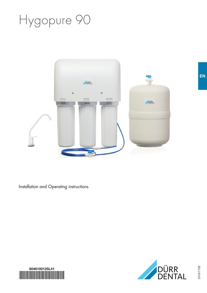
Durr Dental Hygowater User manual

EN
Hygowater
Operating Instructions
8500200016L01
*8500200016L01*
1904V001


Contents
Important information
1About this document .. . . . . . . . . . . . . 2
1.1 Warnings and symbols .. . . . . . . 2
1.2 Copyright information .. . . . . . . . 2
2 Safety .. . . . . . . . . . . . . . . . . . . . . . . . . 3
2.1 General notes .. . . . . . . . . . . . . . 3
2.2 Intended use .. . . . . . . . . . . . . . . 3
2.3 Improper use .. . . . . . . . . . . . . . . 3
2.4 Systems, connection with other
devices .. . . . . . . . . . . . . . . . . . . 4
2.5 General safety information .. . . . . 4
2.6 Specialist personnel .. . . . . . . . . 4
2.7 Electrical safety .. . . . . . . . . . . . . 4
2.8 Only use original parts .. . . . . . . . 5
2.9 Transport .. . . . . . . . . . . . . . . . . . 5
2.10 Disposal .. . . . . . . . . . . . . . . . . . 5
Product description
3Overview .. . . . . . . . . . . . . . . . . . . . . . . 6
3.1 Hygowater .. . . . . . . . . . . . . . . . . 6
3.2 Hygowater Booster .. . . . . . . . . . 6
3.3 Scope of delivery .. . . . . . . . . . . . 7
3.4 Accessories .. . . . . . . . . . . . . . . . 7
3.5 Optional accessories .. . . . . . . . . 7
3.6 Consumables .. . . . . . . . . . . . . . 7
4Technical data .. . . . . . . . . . . . . . . . . . . 8
4.1 Hygowater .. . . . . . . . . . . . . . . . . 8
4.2 Hygowater Booster .. . . . . . . . . . 10
4.3 Type plate .. . . . . . . . . . . . . . . . . 12
4.4 Evaluation of conformity .. . . . . . 12
5 Operation .. . . . . . . . . . . . . . . . . . . . . . 13
Usage
6Operation .. . . . . . . . . . . . . . . . . . . . . . 14
6.1 Basic handling .. . . . . . . . . . . . . . 14
6.2 Visual and acoustic signals .. . . . 15
6.3 Daily hygiene tasks .. . . . . . . . . . 16
6.4 Operation with Hygowater
Booster .. . . . . . . . . . . . . . . . . . . 16
7Self clean .. . . . . . . . . . . . . . . . . . . . . . 17
8Measuring the chlorine content .. . . . . 17
8.1 Evaluating the measurement
results .. . . . . . . . . . . . . . . . . . . . 19
9Replacing the pre-filter .. . . . . . . . . . . . 20
10 Replace the fuse .. . . . . . . . . . . . . . . . . 21
11 Cleaning of the outside surfaces .. . . . 22
12 Maintenance .. . . . . . . . . . . . . . . . . . . . 23
12.1 Hygowater .. . . . . . . . . . . . . . . . . 23
12.2 Hygowater Booster .. . . . . . . . . . 23
Troubleshooting
13 Tips for operators and service techni-
cians .. . . . . . . . . . . . . . . . . . . . . . . . . . 24
Contents
8500200016L01 1904V001 1
EN

Important information
1 About this document
These operating instructions form part of the unit.
If the instructions and information in these
operating instructions are not followed,
Dürr Dental will not be able to offer any
warranty or assume any liability for the
safe operation and the safe functioning of
the unit.
These operating instructions are what are known
as the "original operating instructions".
1.1 Warnings and symbols
Warnings
The warnings in this document are intended to
draw your attention to possible injury to persons
or damage to machinery.
The following warning symbols are used:
General warning symbol
Warning – dangerous high voltage
The warnings are structured as follows:
SIGNAL WORD
Description of the type and source of
danger
Here you will find the possible conse-
quences of ignoring the warning
❯Follow these measures to avoid the
danger.
The signal word differentiates between four levels
of danger:
–DANGER
Immediate danger of severe injury or death
–WARNING
Possible danger of severe injury or death
–CAUTION
Risk of minor injuries
–NOTICE
Risk of extensive material/property damage
Other symbols
These symbols are used in the document and on
or in the unit:
Note, e.g. specific instructions regarding
efficient and cost-effective use of the unit.
Refer to Operating Instructions.
Disconnect all power from the unit.
Refer to the accompanying electronic
documents.
CE labelling
Function indicator
OK button
Self clean
Reset button
Manufacturer
Serial number
Order number
Dispose of correctly in accordance with
EU Directive 2012/19/EU (WEEE).
1.2 Copyright information
All circuits, processes, names, software pro-
grams and units mentioned in this document are
protected by copyright.
The operating instructions must not be copied or
reprinted, neither in full nor in part, without writ-
ten authorisation from Dürr Dental.
Important information
2 8500200016L01 1904V001
EN

2 Safety
The unit has been developed and designed in
such a way that dangers are effectively ruled out
if used in accordance with the intended use.
Nevertheless, residual risks can remain.
You should therefore observe the following notes.
2.1 General notes
Observe the following notes to ensure safe and
effective operation:
❯Water generated by the Hygowater system is
not suitable for drinking.
❯Do not use the Hygowater system for more
than two dental treatment units unless the cor-
responding accessories have been installed.
The system's internal filter may get blocked
and the system may put a stop to operation.
❯The water system described in the following
should be kept short and straight. Piping with
blind ends and long pipes make the Hygowater
system less effective. The water can be con-
taminated again by a flow system with an
unfavourable design.
❯Make sure the filters (pre-filters/ultrafilters) are
serviced or replaced as required. The internal
filters need to be clean if the Hygowater sys-
tem is to work effectively. Hard water reduces
the efficiency of the disinfection process or
brings it to a standstill. The filters may become
blocked and cause damage to the electrolysis
chamber.
❯The recommended water pressure may not be
exceeded. The potential consequences of the
pressure exceeding 6 bars as stipulated are
burst pipes and flooding.
❯Verify that the effect is as it should be at regular
intervals. The chlorine content in the water from
the transmission instruments or cup filler must
be measured every week to ensure effective
operation. The chlorine content may fluctuate.
❯Do not use the Hygowater system with liquids
other than water or without filters. The unit is
designed to be used to disinfect processed
water in the dental treatment unit, with the
quality equivalent to that of drinking water.
Using the unit with liquids other than water
and/or without the correct filters will damage
the unit and make it less effective.
❯The unit must always be kept perfectly upright.
Do not try to operate the unit when it is on its
side or tilted, as water will leak out and poten-
tially cause damage to the unit or its surround-
ings.
❯The use of oxidative disinfectants, such as free
chlorine, can cause corrosion. The Hygowater
system operates with a low (0.2-1 mg/l) chlo-
rine content, but some materials are not at all
compatible with oxidative disinfectants. Make
sure that your dental treatment unit is suitable
for use with processed water of drinking water
quality in line with the WHO Guidelines for
Drinking-Water Quality and the limits set out by
the EU.
❯Use water from the Hygowater with caution.
Always read the label and product information
before use.
2.2 Intended use
The device produces active chlorine* for disinfec-
tion of Dental Unit Waterlines (DUWLs).
Spectrum of efficacy: Reduces water bacteria –
including Legionella.
* Active chlorine is generated from (sodium)
chloride by electrolysis, and is the designation
used by EU in regard to the Biocidal Products
Regulation.
2.3 Improper use
Any other usage or usage beyond this scope is
deemed to be improper. The manufacturer
accepts no liability for damages resulting from
this. In these cases the user/operator will bear
the sole risk.
❯Do not use the Hygowater system on dental
treatment units when other disinfection sys-
tems are switched on. This may stop the
Hygowater from working as effectively or at all.
WARNING
Risk of explosion due to ignition of
combustible materials
❯Do not operate the unit in any rooms in
which inflammable mixtures may be
present, e.g. in operating theatres.
Important information
8500200016L01 1904V001 3
EN

2.4 Systems, connection with
other devices
Additional devices connected with medical elec-
trical devices must be proven to conform with
their corresponding IEC or ISO standards. All
configurations must continue to comply with the
standard requirements for medical systems (see
IEC 60601-1).
Whoever connects additional devices to medical
electrical devices automatically becomes the sys-
tem configurator and is responsible for ensuring
that the system corresponds with the standard
requirements for systems. Local laws take priority
over the requirements outlined above.
2.5 General safety information
NOTICE
Danger to components due to electro-
static discharge (ESD)
❯Always switch off the operating voltage
before carrying out any assembly or
installation work on the device.
❯Before and during the installation or
assembly work on the device, always
ensure that the person carrying out the
work is earthed.
❯Always comply with the specifications of all
guidelines, laws, and other rules and regula-
tions applicable at the site of operation for the
operation of this unit.
❯Check the function and condition of the unit
prior to every use.
❯Do not convert or modify the unit.
❯Comply with the specifications of the Installa-
tion and Operating Instructions.
❯The Installation and Operating Instructions
must be accessible to all operators of the unit
at all times.
2.6 Specialist personnel
Operation
Unit operating personnel must ensure safe and
correct handling based on their training and
knowledge.
❯Instruct or have every user instructed in han-
dling the unit.
Installation and repairs
❯Installation, readjustments, alterations,
upgrades and repairs must be carried out by
Dürr Dental or by qualified personnel specifi-
cally approved and authorized by Dürr Dental.
2.7 Electrical safety
WARNING
Danger due to power surges
Contact with live parts can cause severe
or even fatal injuries.
❯In order to avoid the risk of power
surges, only ever connect this unit to a
mains power supply with protective
earthing.
The unit must only be opened by
authorised staff. If the unit is opened
(with the exception of removing the lid
to replace the pre-filter), there is a risk
of coming into contact with high volt-
age.
❯Comply with all the relevant electrical safety
regulations when working on the unit.
❯Never touch the patient and unshielded plug
connections on the unit at the same time.
❯Replace any damaged cables or plugs immedi-
ately.
❯It needs to be easy to get to the power outlet
supplying power to the unit.
Observe the EMC rules concerning medical
devices
❯The unit is intended for use in professional
healthcare facilities (in accordance with IEC
60601-1-2). If the appliance is operated in
another environment, potential effects on elec-
tromagnetic compatibility must be taken into
account.
❯Do not operate the unit in the vicinity of HF sur-
gical instruments or MRT equipment.
❯Maintain a minimum distance of at least 30 cm
between the unit and other electronic devices.
❯Keep a minimum distance of 30 cm between
the unit and mobile radio devices.
❯Note that cable lengths and cable extensions
have effects on electromagnetic compatibility.
Important information
4 8500200016L01 1904V001
EN

NOTICE
Negative effects on the EMC due to
non-authorised accessories
❯Use only Dürr Dental parts or acces-
sories specifically approved by Dürr
Dental.
❯Using any other accessories may result
in increased electromagnetic interfer-
ence emissions or the unit having
reduced electromagnetic immunity,
leading to an erroneous operation
mode.
NOTICE
Erroneous operation mode due to use
immediately adjacent to other devices
or with other stacked devices
❯Do not stack the unit together with
other devices.
❯If this is unavoidable, the unit and other
devices should be monitored in order
to ensure that they are working cor-
rectly.
NOTICE
Reduced performance characteristics
due to insufficient distance between
unit and portable HF communication
devices
❯Keep a distance of at least 30 cm
between the unit (including parts and
cables of the unit) and portable HF
communication devices (wireless units)
(including their accessories such as
antenna cables and external anten-
nas).
2.8 Only use original parts
❯Only use Dürr Dental parts or accessories and
special accessories specifically approved by
Dürr Dental.
❯Only use only original wear parts and replace-
ment parts.
2.9 Transport
The original packaging provides optimum protec-
tion for the unit during transportation.
If required, original packaging for the unit can be
ordered from Dürr Dental.
Dürr Dental will not accept any responsi-
bility or liability for damage occurring dur-
ing transportation due to the use of incor-
rect packaging, even where the unit is still
under guarantee.
❯Completely empty the unit before transporting
it.
❯Only transport the unit in its original packaging.
❯Keep the packing materials out of the reach of
children.
2.10 Disposal
Unit
The unit must be disposed of properly.
Within the European Union, the unit must
be disposed of in accordance with EU
Directive 2012/19/EU (WEEE).
❯If you have any questions about the correct
disposal of parts, please contact your dental
trade supplier.
Important information
8500200016L01 1904V001 5
EN

Product description
3 Overview
3.1 Hygowater
1
5
4
3
2
1 Housing
2 Lid
3 Cleaning button
4 OK button
5 Function indicator
9
10
86
7
6 Connection for water drain
7 Connection for fresh water supply connec-
tion
8 Fuse holder
9 230 V mains power supply
10 Reset button
3.2 Hygowater Booster
12
1 Housing
2 Lid
6
53
4
3 Connection for water drain
4 Connection for water supply connection
5 Fuse holder
6 230 V mains power supply
Product description
6 8500200016L01 1904V001
EN

3.3 Scope of delivery
The following items are included in the scope of
delivery (possible variations due to country-spe-
cific requirements and/or import regulations):
Hygowater water treatment unit
with free outlet .. . . . . . . . . . . . . . . 8500900050
– Water treatment unit
–Pre-filter
–Ultrafilter
– Chlorine test strips for Hygowater
– Mains cable
– Hygowater hose set
3.4 Accessories
The following items are required for operation of
the device, depending on the application:
Hygowater Booster .. . . . . . . . . . . . 8500900051
3.5 Optional accessories
The following optional items can be used with the
device:
Wall bracket for Hygowater .. . . . . . 8500200012
Wall bracket for Hygowater and
Hygowater Booster, central supply .. 8500200013
3.6 Consumables
The following materials are consumed during
operation of the device and must be ordered
separately:
Chlorine test strips for Hygowater .. 8500200000
Pre-filter for Hygowater .. . . . . . . . . 8500200001
Product description
8500200016L01 1904V001 7
EN

4 Technical data
4.1 Hygowater
Electrical data
Rated voltage V AC 110–230
Max. power consumption W 368
Fuses 2 AT for 230 V AC
Protection class II
Internal voltage supply 1 (electronic mod-
ule/valves) V DC 12
Internal power supply 1 (electronic mod-
ule/valves) A 5
Internal voltage supply 2 (electrodes) V 6–24
Internal power supply 2 (electrodes), up to A 4
General technical data
Dimensions (H x W x D) mm 452 x 166 x 430
Approximate weight (without pre-filter and
water)
kg
5
Approximate weight during operation kg 9
Ambient temperature °C 10–35
Inlet pressure bar 1.5–6
Outlet pressure bar 2.6–2.9
Water flow rate l/min 1.5–2
Classification
Medical Devices Directive (93/42/EEC) Class I
Adept Water Technologies A/S
Mileparken 22
DK-27430 Skovlunde
Denmark
Electromagnetic compatibility (EMC)
Interference emission measurements
High-frequency emissions in accordance with CISPR 11 Group 1
Class B
Interference voltage at the power supply connection
CISPR 11:2009+A1:2010 Compliant
Electromagnetic interference radiation
CISPR 11:2009+A1:2010 Compliant
Product description
8 8500200016L01 1904V001
EN

Electromagnetic compatibility (EMC)
Interference immunity measurements cover
Immunity to electrostatic discharge
IEC 61000-4-2:2008
± 8 kV contact
± 2 kV, ± 4 kV, ± 8 kV, ± 15 kV air
Compliant
Immunity to radio-frequency, electromagnetic fields
IEC 61000-4-3:2006+A1:2007+A2:2010
3 V/m
80 MHz–2.7 GHz
80% AM at 1 kHz
Compliant
Immunity to near fields of wireless HF communication
devices
IEC 61000-4-3:2006+A1:2007+A2:2010
See immunity to interference table, near fields of wireless
HF communication devices.
Compliant
Immunity to interference table, near fields of wireless HF communication devices
Radio service Frequency band
MHz
Test level
V/m
TETRA 400 380 - 390 27
GMRS 460
FRS 460 430 - 470 28
LTE band 13, 17 704 - 787 9
GSM 800/900
TETRA 800
iDEN 820
CDMA 850
LTE band 5
800 - 960 28
GSM 1800
CDMA 1900
GSM 1900
DECT
LTE band 1, 3, 4, 25
UMTS
1700 - 1990 28
Bluetooth
WLAN 802.11 b/g/n
RFID 2450
LTE band 7
2400 - 2570 28
WLAN 802.11 a/n 5100 - 5800 9
Electromagnetic compatibility (EMC)
Interference immunity measurements supply input
Immunity to electrical fast transients/bursts – AC mains
voltage
IEC 61000-4-4:2012
± 2 kV
100 kHz repetition rate
Compliant
Product description
8500200016L01 1904V001 9
EN

Electromagnetic compatibility (EMC)
Interference immunity measurements supply input
Immunity to surges, line-line
IEC 61000-4-5:2005
± 0.5 kV, ± 1 kV
Compliant
Immunity to surges, line-earth
IEC 61000-4-5:2005
± 0.5 kV, ± 1 kV, ± 2 kV
Compliant
Immunity to conducted disturbances, induced by radio-
frequency fields – AC mains voltage
IEC 61000-4-6:2013
3 V
0.15–80 MHz
6 V
ISM frequency bands
0.15–80 MHz
80% AM at 1 kHz
Compliant
Immunity to voltage dips, short interruptions and voltage
variations
IEC 61000-4-11:2004
Compliant
Electromagnetic compatibility (EMC)
Interference immunity measurements SIP/SOP
Immunity to electrostatic discharge
IEC 61000-4-2:2008
± 8 kV contact
± 2kV, ± 4 kV, ± 8 kV, ± 15 kV air
Compliant
Immunity to electrical fast transients/bursts – I/O,
SIP/SOP ports
IEC 61000-4-4:2012
± 1 kV
100 kHz repetition rate
Compliant
Immunity to conducted disturbances, induced by radio-
frequency fields – SIP/SOP ports
IEC 61000-4-6:2013
3 V
0.15–80 MHz
6 V
ISM frequency bands
0.15–80 MHz
80% AM at 1 kHz
Compliant
4.2 Hygowater Booster
Electrical data for the unit
Rated voltage V AC 110–230
Max. power consumption W 78
Fuses 2 AT for 230 V AC
Product description
10 8500200016L01 1904V001
EN

Electrical data for the unit
Protection class II
Internal voltage supply 1 (electronic mod-
ule/valves) V DC 12
Internal power supply 1 (electronic mod-
ule/valves) A 5
Internal voltage supply 2 (electrodes) V 6–24
Internal power supply 2 (electrodes), up to A 4
General technical data
Dimensions (H x W x D) mm 452 x 176 x 430
Approximate weight (without pre-filter and
water) kg 6
Approximate weight during operation kg 10
Ambient temperature °C 10–35
Outlet pressure bar 6
Water flow rate l/min 4
Product description
8500200016L01 1904V001 11
EN

4.3 Type plate
The type plate is located on the rear side of the
unit.
1 Type plate
4.4 Evaluation of conformity
This device has been subjected to conformity
acceptance testing in accordance with the cur-
rent relevant European Union guidelines. This
equipment conforms to all relevant requirements.
Product description
12 8500200016L01 1904V001
EN

5 Operation
1
2
3
1 Hygowater
2Ultrafilter
3Pre-filter
2
1
1 Hygowater Booster
2Ultrafilter
The processed water is pumped from the con-
nection for the fresh water supply connection
through the pre-filter and into a disinfection
chamber by a pump. In the pre-filter, particles are
filtered out and certain chemical compounds are
bonded by activated carbon. In the disinfection
chamber, the salts present in the processed
water are converted into chlorine by electrolysis.
The last remaining germs are eliminated in a spe-
cial reaction zone and a downstream ultrafilter fil-
ters the processed water once again before it
reaches the treatment unit.
In combination with the Hygowater Booster, it is
possible to treat water centrally to gain greater
volumes of softened, filtered and disinfected
water. Up to six treatment units can be supplied
with water.
The connection for the fresh water supply con-
nection in the Hygowater Booster is connected
up to the connection for the water drain in the
Hygowater. The processed water is filtered
through two ultrafilters in the Hygowater Booster
before it reaches the treatment unit.
The ultrafilter in the Hygowater/the two
ultrafilters in the Hygowater Booster is/are
replaced when the Customer Service
department performs the annual service.
There is no need for an ultrafilter in the
Hygowater if a Hygowater Booster is con-
nected.
Product description
8500200016L01 1904V001 13
EN

Usage
6 Operation
Operation of the unit is automated.
Once connected to the voltage and water supply,
the unit will supply water as and when the treat-
ment unit requires it.
The unit does need to be handled in order
for the cleaning mode to be activated and
for servicing to be performed.
6.1 Basic handling
User interface and display elements
1
2
3
4
1 Function indicator
2 OK button
3 Cleaning button
4 Reset button
Readiness for operation
The unit is switched on once it is connected to
the voltage supply. When the OK button is
flashing green or lit constantly, the unit is ready to
supply water.
When the function indicator is flashing, the
electrolysis process is underway.
Usage
14 8500200016L01 1904V001
EN

6.2 Visual and acoustic signals
The following table shows a number of possible visual and/or acoustic signals that may require some
action to be taken.
Signal Sound Cause/Action
OK button lights up green No sound The unit is ready for use.
Function indicator lights up No sound The electrolysis process is underway.
OK button flashes green No sound The water tank is being filled so there is tem-
porarily no water.
Wait until the water tank has been filled.
Cleaning button lights up
blue
No sound The cleaning mode has been activated and will
end automatically after 30 minutes.
Press the cleaning button to end the self-clean
process manually.
OK button lights up red Constant beeping Water is leaking out or there is a sensor fault
Disconnect the unit from the water supply and
pull out the mains plug.
OK button alternately flashes
red and green
Beeping at hourly
intervals
The pre-filter is completely worn.
Replace the pre-filter.
Usage
8500200016L01 1904V001 15
EN

6.3 Daily hygiene tasks
Follow the instructions provided by the
treatment unit manufacturer.
All treatment unit systems that carry water need
to be rinsed through at the start of the working
day. This reduces the bioaccumulation (biofilm)
that occurs during stagnation by some consider-
able margin.
As a way of preventing biofilm from building up,
the unit needs to be rinsed through even if it has
not been used on patients during a particular
working day.
❯Remove transmission instruments before rins-
ing through.
❯Rinse through all extraction points (transmis-
sion instruments, multifunctional syringes, ultra-
sonic handpieces, cup filler) for around
two minutes.
6.4 Operation with Hygowater
Booster
1 2
1 Hygowater
2 Hygowater Booster
When using the Hygowater Booster, up to six
treatment units can be supplied with water.
The connection for the water supply connection
in the Hygowater Booster is connected up to the
connection for the water drain in the Hygowater.
Installation, set-up and commissioning are per-
formed by Dürr Dental or by a person or com-
pany authorised to do so by Dürr Dental.
The two ultrafilters in the Hygowater
Booster are replaced when the Customer
Service department performs the annual
service.
Usage
16 8500200016L01 1904V001
EN

7 Self clean
If a treatment unit is not used for a relatively long
period of time, biofilm may build up in the water
pipes. In this case, more powerful disinfection is
required.
CAUTION
A higher concentration of chlorine is
added during the self-clean process.
The permitted limits can be exceeded
here.
There is a danger of repercussions on
patients' health.
❯After the self-clean process, the pipes
need to be rinsed through until the val-
ues are measured as being below the
permitted limits. Take measurements
using chlorine test strips.
❯Press the cleaning button .
The cleaning button lights up blue. The
cleaning mode will end automatically after
30 minutes.
❯There is also the option of pressing the
cleaning button again to cancel the cleaning
mode.
The cleaning button will no longer be lit up.
8 Measuring the chlorine
content
It is recommended that the concentration of free
chlorine is measured for one of the instruments
at least once a week. This measurement should
be taken using chlorine test strips immediately
after rinsing through is complete for the day.
Fill the measured values into a "Weekly
test" table in order to keep an eye on the
results. Contact the manufacturer for suit-
able templates.
üSuitable container with a capacity of at least
200 ml
üChlorine test strips
❯Drain at least 200 ml of water before taking a
sample of water.
❯Drain at least 50 ml of water from the instru-
ment into a clean beaker.
❯Remove a chlorine test strip from the container.
Usage
8500200016L01 1904V001 17
EN

❯Dip the chlorine test strip into the water and
move it around for around 30 seconds.
❯Fold the chlorine test strip in the middle and
compare the colour against the colour scheme
shown on the container for the chlorine test
strips.
❯Add the result to the "Weekly test" table along
with the date and unit number.
Usage
18 8500200016L01 1904V001
EN
Other manuals for Hygowater
2
Table of contents
Other Durr Dental Water Filtration System manuals
Popular Water Filtration System manuals by other brands

Streamline
Streamline FILTERPLUS INSTR-MINI-MAXI-RO instruction manual

Applied Membranes
Applied Membranes AAA-125P MANUAL FOR INSTALLATION, OPERATION AND MAINTENANCE

Philips
Philips WP3970/01 user manual

Panasonic
Panasonic ET-RFV200C operating instructions

Separ Filter
Separ Filter SWK-2000/40/WSA operating manual

GCTek
GCTek PondKeeper System instructions

JNS Aquaria
JNS Aquaria FR-S quick start guide

Axminster
Axminster Workshop AW15AFS Original instructions

Aquatec-Watermaker
Aquatec-Watermaker DD 500 user manual

CALEFFI
CALEFFI 577 Series manual

Nexus
Nexus EN-7P Operation manual

Cleveland
Cleveland SteamerGard WT-300 Installation, operation and maintanance manual