6 7
10092261 Rev. A 12/07
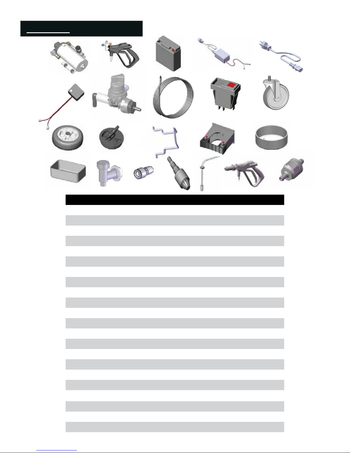
Part Number Description
1. 10092250 Pump Replacement Kit
2. 10091845 Spray Attachment
3. 10092253 Battery
4. 10092254 Battery Charger
5. 10092211 Cord, Battery Charger
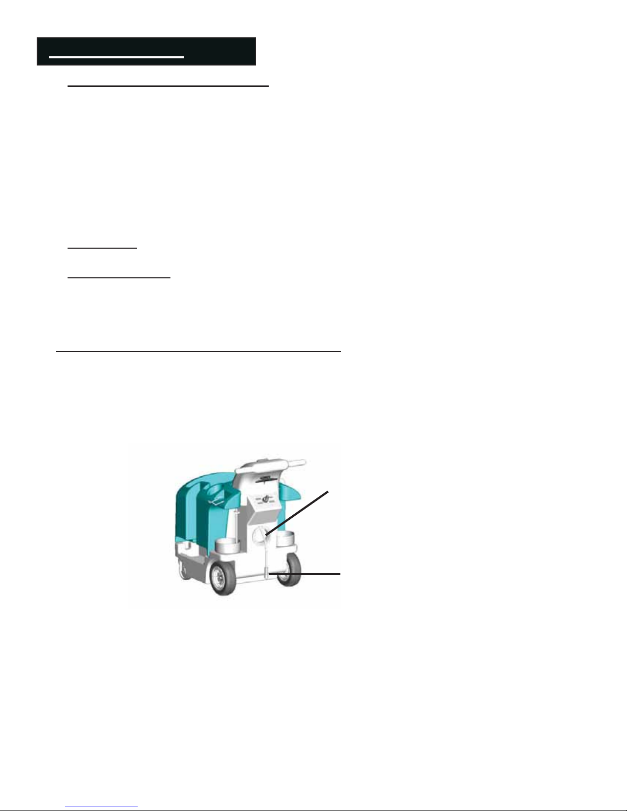
6. 10092255 Battery life indicator
7. 10092262 Chemical selector valve
8. 10091864 Discharge hose replacement, black
9. 10092252 On/off switch replacement kit
10. 10091867 Caster replacement kit (set of 2)
11. 10091866 Wheel replacement kit (set of 2)
12. 10091861 Fill port cap
13. 10092217 Sign hanger
14. 10092258 Mop clips (set of 2)
15. 10092256 Bottle holder (round) - (set of 2)
16. 10092257 Bottle holder (rectangular) - (set of 2)
17. 90084615 Tap style drain
18. 690014 Metering tip kit
19. 10076302 Foot valve, EPDM
20. 10092251 Chemical feed line kit
21. 10092259 Optional foaming attachment
22. 10069255 Check Valve
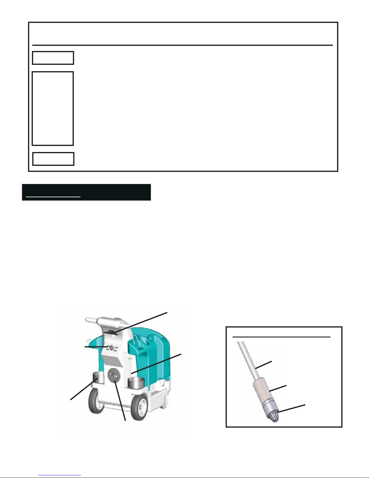
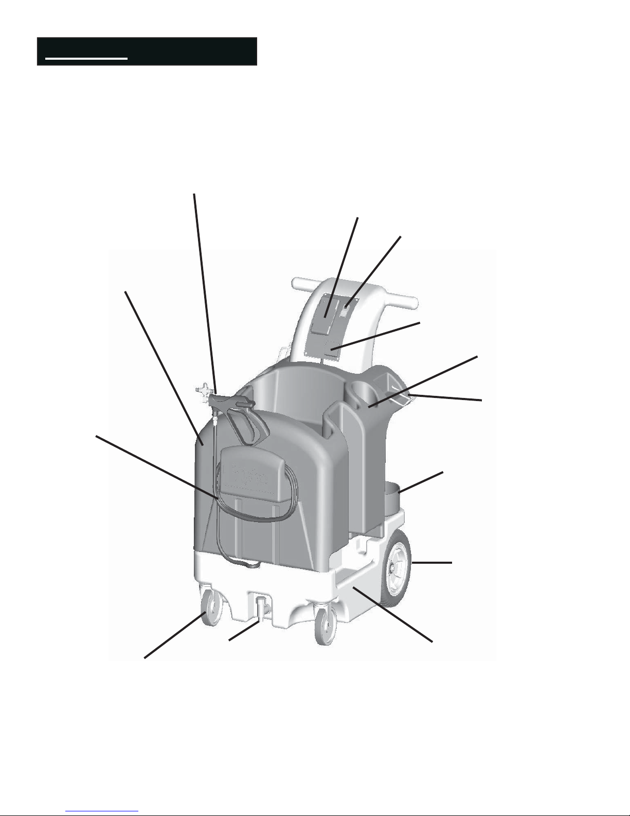
1. 2. 3. 4. 5.
7. 9.
6. 10.
11. 12. 13.
8.
14. 15.
16. 17. 18. 19. 20. 21.
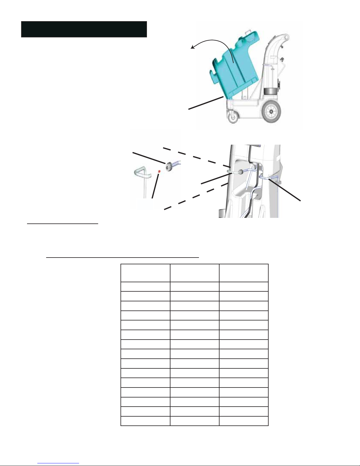
Parts List
22.
Ref. Part N. Description Quantity
1 H10092250 Pump Replacement Kit 1
2 H10091845 Spray Attachment 1
3 H10092253 Battery 1
4 H10092254 Battery Charger 1
5 H10092211 Cord, Battery Charger 1
6 H10092255 Battery life indicator 1
7 H10092262 Chemical selector valve 1
8 H10091864 Discharge hose replacement, black 1
9 H10092252 On/off switch replacement kit 1
10 H10091867 Caster replacement kit 2
11 H10091866 Wheel replacement kit 2
12 H10091861 Fill port cap 1
13 H10092217 Sign hanger 1
14 H10092258 Mop clips 2
15 H10092256 Bottle holder (round) 2
16 H10092257 Bottle holder (rectangular) 2
17 H90084615 Tap style drain 1
18 H690014 Metering tip kit 1
19 H10076302 Foot valve, EPDM 1
20 H10092251 Chemical feed line kit 1
21 H10092259 Optional foaming attachment 1
22 H10069255 Check Valve 1
10092261 Rev. A 12/07
Part Number Description
1. 10092250 Pump Replacement Kit
2. 10091845 Spray Attachment
3. 10092253 Battery
4. 10092254 Battery Charger
5. 10092211 Cord, Battery Charger
6. 10092255 Battery life indicator
7. 10092262 Chemical selector valve
8. 10091864 Discharge hose replacement, black
9. 10092252 On/off switch replacement kit
10. 10091867 Caster replacement kit (set of 2)
11. 10091866 Wheel replacement kit (set of 2)
12. 10091861 Fill port cap
13. 10092217 Sign hanger
14. 10092258 Mop clips (set of 2)
15. 10092256 Bottle holder (round) - (set of 2)
16. 10092257 Bottle holder (rectangular) - (set of 2)
17. 90084615 Tap style drain
18. 690014 Metering tip kit
19. 10076302 Foot valve, EPDM
20. 10092251 Chemical feed line kit
21. 10092259 Optional foaming attachment
22. 10069255 Check Valve
1. 2. 3. 4. 5.
7. 9.
6. 10.
11. 12. 13.
8.
14. 15.
16. 17. 18. 19. 20. 21.
Parts List