Dustbane Hurricane 400 XTT User manual

Operations Manual
Hurricane
Automatic Scrubber
Serial #:_________________________ Date of Purchase:_________________________
More info : www.dustbane.ca
02-2011
400 XTT
400 XTT - Traction 510 XTT
510 XTT - Traction
610 XTT 670 XTT 670 Eco
400 Eco

1.Index
1. Index 1
2. General Information 2
2.1. Scope of the manual 2
2.2. Identifying the machine 2
2.3. Documentation provided with the machine 2
3. Technical Information 3
3.1. General description 3
3.2. Legend 3
3.3. Danger zones 4
4. Safety Information 4
4.1. Safety regulations 4
5. Handling And Installation 6
5.1. Lifting and transporting the packaged machine 6
5.2. Checks on delivery 6
5.3. Unpacking 6
5.4. Power supply batteries 6
5.4.1. Batteries: preparation 6
5.4.2. Batteries: installation and connection 7
5.4.3. Batteries: removal 8
5.5. Battery charger 8
5.5.1. Choosing the battery charger 8
5.6. Lifting and transporting the machine 8
6. Practical Guide For The Operator 9
6.1. Controls - Description 9
6.2. Mounting and adjusting the squeegee 11
6.3. Moving the machine when not in operation 11
6.4. Mounting and changing the brush/drive disks 12
6.5. Detergents – Instructions 12
6.6. Preparing the machine for work 13
6.7. Working 13
6.8. Some useful tips to get the most from your autoscrubber 15
6.8.1. Prewashing using brushes or pads 15
6.8.2. Drying 15
6.9. Draining the dirty water 15
6.10. Draining the clean water 17
7. Periods Of Inactivity 17
8. Battery Maintenance And Charging 17
9. Maintenance Instructions 17
9.1. Maintenance - General rules 17
9.2. Routine maintenance 18
9.2.1 Suction motor air lter and oat switch: cleaning 18
9.2.2 Basket lter: cleaning 18
9.2.3 Detergent lter: cleaning 18
9.2.4 Squeegee blades: replacing 19
9.2.5 Fuses: replacement 20
9.3. Routine maintenance 20
9.3. 1. Daily operations 20
9.3.2. Weekly operations 21
9.3.3. Six month operations 21
10. Troubleshooting 21
10.1. How to resolve possible problems 21

2
2. General Information
Read this manual carefully before carrying out any work on the machine.
2.1. Scope of the manual
This manual has been written by the Manufacturer and is an integral part of the machine. It denes
the purpose for which the machine has been designed and constructed and contains all the information
required by operators.
In addition to this manual containing all user information, other publications are available providing specic
information for maintenance personnel.
Constant respect for the instructions guarantees the safety of the operator and the machine, low running costs
and high quality results and extends the working life of the machine. Failure to respect the instructions may
lead to damage to the operator, machine, oor and environment.
Parts of the text requiring special attention are highlighted in bold and preceded by the symbols illustrated
and described below:
In line with the company’s policy of constant product development and updating, the Manufacturer reserves
the right to make modications without warning. Although your machine may dier appreciably from
the illustrations in this document, safety and the information contained in this manual are guaranteed.
2.2. Identifying the machine
• Information on the unit name and serial number can be found under the solution tank.
2.3. Documentation provided with the machine
• Operations Manual
• Quick User Guide
• Parts List
• Warranty Information
Indicates the need for attention in order to avoid a series of consequences that could cause
death or damage to the health of the operator.
Danger
Important
Indicates the need for attention in order to avoid a series of consequences that could cause
damage to the machine or work environment or nancial loss.
Indicates particularly important instructions.
Information

3
3. Technical Information
3.1. General description
This machine is an automatic scrubber for sweeping, washing and drying at, horizontal, smooth or moderately
rough, even and obstacle free oors in civil and industrial premises.
The automatic scrubber spreads a solution of water and detergent in the correct concentration on the oor and
then scrubs it to remove the dirt. By carefully choosing the detergent and brushes / pads from the wide range
of accessories available, the machine can be adapted to a wide range of combinations of types of oor and dirt.
A suction system incorporated in the machine dries the oor after washing by means of the low pressure
generated in the dirty water drum by the suction motor. The squeegee connected to the recovery tank collects
the dirty water.
The machine is moved forward by:
Non-Traction drive: the auto scrubber is provided with a special mechanical drive device which exploits
the friction between the brush and the oor to generate a forward movement (for further details, see
paragraph 6.7).
Traction drive: the auto scrubber is moved forward by means of a special electromechanical drive device.
3.2. Legend
Fig./Abb.
图
1
Fig./Abb./
图
2
Fig./Abb./
图
3
Fig./Abb./
图
4 Fig./Abb./
图
5
The main parts of the machine are as follows:
1. Control panel
2. Recovery tank – collects the dirty water picked up from the oor after washing [Ref. 2]
3. Head lift pedal – raises the brush head during transport [Ref. 3]
4. Head assembly – holds the brushes / pads [Ref. 4]
5. Brushes / pads – distribute the chemical solution on the oor and removes the dirt [Ref. 5]
6. Squeegee assembly – wipes and dries the oor by collecting the water [Ref. 6]
7. Solution tank – contains and transports the mixture of clean water and chemical solution [Ref. 7]

4
3.3. Danger zones
Tank assembly: when using certain detergents, danger of irritation for eyes, skin, mucous membranes
and respiratory tract and of asphyxia. Danger represented by the dirt collected from the environment
(germs and chemical substances). Danger of crushing between the two tanks when the recovery tank
is replaced on the solution tank.
Control panel: danger of short circuit.
Bottom of washing head: danger due to brush rotation.
Rear wheels: danger of crushing between the wheel and chassis.
Battery compartment (in the solution tank): danger of short circuit between the battery poles
and presence of hydrogen during charging.
4. Safety Information
4.1. Safety regulations
Read the Operations Manual carefully before start-up and use or before performing
maintenance or any other work on the machine.
Important
Rigorously respect all instructions in the Manual (in particular those relating to danger
and important information) and on the safety plates tted to the machine.The Manufacturer
declines all liability for damage to people or things resulting from failure to observe
the instructions.
• The auto scrubber must be used exclusively by persons trained in its use and/or who have
demonstrated their ability and have been expressly instructed to use the auto scrubber.
• The machine must not be used by minors.
• The machine must not be used for purposes other than those for which it was expressly designed.
Scrupulously respect all safety standards and conditions applicable to the type of building in which
the machine is to be operated (e.g.: pharmaceutical companies, hospitals, chemicals, etc).
• Do not use the machine in places with inadequate lighting or explosive atmospheres, on public
roads, in the presence of dirt hazardous to health (dust, gas, etc) and in unsuitable environments.
• The machine is designed for temperatures of between +4°C and +35°C when in use and between
+0°C and +50°C when not in use.
• The machine is designed to work in a humidity of between 30% and 95%.
• Never use or pick up ammable liquids or explosives (e.g. petrol, fuel oil, etc), ammable gases, dry
dusts, acids and solvents (e.g. paint solvents, acetone etc) even if diluted.
• Never pick up aming or incandescent objects.
• Never use the machine on slopes or ramps of more than 2%. In the case of slight slopes, do not use
the machine transversally, always maneuver with care and do not reverse.
• When transporting the machine on steeper ramps or slopes, take the utmost care to avoid tipping
up and/or uncontrolled acceleration. Move the machine on ramps and/or steps only with the brush
head and squeegee raised.
• Never park the machine on a slope.
• The machine must never be left unattended with the motor or engine on. Before leaving it, turn
the motor or engine o, make sure it cannot move accidentally.
• Always pay attention to other people, children in particular, present in the place where you are working.

5
• Never use the machine to transport people or things or to tow things. Do not tow the machine.
• Never rest objects of any weight on the machine for any reason.
• Never obstruct ventilation and heat dispersion slits.
• Never remove, modify or circumvent safety devices.
• Numerous unpleasant experiences have shown that a wide range of personal objects may cause
serious accidents. Before beginning work, remove jewelry, watches, ties, etc.
• The operator must always use personal protection devices - protective apron or overalls, non-slip
waterproof shoes, rubber gloves, protective goggles and ear protectors and mask to protect the
respiratory tract.
• Keep hands away from moving parts.
• Never use detergents other than those specied. Follow the instructions on the MSDS if you come
into contact.
• Make sure the power sockets used for the models with battery charger are connected to a suitable
grounding system and protected by dierential thermal solenoid switches.
• Make sure the electrical characteristics of the machine (voltage, frequency, absorbed power) given
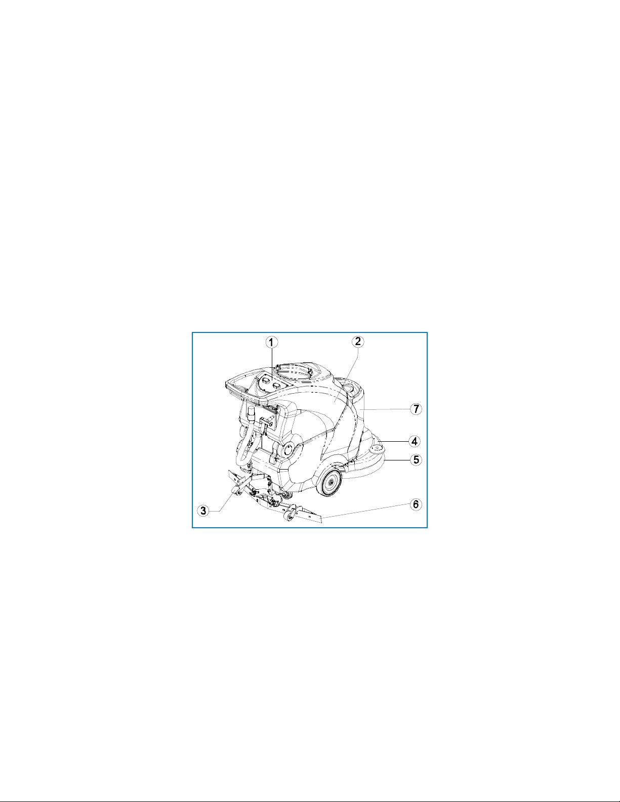
on the rating plate (g. 1) are the same as those of the main electricity supply. The machine with cable
has a three-wire cable and a three pin grounded plug for use in an appropriate grounded socket. The
ground wire is yellow and green. Never connect this wire to anything other than
the ground contact of the socket.
• It is crucial to respect the battery manufacturer’s instructions and current legislation.
The batteries should always be kept clean and dry to avoid surface leakage current. Protect
the batteries from impurities such as metal dust.
• Never rest tools on the batteries as this could cause short circuit and explosion.
• When using battery acid, always follow the relative safety instructions scrupulously.
• In the presence of particularly strong magnetic elds, assess the possible eect on the control
electronics.
• Never wash the machine with water jets.
• The uids collected contain detergent, disinfectant, water and organic and inorganic material.
They must be disposed o in accordance with local legislation.
• In the case of malfunction and/or faulty operation, turn the machine o immediately (disconnecting
it from the main power supply or batteries) and do not tamper. Contact a service center authorized
by the Manufacturer.
• All maintenance operations must be performed in an adequately lit place and only after
disconnecting the machine from the power supply.
• All work on the electrical system and all maintenance and repair operations other than those explicitly
described in this manual must be performed by specialized personnel expert in the sector only.
• If the power cable, plug or terminals require replacing, make sure the electrical connections and cable
grip inside the control panel are tightly fastened to guarantee the resistance of the cable if pulled.
Then replace the panel carefully to guarantee the safety of the operator.
• Only original accessories and spare parts supplied by the Manufacturer may be used in order
to guarantee safe problem-free operation of the machine. Never use parts removed from other
machines or from other kits.
• This machine has been designed and constructed to provide ten years’service from the fabrication
date shown on the rating plate (g. 1). After this time, whether the machine has been used or not,
it should be disposed of according to current legislation in the country in which it is used:
• At the end of the machine’s life, please dispose according to local regulations.

6
5. Handling And Installation
Important
During all lifting operations, make sure the packaged machine is rmly anchored to avoid
it tipping up or being accidentally dropped. Always load/unload trucks in adequately
lit areas.
5.1. Lifting and transporting the packaged machine
The machine, packaged on a wooden pallet by the Manufacturer, must be loaded using suitable equipment
onto the transporting vehicle. At destination, it must be unloaded using similar means.
A fork lift truck must always be used to lift the packaged body of the machine. Handle with care to avoid
knocking or overturning the machine.
5.2. Checks on delivery
When the carrier delivers the machine, make sure the packaging and machine are both whole and undamaged.
If the machine is damaged, make sure the carrier is aware of the damage and before accepting the goods,
reserve the right (in writing) to request compensation for the damage.
5.3. Unpacking
Important
When unpacking the machine, the operator must be provided with the necessary personal
protection devices (gloves, goggles, etc) to limit the risk of accident.
Unpack the machine as follows:
• Cut and remove the plastic straps;
• Remove the cardboard;
• Remove the bags in the battery compartment (in the detergent tank) and check the contents:
• product literature;
• battery bridges with terminals;
• 1 battery charger connector ;
• Depending on the model, remove the metal brackets or cut the plastic straps xing the machine
chassis to the pallet;
• Using a sloping ramp, push the machine backwards o the pallet;
• Unpack the brushes and squeegee
• Clean the outside of the machine in respect of safety regulations;
• After unpacking the machine, install the batteries. See relevant sections in this manual.
• The packaging may be kept as it can be reused to protect the machine if it is moved to another site
or to a repair workshop. Otherwise it must be disposed o in compliance with local legislation.
5.4. Power supply batteries
Two dierent types of battery may be installed on these machines: Deep Cycle and AGM
5.4.1. Batteries: preparation
The machines are set up at the factory based on the battery package selected. The default
setting on the machines is for Deep Cycle (Lead-Acid) batteries.
Information
The batteries are normally supplied lled with acid and ready for use. If the batteries are dry, before mounting
them on the machine, proceed as follows:

7
While installing or performing maintenance on the batteries, the operator must be provided
with the necessary personal protection devices (gloves, goggles, overalls, etc) to limit the
risk of accident. Keep away from open ames, avoid short circuiting the battery poles, avoid
sparks and do not smoke.
Danger
1. Remove the caps and ll all elements with specic sulphuric acid solution until the plates are entirely
covered (this requires at least a couple of passes for each element);
2. Leave for 4-5 hours to allow the air bubbles to come to the surface and the plates to absorb the electrolyte;
3. Make sure the level of electrolyte is still above the plates and if necessary top up with sulphuric acid solution;
Do not overll!
4. Close the caps;
5. Mount the batteries on the machine (following the procedure described below).
6. Before starting up the machine for the rst time, charge the batteries. Follow the instructions
in the relevant section.
5.4.2. Batteries: installation and connection
Check that all switches on the control panel are in the “0” (o) position. Make sure you
connect the terminals marked with a “+” to the positive poles of the battery. Do not check
the battery charge by sparking. Follow the instructions given below meticulously as short
circuiting the batteries could cause them to explode.
Danger
1. Make sure the two tanks are empty (if necessary, empty them. See the relevant paragraph).
2. Release the recovery tank (ref. 1) from the solution tank by pulling the catch. Tilt the recovery tank all the
way back to provide access to the battery compartment.
Fig./Abb.
图
1
Fig./Abb./
图
2
Fig./Abb./
图
3
Fig./Abb./
图
4 Fig./Abb./
图
5
3. Place the batteries in the compartment in the direction shown in the drawing printed inside
the compartment on the solution tank.
Important
Mount the batteries on the machine using lifting means suitable for their weight.
The positive and negative poles have dierent diameters.
4. Referring to the wiring layout, connect the battery cable and bridge terminals to the battery poles. Arrange
the cables as shown in the diagram, tighten the terminals on the poles and cover with Vaseline.
5. Lower the recovery tank. Make sure it latches properly with the solution tank;

8
5.4.3. Batteries: removal
When removing the batteries, the operator must be equipped with suitable personal
protection devices (gloves, goggles, overalls, safety shoes, etc) to reduce the risk of accidents.
Make sure the switches on the control panel are in the “0” position (o) and the machine
is turned o. Keep away from open ames, do not short circuit the battery poles, do not
cause sparks and do not smoke.
Danger
Proceed as follows:
1. Disconnect the battery wiring and bridge terminals from the battery poles.
2. If necessary, remove the devices xing the battery to the base of the machine.
3. Lift the batteries from the compartment using suitable lifting equipment.
5.5. Battery charger
Important
Never allow the batteries to become excessively at as this could damage them irreparably.
5.5.1. Choosing the battery charger
Specic chargers are required for optimal performance of both Deep Cycle (Lead-Acid) and AGM batteries.
Consult Dustbane literature/distributor to determine which charger is best. Refer to charger literature for more
information.
5.6. Lifting and transporting the machine
Important
All phases must be performed in an adequately lit room and adopting the safety measures
most appropriate to the situation. The operator must always use personal protection devices.
To load the machine onto a means of transport, proceed as follows:
1. Empty the recovery tank and solution tank;
2. Remove the squeegee and brushes / pads;
3. Remove the batteries;
4. Place the machine on the pallet and x it with plastic straps or metal brackets;
5. Lift the pallet (with the machine) using a fork lift truck and load it onto the means of transport;
6. Anchor the machine to the means of transport with cables connected to the pallet and machine itself.

9
6. Practical Guide For The Operator
6.1. Controls - Description
Fig./Abb./ 图 6
CT40
-
CT70
C
only
CT40 R – CT70 R
CT40 B -CT70 B CT40 C -CT70 C
CT40 BT -CT70 BT CT90 BT
CT40 BT50 MICRO SCRUB / ECS CT70 MICRO SCRUB / ECS
CT40 BT60 MICRO SCRUB / ECS
Fig./Abb./ 图 6
CT40
-
CT70
C
only
CT40 R – CT70 R
CT40 B -CT70 B CT40 C -CT70 C
CT40 BT -CT70 BT CT90 BT
CT40 BT50 MICRO SCRUB / ECS CT70 MICRO SCRUB / ECS
CT40 BT60 MICRO SCRUB / ECS
Fig./Abb./ 图 6
CT40
-
CT70
C
only
CT40 R – CT70 R
CT40 B -CT70 B CT40 C -CT70 C
CT40 BT -CT70 BT CT90 BT
CT40 BT50 MICRO SCRUB / ECS CT70 MICRO SCRUB / ECS
CT40 BT60 MICRO SCRUB / ECS
Fig./Abb./ 图 6
CT40
-
CT70
C
only
CT40 R – CT70 R
CT40 B -CT70 B CT40 C -CT70 C
CT40 BT -CT70 BT CT90 BT
CT40 BT50 MICRO SCRUB / ECS CT70 MICRO SCRUB / ECS
CT40 BT60 MICRO SCRUB / ECS
Fig./Abb./ 图 6
CT40
-
CT70
C
only
CT40 R – CT70 R
CT40 B -CT70 B CT40 C -CT70 C
CT40 BT -CT70 BT CT90 BT
CT40 BT50 MICRO SCRUB / ECS CT70 MICRO SCRUB / ECS
CT40 BT60 MICRO SCRUB / ECS
Hurricane - All units
Hurricane - 400 XTT
Hurricane - 400 Eco Hurricane - 670 Eco
Hurricane - 400 XTT Traction
Hurricane - 510 XTT Traction
Hurricane - 610 XTT
Hurricane - 670 XTT
Control Unit / Diagram # Information
Battery
charge light
All units / #1 Green LED on: batteries 100% to 50% charged;
Yellow LED on: batteries 50% to 18% charged;
Red LED on: batteries almost at.
Red LED ashing: batteries completely at; after a few seconds the brushes
Stop and the brush switch light also comes on.
Main key switch
– emergency
button
400 XTT Traction / #15
400 Eco / #15
510 XTT Traction / #15
610 XTT / #15
670 XTT / #15
670 Eco / #15
Enables and disables power to all machine functions. Acts as a safety device. To start
up the machine, turn the key clockwise. To stop the machine press the button.
Brush button
with light
All units / #3 Enables (LED on) or disables (LED O ) the “Brush” function.
400 Eco / 670 Eco: As well as enabling brush operation, pressing this button a)
automatically attaches the brushes and b) holding this button down for at least 5
seconds also selects the type of machine operation, “MICROFIBRE” with microbre disk
or “BRUSH-PAD” with brush/abrasive disk.

10
Suction button
with light
All units / #2 Switches the suction motor responsible for drying the oor being washed on (“LED
on”) or o (“LED o”). The light is on when there is power to the suction motor.
Tap lever All units except
670 Eco / #6
Provides continuous control of the ow of detergent to the Brushes.
Pull up to increase the liquid outow.
Detergent ow
regulation button
670 Eco / #20 Enables the ow of detergent to the brushes to be regulated constantly. The quantity
of liquid delivered is indicated by the LEDs
Drive lever All units / #7 Moves the machine forwards and rotates the brushes.
Squeegee lever All units / #8 Raises (when lifted) or lowers (when pushed down) the squeegee.
Direction
adjustment knob
All units / #10 Turn to correct any deviation of the machine from a straight line.
Head lowering /
raising pedal
All units / #9 On the left side of the machine, when pressed it lowers/raises the brush head.
Solution tank
level indicator
All units / #5 The LED comes on to indicate insucient water in the detergent tank.
Recovery tank
level indicator
All units / #4 When the dirty water drum is full the LED comes on and after a few seconds the
suction motor shuts down.
Direction
selection button
400 XTT Traction / #13
400 Eco / #13
510 XTT Traction / #13
610 XTT / #13
670 XTT / #13
670 Eco / #13
Sets movement of the machine to forwards or reverse
Speed control
potentiometer
400 XTT Traction / #11
400 Eco / #11
510 XTT Traction / #11
610 XTT / #11
670 XTT / #11
670 Eco / #11
Turning the potentiometer sets the machine speed.
Brush pressure
light
400 Eco / #17
670 Eco / #17
1 green LED on: minimum pressure;
2 green LEDs on: medium pressure;
3 green LEDs on: maximum permitted pressure;
3 green LEDs + 1 red LED on: excessive microbre pressure. The light is accompanied
by a beep.
Brush pressure
variation / brush-
microbre release
button
670 Eco / #19 Button with dual function:
1) Pressing the button briey modies the pressure of the brushes/microbre on the
surface to be cleaned.
2) When the brush and suction motor commands are disabled (o ) and the button is
held down for at least 5 seconds, the machine performs the automatic brush release
maneuver.

11
6.2. Mounting and adjusting the squeegee
Fig./Abb./
图
7
Fig./Abb./
图
9 Fig./Abb./
图
8
Fig./Abb./
图
10 Fig./Abb./
图
11
1
3
2
4
5
To mount the squeegee on the machine, proceed as follows:
1. Check that the squeegee mount (ref. 2) is raised, otherwise lift it by means of the squeegee lever (ref. 5);
2. Insert the suction hose sleeve (ref. 4) fully into the squeegee;
3. Slacken the two knobs (ref. 3) at the centre of the squeegee;
4. Insert the two threaded pins into the slots on the support (ref. 2);
5. Fix the squeegee by tightening the two knobs (ref. 3).
The squeegee blades scrape the lm of water and detergent from the oor and prepare the way for perfect
drying. With time, the constant rubbing makes the edge of the blade in contact with the oor rounded and
cracked, reducing the drying eciency and requiring it to be replaced. The state of wear should be checked
frequently.
For perfect drying, the squeegee must be adjusted in such a way that the edge of the rear blade bends during
operation by about 45° with respect to the oor at every point. Adjust the angle of the blade during operation
by regulating the height of the two wheels positioned behind the squeegee (ref. 1).
6.3. Moving the machine when not in operation
To move the machine, proceed as follows:
1. Raise the squeegee;
2. Push the head pedal down then to the right to raise the head;
3. Move the machine as follows:
Non-traction units: push or pull;
Traction units: to move the machine forwards, press the button/selector and then operate the drive lever.
To move the machine backwards, press the button/selector again then operate the drive lever. Speed can
be varied by the potentiometer knob.
Important
Do not leave the machine unattended or parked with the head lifted or the key inserted
in the emergency button.
4. Once you have reached your destination, lower the head by pressing the release pedal down and to the left,
then release it.
Important
Never work without the brushes and pads perfectly installed.

12
6.4. Mounting and changing the brush/drive disks
Function Units Information
Fitting the
brush / pad
400 XTT
400 XTT Traction
400 Eco
510 XTT
510 XTT Traction
610 XTT
Rest the brush on the oor in front of the machine and center it with the
guard. Lower the head and repeatedly action the brush/drive control lever
until the brush automatically engages on the ange hub. If the maneuver
is not successful, press on the handle again and repeat the centering and
repeated actioning of the brush/drive lever.
Removing
brush / pad
400 XTT
400 XTT Traction
400 Eco
510 XTT
510 XTT Traction
610 XTT
Raise the machine head by pushing the head lift pedal down and then to
the right and repeatedly action the brush/drive lever. After a few pulses, the
brush/es (or drive disk) is released and falls to the ground.
Automatic
brush / pad
attachment
670 Eco Place the disks under the head, making sure they rest against the stops to
align them with the attachment device, then press the brush button (ref. 3).
The machine performs the automatic attachment maneuver.
Automatic
brush / pad
release
670 Eco Turn o all devices (brushes, suction motor), then hold the brush / microbre
release button down for at least 5 seconds. The machine performs the
automatic brush release maneuver.
Fitting the
brushes / pads
670 XTT
*** MAKE SURE
MACHINE IS OFF
Place the brushes under the head drive disk. Lift the right brush with your
hands and turn it clockwise, locking it in position on the drive disk. Lift the left
brush with your hands and turn it counter-clockwise, locking it in position on
the drive disk. Use of abrasive disks: t the abrasive disk on the drive disk and
perform the operations described for tting the brush on the scrubber drier.
Removing
brushes / pads
670 XTT
*** MAKE SURE
MACHINE IS OFF
Raise the machine head by pushing the head lift pedal down and then to the
right. Turn the right brush counter-clockwise, releasing it from the drive disk.
Turn the left brush clockwise, releasing it from the drive disk.
6.5. Detergents – Instructions
Important
Always dilute the detergent according to the manufacturer’s instructions. Do not use bleach
or other oxidants, particularly in strong concentrations. Do not use solvents or hydrocarbons.
The temperature of the water and detergent must not exceed the maximum indicated
in the technical specication. They must be free of sand and/or other impurities.
The machine has been designed for use with low-foam biodegradable detergents made specically
for automatic scrubbers. For a complete and up-to-date list of the detergents and chemicals available, contact
the manufacturer. Use products suitable for the oor and dirt to be removed only. Follow the safety regulations
on use of detergents given in the section “Safety regulations”.

13
6.6. Preparing the machine for work
Important
Before starting work, wear overalls, ear protectors, non-slip waterproof shoes, mask
to protect the respiratory tract, gloves and all other personal protection devices
recommended by the supplier of the detergent used or necessitated by the work
environment.
Before starting work, proceed as follows:
1. Check the battery charge (recharge if necessary);
2. Lower the head;
3. Make sure the recovery tank is empty. If necessary, empty it;
4. Check that the tap lever is in the “CLOSED” position;
5. Fill the solution tank with a suitable concentration of clean water and low-foam detergent. Leave at
least 5 cm between the surface of the liquid and the opening of the tank;
6. If the machine is tted with the optional CHEM DOSE accessory, remove the cap and ll the tank with
appropriately diluted low-foam detergent.
7. Mount the most suitable brushes / pads for the oor and work to be performed;
8. Make sure the squeegee is rmly attached and connected to the suction hose. Make sure the back
blade is not worn.
If you are using the machine for the rst time, we recommend trying it on a large obstacle-
free surface rst to acquire the necessary familiarity. Always empty the dirty water drum
before lling the detergent tank again.
Information
For eective cleaning and to extend the working life of the machine, follow a few simple rules:
• Prepare the work area by removing all possible obstacles;
• Begin working from the furthermost point to avoid walking on the area you have just cleaned;
• Choose the straightest possible working routes;
• Divide large oors into parallel rectangular sections.
• If necessary, nish o by passing a mop or rag rapidly over parts inaccessible to the autoscrubber.
6.7. Working
After setting up the machine, proceed as follows:
1. Connect the machine as follows:
2. Move the tap lever (except 670 Eco) to the minimum detergent ow position. The detergent solution
starts owing to the brush;
3. Lower the squeegee by means of the corresponding lever;
4. Press the brush switch. For Eco machines, select the most suitable operating mode (BRUSH-PAD
mode with brush/abrasive disk or “MICROFIBRE” model with microbre disk) by holding the brush
switch down for at least 5 seconds;
5. Press the suction switch to start the suction motor;
6. Press the brush/drive lever;
Non-traction units:
• When the brush switch is in the “1” position and the drive lever is pulled, the motor which turns the brush
and moves the machine starts up. A special mechanical drive device uses the friction between the brush
and oor to generate a forward movement. When the mechanical drive lever is released, the brush motor
shuts down and the machine stops. If the machine pulls to one side, restore a straight course by using the
direction regulation knob. If the machine pulls to the right, turn the knob clockwise and vice versa.

14
Traction units:
• To move forwards or backwards, see paragraph 6.3.
In both traction and non-traction units:
• Periodically check that the detergent is reaching the brushes / pads and rell when it runs out. When
there is no longer sucient water in the detergent tank, the level indicator lights up. Stop and ll the
tank;
• If the machine is tted with the optional CHEM DOSE accessory, press the button to turn the device
on, then adjust the detergent mixture to send to the brushes using the regulation screw found on the
front of the CHEM DOSE. The quantity can be adjusted from 0.5% to 3% per litre of water.
• During work check the cleaning quality and adjust the detergent ow to the brushes /pads by raising
or lowering the lever as required. When using the 400 Eco, the ow control lever must be completely
lowered (valve closed). When using the 670 Eco model, adjust the detergent ow by pressing the
button. The quantity of detergent delivered is indicated by the LEDs.
Pressure of the brush / microbre on the surface to the cleaned:
400 Eco: During work make sure the pressure of the microbre on the work surface is within the permitted
operating range. If the 3 green LEDs and the red LED come on during operation, brush pressure must be
reduced by turning the knob (ref. A). Turning it clockwise increases the pressure of the brushes on the work
surface, turning it counter-clockwise reduces the pressure of the brushes on the work surface. To access the
knob, lift the recovery tank.
Fig./Abb./
图
12
Fig./Abb./
图
13 Fig./Abb./
图
14
Fig./Abb./
图
15
A
670 Eco: Pressing the pad pressure button briey modies the pressure of the brushes / microbre on the
surface to be cleaned. The pressure exerted is indicated by the LEDs.
Important
Empty the recovery tank each time you ll the solution tank. Never leave the suction motor
on and detergent tap open when parked.
• When the recovery tank is full, the level indicator comes on and after a few seconds the suction motor
shuts o. You must stop working and empty the tank. To restart the suction motor, turn the suction
switch o and then on again.

15
At the end of work:
• Place the tap lever (except 400 Eco & 670 Eco) in the“CLOSED” position;
• Release the brush/drive lever located under the handgrip. This turns the brush/drive motor o and
the machine stops;
• Stop the brush / pad;
• Lift the lever to raise the squeegee from the oor to prevent the continuous pressure from warping
the blades;
• Let the suction motor run for at least 2 minutes to make sure it is completely dry, then press “0”
on the suction switch to switch o the suction motor;
• Remove the brushes (or drive pads) to prevent them from warping permanently;
• Press the button to turn the optional CHEM DOSE accessory o;
• Depending on the model, disconnect the ANDERSON connectors;
• Empty and clean the dirty recovery tank.
6.8. Some useful tips to get the most from your autoscrubber
In the event of particularly stubborn dirt on the oor, washing and drying can be performed in two separate
operations.
6.8.1. Prewashing using brushes or pads
1. Adjust the detergent ow, except 400 / 670 Eco machines;
2. Place the brush switch in position“1”;
3. Lower the head;
4. Operate the drive lever to rotate the brushes;
5. Make sure the suction motor is o and the squeegee is raised;
6. Begin washing.
The ow of water must be adjusted in proportion to the desired advance speed. The slower the machine
moves forwards, the less water is needed. Persist when washing particularly dirty points to give the detergent
time to perform its mechanical action, detaching and suspending the dirt, and the brushes time to exert an
eective mechanical action.
6.8.2. Drying
Lower the squeegee and with the suction motor on, pass over the same area washed previously. The result is
equivalent to in-depth washing and subsequent ordinary maintenance will take less time.
To wash and dry at the same time, operate the brush, water, squeegee and suction motor simultaneously.
6.9. Draining the dirty water
Use suitable personal protection devices. Drain the dirty water with the machine
disconnected from the power supply.
Danger
The dirty recovery tank drain hose is at the back left side of the machine.
To empty the tank:

16
Fig./Abb./
图
7
Fig./Abb./
图
9 Fig./Abb./
图
8
Fig./Abb./
图
10 Fig./Abb./
图
11
1
3
2
4
5
1. Move the machine near a drain;
2. Detach the drain hose (ref. 2) from its seat by holding it near the xing spring (ref. 3) and pulling horizontally;
3. Keeping the hose end as high as possible, unscrew and remove the cap (ref. 4);
4. Lower the hose end gradually, controlling the intensity of the ow of water by adjusting the height
from the ground;
5. Check the amount of dirt left in the dirty water drum and if necessary wash it out. To facilitate cleaning
and complete emptying of the drum, you are recommended to unfasten and lift it;
6. When the dirty water has been totally drained, lower the dirty water drum (if previously lifted) and refasten
to the detergent tank;
7. Close the drain hose (ref. 2) by replacing the cap (ref. 4), check that it is tightly closed and replace
the hose in its housing.
Important
When washing the recovery tank, never remove the suction lter (ref. 2 below) from
its housing and never direct the jet of water against the lter itself.
Fig./Abb./
图
7
Fig./Abb./
图
9 Fig./Abb./
图
8
Fig./Abb./
图
10 Fig./Abb./
图
11
1
3
2
4
5

17
6.10. Draining the clean water
Use suitable personal protection devices. Drain the water with the machine disconnected
from the power supply.
Danger
To empty the tank:
1. Move the machine near a drain;
2. Unclip the drain hose from the lower right hand backside of the machine;
3. When the solution tank is completely empty, replace the cap.
The water and detergent solution can also be used to wash the recovery tank or software.
Information
7. Periods Of Inactivity
If the machine is not used for some time, remove the squeegee and brushes / pads, wash them and put them
away in a dry place (preferably in a bag or wrapped in plastic lm) away from dust. Park the machine with
the head lowered. Make sure the tanks are completely empty and perfectly clean.
Disconnect the machine from the power supply (disconnect the ANDERSON connector from the battery
wiring).
Batteries: Completely recharge the batteries before storing them. During long periods of inactivity, you should
charge the batteries regularly (at least once every two months) to keep them constantly at maximum charge.
8. Battery Maintenance And Charging
See appropriate Dustbane literature for specics on battery maintenance and charging.
9. Maintenance Instructions
Never perform any maintenance operations without rst disconnecting the batteries.
Maintenance on the electrical circuit and all other operations not explicitly described
in this manual must be performed by specialised personnel only, in compliance with current
safety legislation and as described in the maintenance manual.
Danger
9.1. Maintenance - General rules
Performing regular maintenance according to the Manufacturer’s instructions improves performance
and extends the working life of the machine. When cleaning the machine, respect the following:
• Avoid the use of high pressure washers. Water could penetrate the electrical compartment or motors
leading to damage or the risk of short circuit;
• Do not use steam to avoid the heat warping plastic parts;
• Do not use hydrocarbons or solvents as they could damage the cowling and rubber parts.

18
9.2. Routine maintenance
9.2.1 Suction motor air lter and oat switch: cleaning
Fig./Abb./
图
7
Fig./Abb./
图
9 Fig./Abb./
图
8
Fig./Abb./
图
10 Fig./Abb./
图
11
1
3
2
4
5
1. Unscrew and remove the tank cap (ref. 1) from the dirty water drum (ref. 4);
2. Make sure the dirty water drum (g. 10, ref. 4) is empty;
Clean the oat switch (ref. 5) at the back of the dirty water drum, taking care not to direct the water jet directly
against the oat switch;
3. Remove the suction motor air lter (ref. 2) from the oat switch support (ref. 3) inside the dirty water drum
at the top;
4. Clean the lter with running water or the detergent solution used on the machine;
5. Dry the lter thoroughly before replacing it in the support. Make sure the lter is correctly located
in its housing;
6. Screw the cap back on the dirty water drum.
9.2.2 Basket lter: cleaning
1. Remove the basket lter from the water ll hole at the front of the machine;
2. Clean the lter with running water or the detergent solution used on the machine;
3. Replace the lter back in its housing, making sure it is correctly positioned.
9.2.3 Detergent lter: cleaning
Fig./Abb./
图
7
Fig./Abb./
图
9 Fig./Abb./
图
8
Fig./Abb./
图
10 Fig./Abb./
图
11
1
3
2
4
5
1. Unscrew the screw located below the bottom tank (ref. 1);
2. Unscrew the detergent lter (ref. 2);
3. Clean the lter with running water or the detergent solution used on the machine;
4. Replace the lter back in its housing, making sure it is correctly positioned and retighten the screw.

19
9.2.4 Squeegee blades: replacing
The squeegee blades collect the lm of water and detergent from the oor and prepare the way for perfect
drying. With time, the constant rubbing leaves the edge of the blade in contact with the oor rounded and
cracked, reducing the drying eciency and requiring it to be replaced.
Turning or replacing the squeegee blades:
Fig./Abb./ 图 12
Fig./Abb./ 图 13 Fig./Abb./ 图 14
Fig./Abb./ 图 15
A
1. Lower the squeegee by using the squeegee lever;
2. Remove the squeegee from its mount by completely unscrewing the two knobs;
3. Remove the suction hose sleeve from the squeegee;
4. Release the catch (ref. 3 or 6);
5. Remove the two blade retainers (ref. 2 or 7) by rst pushing them towards the body of the squeegee (ref.1)
then extracting them;
6. Remove the blade (ref. 4 or 5);
7. Reuse the same blade by reversing the edge in contact with the oor until all four edges are worn out,
or replace with a new blade, tting it onto the screws on the body of the squeegee (ref. 1);
8. Reposition the two blade retainers (ref. 2 or 7) by centering the widest part of the slots over the xing
screws on the squeegee body (ref. 1), then pushing the blade retainers inwards;
9. Refasten the catch (ref. 3 or 6).
10. Replace the squeegee in its support following the instructions in paragraph 6.2.
Other manuals for Hurricane 400 XTT
1
This manual suits for next models
7
Table of contents
Other Dustbane Floor Machine manuals

Dustbane
Dustbane Integra TX 19914 User manual

Dustbane
Dustbane Gladiator 1280 User manual

Dustbane
Dustbane POWER CLEAN 1000 XT User manual

Dustbane
Dustbane Integra TX SS User manual

Dustbane
Dustbane Hurricane 890 XTT User manual

Dustbane
Dustbane Integra-D 19936 User manual

Dustbane
Dustbane 19315 User manual

Dustbane
Dustbane Floor cleaner User manual

Dustbane
Dustbane Hurricane 700 XTT User manual

Dustbane
Dustbane Power Clean Mini Spotter User manual