Dustcontrol TPR 50 Installation instructions

serial no:
TPR 50, 30 kW
instruktion
user instruction
Betriebsanleitung
gebruikers handleiding
manuel d’instruction
betjeningsvejledning
Part No 9050

TPR 50, 30 kW - 2 Part No 9050
Dustcontrol reserves the right to change specifications without notice and is under no obligation to alter pre-
viously delivered products. Dustcontrol is not responsible for errors or omissions in this catalogue.
Dustcontrol reserverar sig för tryckfel och produktförändringar.
Keine Gewähr für Druckfehler. Produktänderungen vorbehalten.
Tillverkare/Manufactured by/Hersteller/
Fabrikant/Fabriqué par:
Dustcontrol AB
Box 3088, Kumla Gårdsväg 14
SE-145 03 Norsborg
Tel: + 46 8 531 940 00
Fax: + 46 8 531 703 05
www.dustcontrol.com
Såld av/Sold by/Verkauft von/Verkocht door/
Vendu par:
Dustcontrol is niet aansprakelijk voor drukfouten in deze gebruikers handleiding of voor tussentijdse wi-
jzigingen. Dustcontrol behoudt zich het recht voor de specificaties van haar machines te wijzigen zonder
voorafgaande aankondiging en is niet verplicht reeds geleverde machines hierop aan te passen. Uitvoering en
leveringsomvang kunnen plaatselijk afwijken.
Dustcontrol se réserve le droit de modifier les spécifications sans indication préalable et sans aucune obligation
de changer les produits déjà livrés. Dustcontrol n’est pas responsable des erreurs et omissions faites dans ce
livret.
Dustcontrol forbeholder sig ret til at ændre specifikationerne uden forudgående varsel og er ikke forpligtet til
ændring af tidligere leverede produkter. Dustcontrol er ikke ansvarlig for trykfejl etc. i denne manual.

TPR 50, 30 kW - 3 Part No 9050
Innehållsförteckning
Säkerhetsföreskrifter ___________ 5
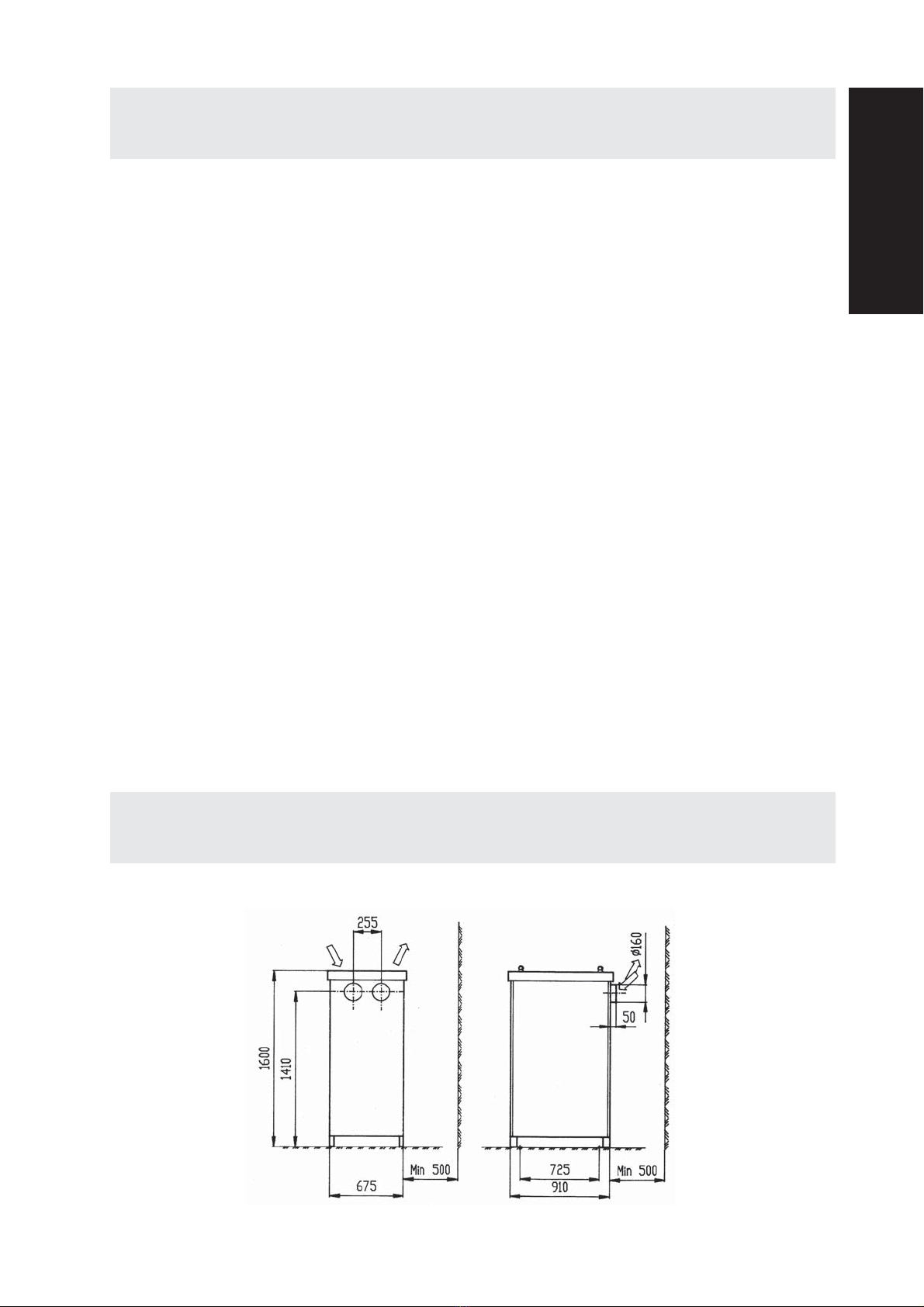
Mått och uppställning __________ 5
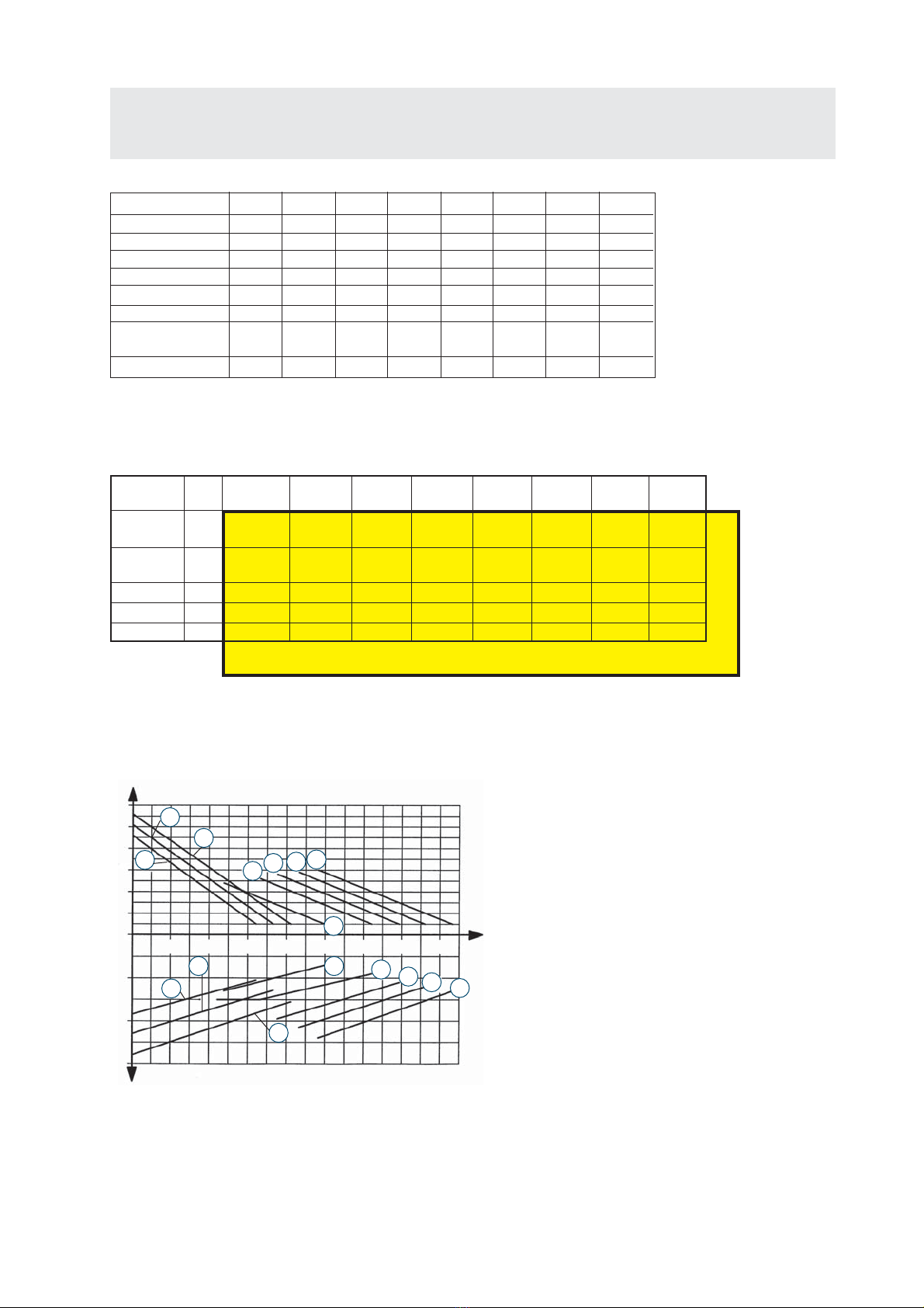
Tekniska data _________________ 6
Funktionsbeskrivning___________ 7
Installation ___________________ 8
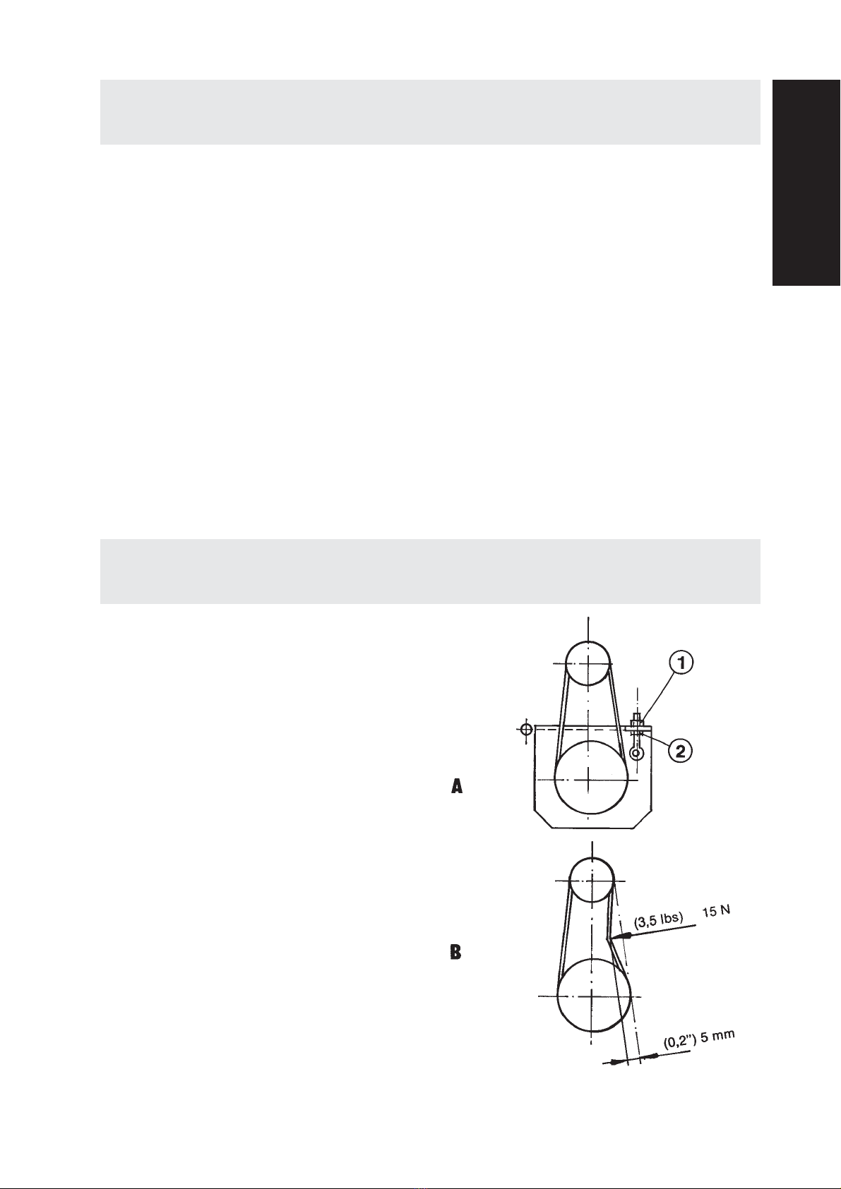
Provkörning __________________ 9
Underhåll __________________9-10
Tillbehör ____________________ 11
Garanti _____________________ 11
Felsökning __________________ 12
Reservdelar________________44-46
Vakuumventil ________________ 56
Tillverkarens deklaration _______ 57
Dustcontrol Worldwide ________ 58
Contents
Safety Considerations _________ 13
Dimensions and Arrangements__ 13
Technical Data _______________ 14
System Description ___________ 15
Installation ________________15-16
Test Running_________________ 17
Service _____________________ 18
Accessories __________________ 19
Warranty ____________________ 19
Trouble Shooting _____________ 20
Spare Parts ________________53-55
Vacuum relief valve ___________ 56
Manufacturer’s declaration _____ 57
Dustcontrol Worldwide ________ 58
Inhaltsverzeichnis
Sicherheitsvorschriften ________ 21
Maße und Aufstellung _________ 21
Technische Daten _____________ 22
Funktionsbeschreibung ________ 23
Installation ________________23-24
Probelauf ___________________ 25
Wartung __________________25-26
Zubehör ____________________ 27
Garantie ____________________ 27
Fehlersuche _________________ 28
Ersatzteile _________________53-55
Vakuumventil ________________ 56
Erklärung des herstellers _______ 57
Dustcontrol Worldwide ________ 58
SVENSKAENGLISHDEUTSCH
Inhoud
Veiligheidsvoorschriften _______ 29
Afmetingen__________________ 29
Technische gegevens__________ 30
Systeem beschrijving __________ 31
Installatie _________________31-32
Testen ______________________ 33
Service ___________________33-34
Accessoires __________________ 35
Garantie ____________________ 35
Probleemoplossingen _________ 36
Onderdelen________________53-55
Onderdrukklep _______________ 56
Manufacturer’s declaration _____ 57
Dustcontrol Wereldwijd ________ 58
NEDERLANDS
Sommaire
Conditions de sécurité _________ 37
Dimensions et Arrangements ___ 37
Données techniques __________ 38
Description du système ________ 39
Installation ________________39-40
Test de fonctionnements _______ 41
Service ___________________41-42
Accessoires __________________ 43
Garantie ____________________ 43
Dépannage__________________ 44
Pieces detachees ___________53-55
Soupape de Régulation ________ 56
Déclaration du Fabricant _______ 57
Dustcontrol Worldwide ________ 58
FRANCAIS

TPR 50, 30 kW - 4 Part No 9050
Sikkerhedsregler______________ 45
Tekniske data ________________ 46
Funktionsbeskrivelse __________ 47
Dimensioner og opstilling ______ 47
Installation ________________48-49
Afprøvning __________________ 49
Vedligeholdelse ____________50-51
Tilbehør_____________________ 51
Garanti _____________________ 51
Fejlnding___________________ 52
Reservedele _______________53-55
Vakuumventil ________________ 56
EU-konformitetserklæring ______ 57
Dustcontrol Worldwide ________ 58
DANSK
Indholdsfortegnelse

TPR 50, 30 kW - 5 Part No 9050
Säkerhetsföreskrifter
Läs hela detta instruktionshäfte innan maskinen
startas.
Utrustningen får monteras och skötas endast av behö-
riga personer som tagit del av denna skrift. Dustcontrol
ansvarar ej för skador på utrustningen som uppkommit
pga felaktig installation eller felaktigt handhavande av
utrustningen.
Varning! Vid användandet av elektriska maskiner ska
nedanstående grundläggande säkerhetsföreskrifter
följas för att minska risken för brand, elstöt eller
personskada.
1. Arbetsmiljön
Håll utrymmet vid centralenheten rent. Lagra el-
ler hantera inte lättantändliga vätskor eller gaser
i närheten.
2. Överbelastning
Vid larmindikation - återstarta inte maskinen för-
rän felet är konstaterat och åtgärdat. Använd ma-
skinen för avsett ändamål och följ föreskrifterna
för det material som sugs.
3. Kroppsskador
Varning för starkt undertryck
Starta aldrig pumpen utan att kanalerna är an-
slutna och justera aldrig vakuumventilen under
drift. Låt aldrig sugpunkten komma i kontakt med
någon kroppsdel. Prova aldrig undertrycket med
handflatan eller andra kroppsdelar. Det starka
undertrycket kan skada hudens blodkärl.
Varning för het utblåsluft.
Tänk på att utblåsningsluften kan vara 150 oC
varm.
4. Elektricitet
En separat, låsbar arbetsbrytare måste installeras
och vara lätt åtkomlig från den plats där pumpen
står. Försök aldrig att på egen hand ändra elek-
triska kopplingar. Ett fel kan medföra livsfara.
Den elektriska installationen får endast utföras av
behörig elektriker. Se också punkt 7 - Varning.
5. Viktig åtgärd
Bryt och lås arbetsbrytaren före demontering av
skyddsplåtar och kanaler.
6. Kontroll av skador
Kontrollera regelbundet att maskinen inte har ska-
dor eller förslitningar. Uppstår skador ska dessa
åtgärdas av en auktoriserad serviceverkstad som
är godkänd av Dustcontrol eller av Dustcontrol
själva.
7. Varning
Använd endast tillbehör och utbytesdelar som
nns i Dustcontrols katalog.
OBS! Vid användandet av felaktiga delar eller
piratdelar (framförallt lter och plastsäckar) kan
maskinen läcka hälsofarligt damm med person-
skador som följd.
Mått och uppställning
TPR 35, TPR 40, TPR 43, TPR 47, TPR 50
SVENSKA

TPR 50, 30 kW - 6 Part No 9050
Tekniska data
TRYCKALSTRING OCH EFFEKTFÖRBRUKNING
kPa Pu
60
50
40
30
20
10
0
10
20
30
kW P
200 400 600 800 1000 1200 1400 1600
7
6
4
8
1
7
5
3
2
1
6
8
425
3
Q
m3/h
1. TPR 35 11 kW
2. TPR 40 15 kW
3. TPR 43 18,5 kW
4. TSR 43 18,5 kW
5. TPR 47 22 kW
6. TSR 47 22 kW
7. TPR 50 30 kW
8. TSR 50 30 kW
Benämning TPR 35 TPR 40 TPR 43 TSR 43 TPR 47 TSR 47 TPR 50 TSR 50
Standardmotor kW 11 15 18,5 18,5 22 22 30 30
Varvtal rpm 3500 4000 4300 4300 4700 4700 5000 5000
Vikt kg 400 400 430 430 450 450 530 530
Max dP kPa 22 26 28 46 29 50 30 54
Nominellt tryck kPa 20 22 22 35 23 37 25 40
Max Q m3/h 1000 1200 1400 650 1500 700 1600 800
Ljudnivå
kåpa 1m dB(A) 66 66 66 66 66 66 66 66
Inlopp/Utlopp Ømm 160/160 160/160 160/160 108/108 160/160 108/108 160/160 108/108
MÄRKEFFEKT
Hz TPR 35 TPR 40 TPR 43 TSR 43 TPR 47 TSR 47 TPR 50 TSR 50
11 kW 15 kW 18.5 kW 18.5 kW 22 kW 22 kW 30 kW 30 kW
220-240/
380-420 50 - 106802 107202 107252 107702 107752 109202 109252
380-420/
660 50 106600 106800 107200 107250 107700 107750 109200 109250
500 50 - 106801 107201 107251 107701 107751 109201 109251
575 60 - 106806 107206 107256 107706 107756 109206 109256
220/440 60 - 106804 107204 107254 107704 107754 109204 109254
V
Art. nr.
Kapacitetskurvorna är mätta som den faktiskt tillgängliga kapaci-
teten i ett sugsystem. Det innebär att utloppsförluster från ett
normalt utlopp (ljuddämpare och backventil/böj) har subtraherats
från pumpens/fläktens tryckalstring. Med diffusor på utlopp kan
högre undertryck erhållas. Angivna luftflöden gäller luft av normalt
tryck (101,3 kPa) och normal temperatur (20oC).
Vakuumalstrarna kan användas även för blås och ger då ett högre
tryck än vid sug.

TPR 50, 30 kW - 7 Part No 9050
Funktionsbeskrivning
Sidokanalstyp
DustcontrolTPR är turbopumpar av sidokanalstyp
med två turbinhjul. Mellan inlopp och utlopp löper
skovlar genom en passage med mycket små spel.
Det är därför viktigt att det inte kommer in några
partiklar i pumpen - haveririsk! Turbopumpen
komprimerar luft och det är därför helt naturligt
att den blir het under drift.
Kylluft
Dustcontrols TPR turbopumpar är remdrivna i två
parallellkopplade steg. Kylluft släpps in genom
en vakuumventil vars trycknivå kan justeras.
Anläggningens trycknivå kan då hållas konstant
även om luftödet ändras.
Luft hämtas från pumpens botten. Luftens pas-
sage får inte hindras. Skyddsgaller mot löv, pap-
per etc levereras med som standard.
Backventil
TPR har backventil på inloppet för att förhindra
baksug.
Remdrift
Pumpen är remdriven. Utväxling och motor-stor-
lek bestämmer pumpens kapacitet.
Om man behöver ändra kapaciteten är det möjligt
att byta motor, remskivor och kilremmar. Om
detta blir aktuellt - kontakta Dustcontrol för mer
information. Se adresser och telefonnummer
längst bak i denna instruktion.
Termoprotektor
Turbopumpen är utrustad med en termo pro- tek-
tor. Om friliggande lagret blir varmare än 120 OC
löser termoprotektorn ut.Termopro-tektorn måste
vara kopplad till elskåpet.
Installation
A. Tillåtna belastningar vid montage.
B. Lyft ej från denna sida.
SVENSKA

TPR 50, 30 kW - 8 Part No 9050
Installation
C. Pumpen ska monteras på betongfundament. Den är även förberedd för
montering ovanpå en annan pump.
1. Skruva fast pumpen i betongplattan.
2. Ta loss skyddsplåtarna och skruva vid behov
fast skyddsgallren. Se gur A.
3. Anslut inlopp och utlopp. Starta aldrig pumpen
utan att kanalerna är anslutna.
4. Inloppet ska alltid vara anslutet till en stoftav-
skiljare med filter - se figur B. Inga partiklar
får komma in i pumpen.
5. Utloppet kan utrustas med ljuddämpare. Ut-
loppsljudet sänks då från ca 75 dB(A) till ca
62-64 dB(A). Se Tillbehör på sidan 10.
6. Om utloppet riktas uppåt ska det avslutas med
en böj så att inte regnvatten kommer in i utlop-
pet, se gur C. Tänk på att blåsluften kan vara
100-150 OC varm.
7. Den elektriska installationen ska göras av be-
hörig elektriker. En separat, låsbar arbetsbry-
tare ska monteras i närheten av pumpen.
8. Pumpens termoprotektor måste kopplas in
för att garantin ska gälla.
9. Styrskåpet ska utrustas med termiskt mo-
torskydd som ställs och testas av elektriker.
Kontrollera att pumpen har rätt rotationsrikt-
ning.

TPR 50, 30 kW - 9 Part No 9050
Provkörning
1. Se till att arbetsbrytaren är frånslagen och
låst. Kontrollera remspänningen (se figur B
på nästa sida). Låt remskivorna rotera och
lyssna så att inga skrapande ljud hörs. Kon-
trollera att inlopp och utlopp är ordentligt
anslutna samt att vakuumventilen sitter på
plats.
2. Montera skyddsplåtarna. Kontrollera så att
det är möjligt att starta pumpen utan att någon
som benner sig i närheten kan skadas och
att alla uttag i systemet är stängda.
3. Anslut en manometer till sugsidan så nära
pumpen som möjligt. Manometern ska vara
kalibrerad till minst -50 kPa.
4. Slå till arbetsbrytaren. Starta pumpen och
lyssna. En hög ton från turbinhjulen hörs.
När pumpen hämtar luft från vakuumventilen
hörs även ett svagt väsande.
5. Mät trycket på sugsidan. Jämför med
det tryck som anläggningen är dimen-
sionerad för. Trycket kan justeras genom att
vakuumventilens inställning ändras, se sidan
9 - Ändring av vakuumventilens under-
tryck.
6. Kontrollera sugsystemets funktion.
7. Öppna det antal uttag som systemet är dimen-
sionerat för och kontrollera att vakuumventi-
len nu är helt stängd.
8. Det är helt normalt att pumpens utlopp blir
mycket varmt efter någon timmes körning.
Underhåll
Pumpen ska ses över minst två gånger per år och
smörjas enligt smörjintervallerna, se sid 9.
1. Starta pumpen och lyssna efter missljud. När
alla uttag är stängda ska det höras ett svagt
väsande från vakuumventilen.
2. Stäng av pumpen och lås arbetsbrytaren.
3. Ta bort skyddsplåtarna.
4. Dra runt remskivorna och lyssna efter miss-
ljud.
5. Kontrollera slitaget på remmarna och byt vid
behov. Antingen byter man alla remmar eller
ingen. Se gur A.
Byte av remmar
- Lyft motorn med mutter (1) och lossa rem-
marna.
- Byt remmar.
- Spänn remmarna med mutter (2). Justera
spänningen. Se gur B.
SVENSKA

TPR 50, 30 kW - 10 Part No 9050
Underhåll
Δ p TPR 50
22 kPa 1500 h
25 kPa 1500 h
28 kPa 1000 h
30 kPa 750 h
40 kPa -
6. Kontrollera att remskivorna inte är skeva och
att axlarna är parallella. Remskivorna ska
ligga i linje med varandra. Pumpens vinkel kan
justeras med skruv (3), gur C.
7. Turbopumpens lager ska smörjas med
Dustcontrol lagerfett för turbopumpar, art
nr 9928.
Smörjning
- Pressa in fett i främre lagrets smörjnippel (4).
Se gur C.
- Lossa bakre lagrets kylfläns (5). Kontrollera
fettets kondition och fyll på nytt fett till 2/3 av
lockets volym.
- Kontrollera O-ringen (Art nr 4789) och sätt
tillbaka kylänsen.
Smörjintervall
8. Demontera, rengör och smörj vakuumven-
tilen. Se gur D nedan. Kontrollera gummi-
packningen, g E. Om den är sprucken eller
har hårdnat bör den bytas (art nr 4710).
Kontrollera stötdämparens (figur F) funk-
tion.
Ändring av vakuumventilens undertryck
Vakuumventilen är inställd på ett nominellt un-
dertryck (18 kPa). Om detta behöver ändras gör
du så här:
- Anslut en manometer till sugsidan och mät
vid full strypning.
- Stäng av strömmen och demontera vakuum-
ventilen.
D1.
4.
2.
3.
E- Ta loss dämparlocket (1) och mät avstånd
A.
- Justera genom att lossa kontramuttern (3).
Vrid därefter fjädertallriken (4). E n hop -
tryckning av ädern (2) med 1,5 mm ger ca
1 kPa större undertryck.
- Montera vakuumventilen och kontrollera
undertrycket.
9. Se över anslutningar och kablar så att de
är intakta.
10. Sätt tillbaka skyddsplåtarna, slå på strömmen
och provkör pumpen.
F

TPR 50, 30 kW - 11 Part No 9050
Tillbehör
Garantitiden är ett år vid enskiftsarbete eller
motsvarande tid vid flerskift. Garantin avser
fabrikationsfel och gäller under förutsättning att
maskinen används på normalt sätt och får det un-
derhåll som krävs. Dustcontrol tar inte ansvar för
maskiner utustade med annat än originaldelar.
Termoprotektorn måste vara inkopplad.
Garanti
A
Ljuddämpare
Art nr Ansl Dimensioner
3182 ø160 L=1200, ø355
3183 ø160 L=600, ø355
3184 ø160 L=600, ø260
Art nr A
- 75 dB(A)
3184 64 dB(A)
3182 62 dB(A)
Reparationer ska utföras av Dustcontrol eller av
personal som godkänts av Dustcontrol. I annat
fall förverkas garantin.
SVENSKA

TPR 50, 30 kW - 12 Part No 9050
Felsökning
Orsak
Elen avstängd.
Termoprotektorn utlöst.
Motorskyddet i elskåpet
utlöst - motorn
överbelastad.
Elen når inte fram.
Arbetsbrytaren
avslagen.
Felaktig säkring.
Termisk säkring för lågt
ställd.
Rör och slangar ej anslut-
na eller stopp i dessa.
Det ns ingen uppsam-
lings-anordning ansluten
till stoft-
avskiljaren.
Pumpen roterar åt fel håll.
Kilremmarna har gått av.
Hål på slangar eller otätt
rörsystem.
Igensatt lter i stoft-avskil-
jaren.
Partiklar kan ha kommit in i
pumpen.
Problem
Motorn går inte.
Motorn stannar direkt efter
start.
Motorn går men anläggningen
suger inte.
Motorn går men anläggningen
suger dåligt.
Onormalt ljud från pumpen.
Åtgärd
Slå på elen.
Om termoprotektor på pump
brutit ska felet undersökas och
åtgärdas på pumpen. Därefter
kan larmet återställas med
RESET.
Om motorskydd löst ut ska
felet undersökas och åtgärdas.
Därefter kan motorskyddet
återställas.
Låt en elektriker se över
kopplingar och ledningar.
Undersök varför den stängts
av och om pumpen är redo att
startas. Slå sedan på arbets-
brytaren.
Byt till rätt säkring.
Låt elektriker justera.
Anslut eller rensa.
Anslut en uppsamlings-
anordning (säck eller annan
behållare).
Låt en elektriker åtgärda.
Byt kilremmarna.
Kontrollera.
Rensa eller byt.
Stäng av och beställ
service.

TPR 50, 30 kW - 13 Part No 9050
Safety Considerations
Read all instructions before attemting to operate this
machine.
The equipment must be installed and maintained pro-
perly by qualied personnel who have study this user
instruction. Dustcontrol does not take responsibility
for defective installation or maintenance.
Warning! When using electric machines, basic safety
precautions should always be followed to reduce the
risk of re, electric shock and personal injury, inclu-
ding the following:
1. Work area environment
Keep the area around the central unit clean. Do
not store or work with ammable liquids or gases
near the machine.
2. Overload
If there is an alarm signal it should be carefully
checked out to see that the machine is undamaged.
If there are any damaged parts these should be
repaired by a Dustcontrol authorized service
centre. Always follow the regulations pertinent to
the material you are working with. Do not use the
machine for purposes that it is not intended for.
3. Bodily injuries Warning - High negative pres-
sure
Do not start the pump without having it connec-
ted to the duct work. Do not adjust the vacuum
relief valve while the pump is operating. Never
let the suction come in contact with parts of the
body, for example a hand. The pump generates a
high negative pressure, severe injury may result.
Warning - Very hot exhaust air
Exhaust air can be very hot, up to 150OC.
4. Electricity
A separate lockable disconnect must be installed
where it is readily accessible to the pump. Do
not repair the electric components yourself, get
somebody qualied. Faults may cause injury. The
electrical connections may only be performed by
a certied electrician. See also under section 7,
’Warning’.
5. Important measure
The electrical disconnect should be locked in the
”o ”position before demounting the safety panels
or ducting.
6. Checking for damage
Check the machine regularly for damage. If there
are any damaged parts these should be repaired
by a Dustcontrol authorized service centre.
7. Warning
Use only accessories and replaceable parts which
are available in Dustcontrol catalogue. When
using non-genuine parts, especially filters and
plastic sacks, dust leaks could occur which may
be hazardous to health.
Dimensions and Arrangements
TPR 35, TPR 40, TPR 43, TPR 47, TPR 50
ENGLISH

TPR 50, 30 kW - 14 Part No 9050
Technical Data
CAPACITY AND POWER CONSUMPTION
kPa Pu
60
50
40
30
20
10
0
10
20
30
kW P
200 400 600 800 1000 1200 1400 1600
7
6
4
8
1
7
5
3
2
1
6
8
425
3
Q
m3/h
1. TPR 35 11 kW
2. TPR 40 15 kW
3. TPR 43 18,5 kW
4. TSR 43 18,5 kW
5. TPR 47 22 kW
6. TSR 47 22 kW
7. TPR 50 30 kW
8. TSR 50 30 kW
POWER RATING
Hz TPR 35 TPR 40 TPR 43 TSR 43 TPR 47 TSR 47 TPR 50 TSR 50
11 kW 15 kW 18.5 kW 18.5 kW 22 kW 22 kW 30 kW 30 kW
220-240/
380-420 50 - 106802 107202 107252 107702 107752 109202 109252
380-420/
660 50 106600 106800 107200 107250 107700 107750 109200 109250
500 50 - 106801 107201 107251 107701 107751 109201 109251
575 60 - 106806 107206 107256 107706 107756 109206 109256
220/440 60 - 106804 107204 107254 107704 107754 109204 109254
V
Part No.
The capacity curves for Dustcontrol vacuum producers have been
measured and are stated empirically. Outlet pressure losses from a
normal outlet (silencer, back-flow valve/bend) have been accounted
for in the curve. Additional equipment such as a diffuser can result in
increased pressure loss and must be taken into consideration.
Stated air-flows are for standard air (101.3 kPa@ 20oC).
The stated curves are for negative application, all pressures
stated are assumed to be below relative atmospheric pressure at
sea level. These devices can also be used for positive pressure
application and will generate a greater pressure differential.
Description TPR 35 TPR 40 TPR 43 TSR 43 TPR 47 TSR 47 TPR 50 TSR 50
Motor kW 11 15 18,5 18,5 22 22 30 30
Pump RPM rpm 3500 4000 4300 4300 4700 4700 5000 5000
Weight kg 400 400 430 430 450 450 530 530
Max dP kPa 22 26 28 46 29 50 30 54
Nom. Pressure
kPa 20 22 22 35 23 37 25 40
Max Q m3/h 1000 1200 1400 650 1500 700 1600 800
Sound Level of
Unit 1m dB(A) 66 66 66 66 66 66 66 66
Inlet/Outlet Ømm 160/160 160/160 160/160 108/108 160/160 108/108 160/160 108/108

TPR 50, 30 kW - 15 Part No 9050
System Description
Regenerative blowers
Dustcontrol’s turbopumps are regenerative blo-
wers. TPR has two impellers that are connected
for parallel ow. The impellers rotate in the blower
housing through extremely low tolerances. The
pump cannot tolerate contaminated airow. TPR
compresses air and it is therefore natural that it
becomes hot while running.
Cooling air
Turbopumps with TPR designation are parallel
connected two stage belt driven units. Cooling
air is bled into the pump through a vacuum relief
valve which is adjustable. The vacuum pressure
in the system is thereby maintained at a constant
level even if the airow changes.
The motor and vacuum relief valve receive cooling
air from the bottom of the unit housing. The free
passage of cooling air must be ensured. As stan-
dard screen skirts are delivered with the pump
as an protecting against leaves, papers etc.
Back ow valve
The pump is delivered standard with a back ow
relief valve. In multiple pump installations air will
not ow back through a non-operating pump.
Belt drive
The pump is belt driven. Drive ratio and motor
size determine the capacity of the pump.
If changes are to be made to performance charac-
teristic of the pump, this can be done by changing
the motor and drive ratio. Contact Dustcontrol
and you will recieve more information. Please see
addresses and phone numbers on the last page
of this document.
Thermal overload protection
For protection on the pump bearings the pump
has thermal protection which will shut down the
pump at 120OC. The thermal protection has to be
connected to the control panel.
Installation
A. Allowed pressures during installation.
B. Do not lift from this side.
ENGLISH

TPR 50, 30 kW - 16 Part No 9050
Installation
C. The pump should be installed on a concrete pad. A second pump may be
mounted on the top of the rst pump.
1. Ancor the pump to the concrete pad.
2. Remove the pump covers and assemble the
protection screen skirt if this is required (A).
3. Connect the ducting to both the inlet and the
outlet. Do not start the pump without having
it connected to the ductwork.
4. The pump inlet should always be connected
to a separator with a lter unit (B). The pump
cannot tolerate contaminated airow .
5. Extra silencing can be installed if the outlet
sound level is to be lowered from appro-xima-
tely 75 dB(A) to approximately 62-64 dB(A).
See Accessories on page 18.
6. If the outlet is vertical, and exposed to the
elements, rain protection should be installed
(C)Exhaust air can be very hot, up to 150 OC.
7. Electrical connections may only be performed
by a certied electrician. A separate lockable
disconnect should be installed where it is rea-
dily accessible and within view of the pump.
8. Thermal overload protection must be installed
to validate the warranty.
9. The control panel must be equipped with an
overload protection that should be adjusted
and tested by a certified electrician. Check
for correct motor rotation.

TPR 50, 30 kW - 17 Part No 9050
Test Running
1. Verify that the power is locked out. Inspect
the belt tension (Figure B next page), rotate
the pump and listen for any sound indicating
worn bearings or misaligned impellers.
Check that the inlet and outlet are properly
connected. Also check that the vacuum relief
valve is connected.
2. Mount the covering panels. Check that no
persons can be hurt if the pump starts and
that all outlets are closed.
3. Connect a manometer for negative pressure
calibrated to min. -50 kPa to the suction side
as close to the pump as possible.
4. Power up the pump and listen carefully for
the following sounds; A high pitch whine is
normal sound from the impeller blades. As
pump draws cooling air from the vacuum
relief valve a weak hissing should be heard.
5. Measure the pressure. Compare with the di-
mension point. The pressure can be adjusted
by adjustment of the vacuum relief valve.
See page 17 - Adjusting the vacuum relief
valve.
6. Check the function and tightness of the con-
nected exhaust system.
7. Open the number of outlets the system is
dimensioned for. The vacuum relief valve
should now be totally closed.
8. It is normal that the pump becomes hot during
operation.
The pump should be inspected at least twice a year
and lubricated according to the lubrication intervals.
See page 17.
1. Start the pump and listen for abnormal sounds.
When all outlets are closed a weak hissing
sound should be heard from the vacuum relief
valve.
2. Shut o the pump and lock out the electrical
service.
3. Remove the protective panels from the pump.
4. Rotate the pump manually and listen for any
sounds indicating a worn bearing or misligned
impellers.
5. Check the condition and tension of the drive
belts. The drive belts are matched, therefore
new and old belts should never be used to-
gether. Always change the whole set. (A).
Changing the belts
- Lift the motor mounting plate with nut (1).
- Change belts.
- Tighten the belts with nut (2) and adjust to the
tension illustrated (B).
Service
ENGLISH

TPR 50, 30 kW - 18 Part No 9050
Service
6. Check that the axles, pump and motor are paral-
lel and the pulleys are true. The belts should not
run on an angle into the pulleys.The inclination
of the pump can be changed with screw (3), g
C.
7. The bearings of the turbopump should be
lubricated with Dustcontrol bearing grease for
turbopumps, Part No. 9928.
Lubrication
- The front bearing should be lubricated using
the grease nipple (4), fig (C). Press grease in
until it comes out along the axle.
- The back bearing should be lubricated by re-
moving the nned bearing cover plate (5) and
checking the condition of the grease. Fill the
cavity 2/3 full with new grease.
- Exchange the O-ring, Part No. 4789 and replace
the bearing cover plate.
Δ p TPR 50
22 kPa 1500 h
25 kPa 1500 h
28 kPa 1000 h
30 kPa 750 h
40 kPa -
8. Disassemble the vacuum relief valve (D).
Clean and lubricate shaft and bearings.
Check the rubber gasket (E). Change
if cracked or harden (Part No. 4710).
Check the function of the hydraulic
damper (F).
Adjusting the vacuum relief valve
The valve is pre-adjusted with a negative pressure
(18 kPa). If this is to be adjusted the following
procedure is used:
- Connect a manometer to the suction side and
measure with fully closed inlet.
D1.
4.
2.
3.
E
- Shut down the pump and demount the vacuum
relief valve.
- Remove the damper cover (1) and measure
distance A.
- Loosen the locking nut (3) and adjust the
spring tension by turning the spring plate (4).
The compression of the spring (2) determines
the opening pressure. Changing the distance
A by 1.5 mm will give a corresponding change
in pressure of 1 kPa.
- Remount the valve after adjustment and test
the pressure.
9. Inspect all cables and connections, repair
if neccessary.
10. Remount the protective panels, power up
the pump and give it a test run.
F
Lubrication Interval

TPR 50, 30 kW - 19 Part No 9050
Accessories
The warranty period is for one full year of single
shift operation or equivalent in multishift opera-
tion. The warranty covers manufacturing defects
and is valid under the condition that the machine
is used under normal conditions on the task for
which it was designed and is maintained properly.
This warranty is null and void for machines equip-
ped with other than original spare parts.
Thermal overload protection must be installed.
Warranty
A
Silencer
Part No Conn. Dimensions
3182 ø160 L=1200, ø355
3183 ø160 L=600, ø355
3184 ø160 L=600, ø260
Art nr A
- 75 dB(A)
3184 64 dB(A)
3182 62 dB(A)
Warranty repairs must be performed by Dustcon-
trol or their authorized representatives. Unautho-
rized repairs render this warranty null and void.
ENGLISH

TPR 50, 30 kW - 20 Part No 9050
Trouble Shooting
Fault
Electrical supply is not
connected.
Thermal overload tripped.
The motor protection trip-
ped.
Electrical power does not
reach the machine.
Electrical disconnect
locked out.
Incorrect fuse.
The thermal overload
incorrectly set.
Suction tubing not con-
nected.
Plugged tubing or hoses.
There is no plastic sack or
container attached to the
ler unit.
Pump rotation backwards.
Drive belt broken.
Leakage in the ductwork.
Plugged lters.
Foreign matter in the
pump.
Problem
Motor will not run.
The motor stops directly after
starting.
Motor runs but no suction.
Pump runs but poor suction.
Abnormal sound from the
pump.
Solution
Connect.
If the thermal overload protection
of the turbo pump is tripped,
the fault must be located and
corrected before operating the
system. Thereafter, the indicator
can be reset.
If the motor overload protection
trips, the fault must be located
and corrected. Thereafter the
motor overload protection can
be reset.
A qualied electrician should
check supply.
Find the person responsible for
the lock out and check to see
if system is clear for operation.
Reverse the lock out.
Change to correct fuse rating
and type.
Electrician should be called for
investigate.
Connect the tubing.
Clean.
Connect a plastic sack or a
container.
Electrician should take care of.
Change.
Locate and repair.
Check the lters and clean or
change if necessary.
Turn o the pump and order
service.
Other manuals for TPR 50
1
Table of contents
Languages:
Other Dustcontrol Ventilation Hood manuals
Popular Ventilation Hood manuals by other brands

Electrolux
Electrolux PLHV36W6CC owner's guide

Frigidaire
Frigidaire FRIGIDAIRE installation instructions

Franke
Franke FKU 908-H I TC Instructions for use and installation

Beko
Beko BHCI98841BBHSI installation instructions

FALMEC
FALMEC FDMOV30W5SB Instruction booklet

Rinnai
Rinnai RH-C107-GC installation manual

Infiniton
Infiniton CMPTRAL-NG61 instruction manual

AEG
AEG DK 9160 D Operating and installation instructions

Classique
Classique CLH60SLMSS user manual

Gaggenau
Gaggenau AI 442 720 use and care manual

Futuro Futuro
Futuro Futuro Classic Range hood Instruction booklet

JSI
JSI 4180-40-IX Installation Instructions, User Guide, Warranty Information