Cod. 710.0134.20.00 Rev06B –04.2016 1
- GB -
CONTENTS
1. GENERAL INFORMATION
1.1 Functional Description 3
1.2 Safe Use of the Dryer 3
2. INSTALLATION
2.1 Acceptance and Transportation 3
2.1 Storage and installation location 3
2.1 Unpacking 4
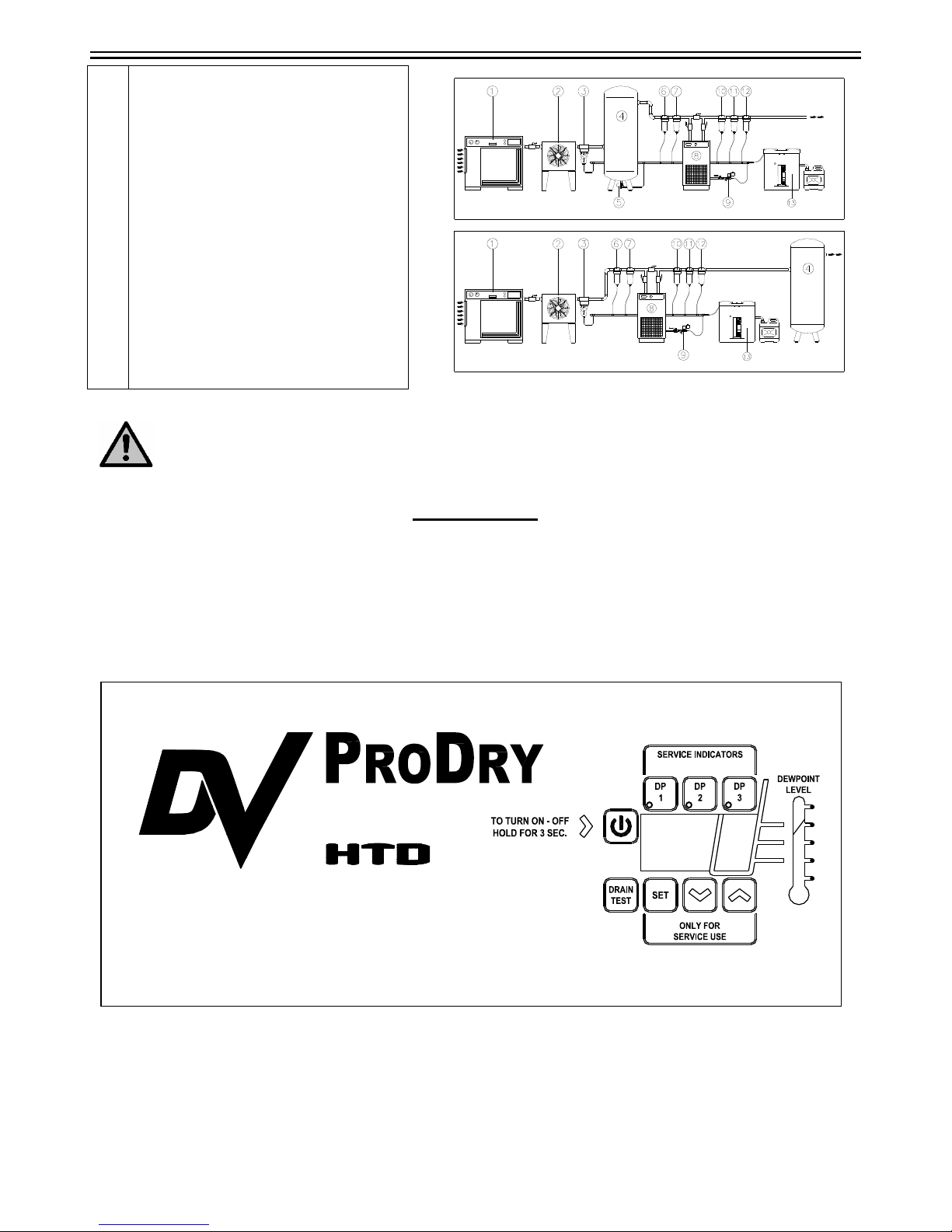
2.3 Installation 4
3. START UP
3.1 Control Panel 5
3.1.1 Keys function 6
3.1.2 Parameters Programming 7
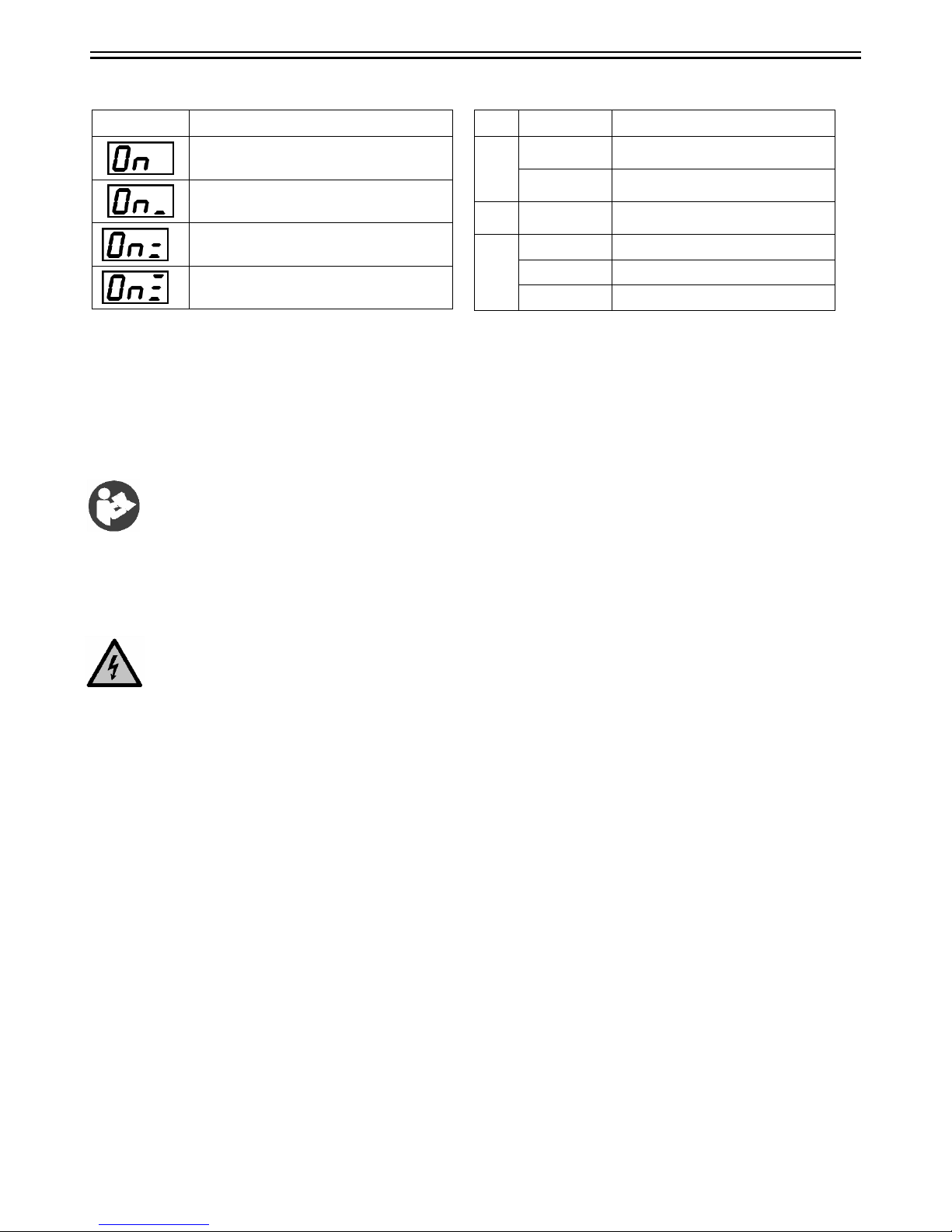
3.1.3 Anomaly Warning 7
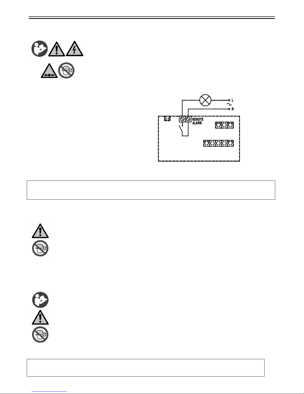
3.1.4 Remote signalling Alarm 8
3.2 Before Start Up 8
3.3 Start Up 8
4. MAINTENANCE,
TROUBLESHOOTING AND
DISMANTLING
4.1 Maintenance 9
4.2 Troubleshooting 9
4.3 Dismantling 11
ATTACHMENTS TO THIS
MANUAL
A) Air and Refrigeration Circuit 32-33
B) Electric Circuit Diagram 34-35
C) Technical Data Sheet 36-39
D) Spare part list 40-41
- F -
TABLE DES MATIERES
1. INFORMATIONS GENERALES
1.1 Description fonctionnelle 13
1.2 Utilisation du séchoir en toute sécurité 13
2. INSTALLATION
2.1 Réception et transport 13
2.2 Stockage et lieu d'installation 13
2.2 Déballage 14
2.3 Installation 14
3. MISE EN SERVICE
3.1 Pupitre de commande 15
3.1.1 Fonction des touches 16
3.1.2 Programmation des paramètres 17
3.1.3 Signalisation des anomalies 17
3.1.4 Signalisation d’alarme a distance 18
3.2 Opérations préliminaires
à la mise en marche 18
3.3 Mise en marche 18
4. ENTRETIEN, RECHERCHE
DES PANNES ET
DEMANTELEMENT
4.1 Entretien 19
4.2 Recherche des pannes 19
4.3 Démantèlement 21
ANNEXES AU MANUEL
A) Circuit air et frigo 32-33
B) Schéma électrique 34-35
C) Fiches techniques 36-39
D) Liste des pièces détachées 40-41
- E -
ÍNDICE
1. INFORMACIONES GENERALES
1.1 Descripción funcional 21
1.2 Uso seguro del secador 21
2. INSTALACIÓN
2.1 Aceptación y transporte 21
2.2 Almacenamiento y ubicación de la
instalación 22
2.3 Desembalaje 22
2.4Instalación 22
3. PUESTA EN MARCHA
3.1 Panel de control 23
3.1.1 Funcionamiento de las teclas 23
3.1.2 Programación de parámetros 24
3.1.3 Señalización de anomalías 24
3.1.4 Indicación de alarmas remotas 25
3.2 Preliminares de arranque 25
3.3 Arranque 25
4. MANTENIMIENTO, DETECCIÓN
DE AVERÍAS Y
DESMANTELAMIENTO
4.1 Mantenimiento 26
4.2 Detección de averías 26
4.3 Desmantelamiento 28
ADJUNTOS A ESTE MANUAL
A) Circuitos de aire y refrigerante 32-33
B) Esquema eléctrico 34-35
C) Fichas técnicas 36-39
D) Lista de piezas de repuesto 40-41