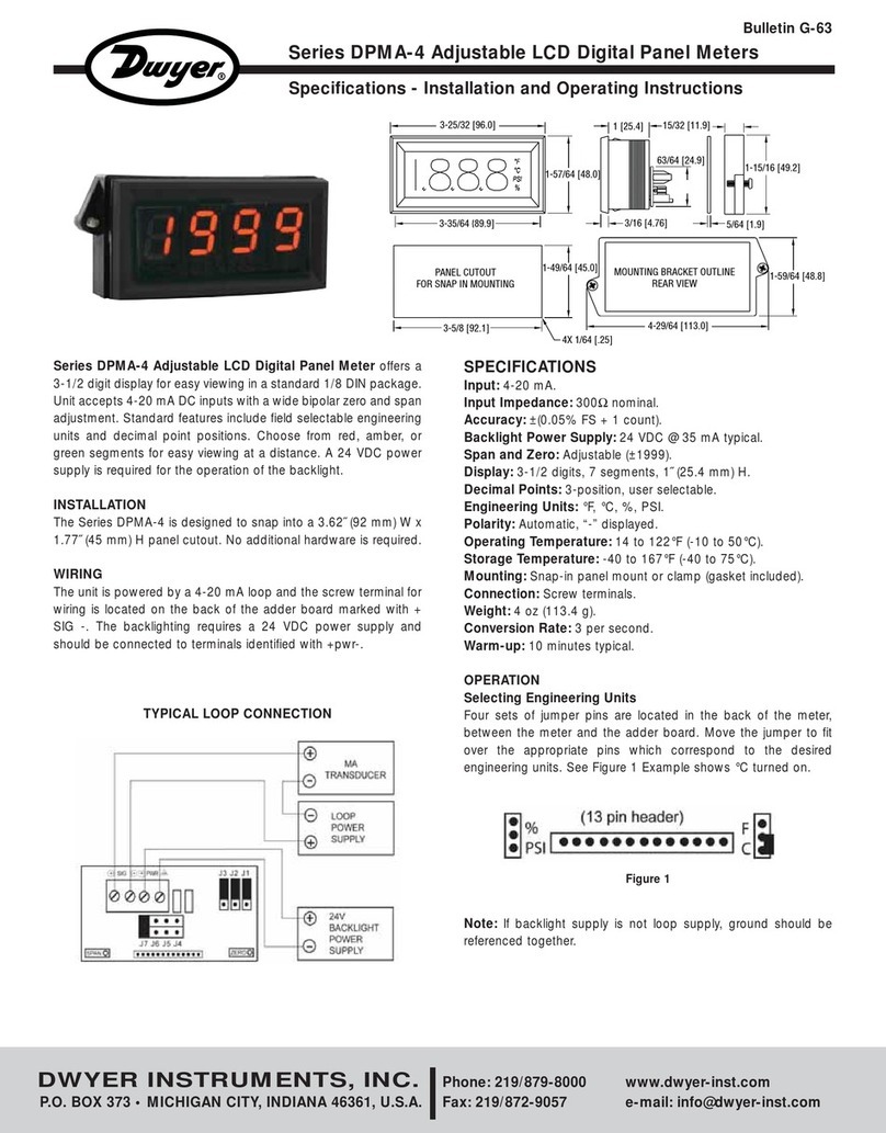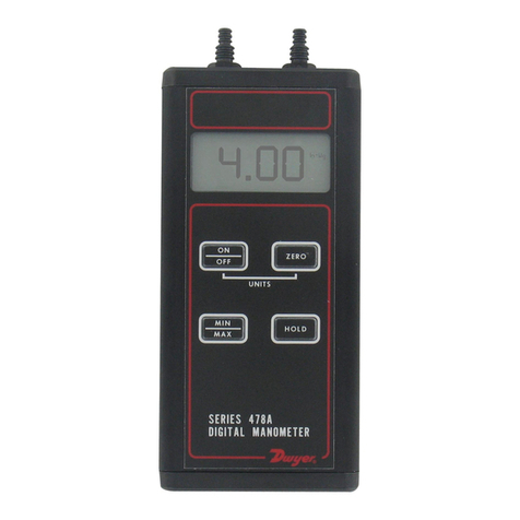
Fig. 3 Fig. 4
Fig. 5 Fig. 6
Fig. 7
Fig. 5B Fig. 6B
Surface Mounting: Drill appropriate holes in panel, using the dimensions
shown in Fig. 2. Hold the flowmeter in position in front of the panel and
install the clamp bolts from the rear. (The mounting clamps may be used
as washers, if desired, by installing them backwards or straightening them
out.) Pipe up inlet and discharge following the directions in the previous
sections.
Surface Mounting on Piping Only: An alternate method of surface
mounting, omitting the clamp bolts and supporting the flowmeter solely on
the connecting piping, is possible. For this method, extra-long or straight
pipe threads should be used so that nuts may be run onto the pipe and
later tightened against the back of the panel to retain the unit in proper
position. Use appropriate hole layout in formation from Fig. 2, but omit the
small holes.
Surface Mounting on Piping Only Without Panel: For a temporary or
laboratory type installation, the panel may be omitted altogether and the
flowmeter installed directly in rigid piping. Its light weight permits this with-
out difficulty.
OPERATION
To start system, open valve slowly to avoid possible damage. Control
valves on BV and SSV models are turned clockwise to reduce flow,
counter-clockwise to increase flow. A nylon insert is provided in the thread-
ed section of the valve stem to give a firm touch to valve and to prevent
change of setting due to vibration.
The performance of low range units used in air or gas applications may be
affected by static electricity. Excessive static charge may cause the ball
float to behave erratically or provide a false reading. To ensure the proper
function of the unit, the application should be designed to minimize or dis-
pel static electricity.
The standard technique for reading a Variable Area Flowmeter is to locate
the highest point of greatest diameter on the float, and then align that with
the theoretical center of the scale graduation. In the event that the float is
not aligned with a grad, an extrapolation of the float location must be made
by the operator as to its location between the two closest grads. The fol-
lowing are some sample floats shown with reference to the proper location
to read the float.
Variable Area Flowmeters used for gases are typically labeled with the pre-
fix “S” or “N”, which represents “Standard” for English units or “Normal” for
metric units. Use of this prefix designates that the flowmeter is calibrated
to operate at a specific set of conditions, and deviation from those stan-
dard conditions will require correction for the calibration to be valid. In prac-
tice, the reading taken from the flowmeter scale must be corrected back to
standard conditions to be used with the scale units. The correct location to
measure the actual pressure and temperature is at the exit of the flowme-
ter, except when using the Top Mounted Valve under vacuum applications,
where they should be measured at the flowmeter inlet. The equation to cor-
rect for nonstandard operating conditions is as follows:
Q2= Q1x P1x T2
P2x T1
Where: Q1= Actual or Observed Flowmeter Reading
Q2= Standard Flow Corrected for Pressure and
Temperature
P1= Actual Pressure (14.7 psia + Gage Pressure)
P2= Standard Pressure (14.7 psia, which is 0 psig)
T1= Actual Temperature (460 R + Temp °F)
T2= Standard Temperature (530 R, which is 70°F)
Example: A flowmeter with a scale of 10-100 SCFH Air. The float is sitting
at the 60 grad on the flowmeter scale. Actual Pressure is measured at the
exit of the meter as 5 psig. Actual Temperature is measured at the exit of
the meter as 85°F.
Q2= 60.0 x (14.7 + 5) x 530
14.7 x (460 + 85)
Q2= 68.5 SCFH Air
CAUTION: Do not completely unscrew valve stem unless the flowmeter is
unpressurized and drained of any liquid. Removal while in service will allow
gas or liquid to flow out the front of the valve body and could result in seri-
ous personal injury. For applications involving high pressure and/or toxic
gases or fluids, special non-removable valves are available on special
order. Please contact factory for details.
MAINTENANCE
The only maintenance normally required is occasional cleaning to assure
reliable operation and good float visibility.
Disassembly: The flowmeter can be disassembled for cleaning
simply as follows:
1. Remove valve knob from RMB or RMC -BV or -SSV units by pulling the
knob forward. It is retained by spring pressure on the stem half-shaft so
that a gentle pull will remove it. On RMA-BV or -SSV models, turn the valve
knob counter-clockwise until the threads are disengaged. Then withdraw
the stem from the valve by gently pulling on the knob.
2. Remove the four mounting bracket screws located in the sides of the
flowmeter. See Fig. 3. Pull the flowmeter body gently forward away from
the back plate to avoid undue strain on the body. Leave the piping con-
nections intact. There is no need to disturb them. See Fig. 4.
3. Threaded body style flowmeters - Remove the slip cap with a push on
a screwdriver as shown in Fig. 5. Remove the plug ball stop as shown in
Fig. 6 using allen wrench sizes as follows: Model RMA - 1/4″, Model RMB
- 1/2″and Model RMC - 3/4″Threadless body style flowmeters - Release
the plastic retaining clip with a screw driver (Figure 5B), it will unclip from
the valve body (TMV Option) or the plug ball stop, slide the clip back until
the valve body or ball stop can be removed. The clip will remain in the body
for convenience. Using a screwdriver gently lift up on the plug in the groove
as shown in Figure 6B until the o-ring seal is released and remove the plug.
For the TMV option gently pull up on the valve knob to release the valve
body seals and remove the valve.
4. Take out the ball or float by inverting the body and allowing the float
to fall into your hand, as shown in Fig. 7. (Note: It is best to cover the dis-
charge port to avoid losing the float through that
opening.)
Cleaning: The flow tube and flowmeter body can best be cleaned with a
little pure soap and water. Use of a bottle brush or other soft brush will aid
the cleaning. Avoid benzene, acetone, carbon tetrachloride, alkaline deter-
gents, caustic soda, liquid soaps (which may contain chlorinated solvents),
etc. Also, avoid prolonged immersion, which may harm or loosen the
scale.
Reassembly: Simply reverse steps 1 through 4 and place the flowmeter
back in service. A little stopcock grease or petroleum jelly on the “O” rings
will help maintain a good seal as well as facilitate assembly. No other spe-
cial care is required.
MOUNTING
BRACKET
SCREW 4
REQUIRED
DWYER INSTRUMENTS, INC.
Phone: 219/879-8000 www.dwyer-inst.com
P.O. BOX 373 • MICHIGAN CITY, IN 46361, U.S.A. Fax: 219/872-9057 e-mail: info@dwyer-inst.com
©Copyright 2009 Dwyer Instruments, Inc. Printed in U.S.A. 7/09 FR# 56-440197-00 Rev. 17
Teflon® is a registered Trademark of E.I. DuPont Company
F-43:Bulletin F-43 7/30/09 10:57 AM Page 2
