Dwyer Instruments LOVE CONTROLS DIVISION Iso Verter II 4380 User manual

Artisan Technology Group is your source for quality
new and certied-used/pre-owned equipment
• FAST SHIPPING AND
DELIVERY
• TENS OF THOUSANDS OF
IN-STOCK ITEMS
• EQUIPMENT DEMOS
• HUNDREDS OF
MANUFACTURERS
SUPPORTED
• LEASING/MONTHLY
RENTALS
• ITAR CERTIFIED
SECURE ASSET SOLUTIONS
SERVICE CENTER REPAIRS
Experienced engineers and technicians on staff
at our full-service, in-house repair center
WE BUY USED EQUIPMENT
Sell your excess, underutilized, and idle used equipment
We also offer credit for buy-backs and trade-ins
www.artisantg.com/WeBuyEquipment
REMOTE INSPECTION
Remotely inspect equipment before purchasing with
our interactive website at www.instraview.com
LOOKING FOR MORE INFORMATION?
Visit us on the web at www.artisantg.com for more
information on price quotations, drivers, technical
specications, manuals, and documentation
Contact us: (888) 88-SOURCE | sales@artisantg.com | www.artisantg.com
SM
View
Instra

Iso Verter®II
Model 4380
Installation Instructions
Bulletin 949-0513
Getting tarted
Mount the socket and wire per instructions on below (Figure 2).
Refer to the exploded diagram in Figure 1. Carefully remove the
four screws from the bottom of the plug end. Slide the cover off.
Program for desired input following instructions on page 2.
Program for desired output following instructions on page 3.
Refer to the exploded diagram in Figure 1. Carefully replace the
cover and re-install the four screws to secure the cover to the base.
Screws should be tightened to a snug fit (6 in-lb torque max.).
Calibrate the unit using the procedure on page 4.
WARNING: Do not attempt to operate or calibrate this
device with the cover removed. Potentially lethal
voltage is present on some of the internal components.
Make sure that the cover is firmly in place before
plugging into the socket.
Wiring
Wire the mounting socket as shown in the drawing shown in Figure
2.
For DIRECT ACTING inputs wire the positive lead to terminal five
and the negative lead to terminal six (as shown).
For REVERSE ACTING inputs wire the positive input lead to
terminal six and the negative lead to terminal five.
LOVE CONTROL DIVI ION
Phone: 219/879-8000
DWYER IN TRUMENT , INC.
www.love-controls.com
P.O. BOX 373 • MICHIGAN CITY, Fax: 219/872-9057
Figure 1: Remove cover to access
program switches
Figure 2: Wiring socket

Input Programming
The input selection and ranging is performed through two switch banks. Refer to the instructions below
and the illustration in Figure 3 for details.
M DE SELECT SWITCH BANK
1. For CURRENT INPUT turn switch one N.
For V LTAGE INPUT turn switch one FF.
2. For UNI-P LAR INPUT (low end of scale ≥ zero) turn switch two N and turn switch three FF.
3. For BI-P LAR INPUT (low end of scale < zero) turn switch two FF and turn switch three N.
4. For ZER BASED INPUT (eg. 0 to 20 mA) turn switch four N and turn switch five FF.
5. For ZER SUPPRESSI N (eg. 4 to 20 mA) turn switch four FF and turn switch five N.
6. For DIRECT ACTING INPUT turn switch six FF.
7. For REVERSE ACTING INPUT turn switch six N and reverse input wiring.
RANGE SELECT SWITCH BANK
Turn N the switch for the scale desired. All other switches should be FF. If BI-P LAR INPUT is
selected, the scale will be MINUS-SELECTI N to PLUS-SELECTI N (eg. -10 T ±10 VDC).
WARNING: Do not attempt to operate or calibrate this device with the cover removed.
Potentially lethal voltage is present on some of the internal components. Make sure that
the cover is firmly in place before plugging into the socket.
Figure 3: Input selection and range switches

Output Programming
The output selection and ranging is performed through two switch banks. Refer to the instructions below
and the illustration in Figure 4 for details.
M DE SELECT SWITCH BANK
1. For V LTAGE UTPUT turn switches one and two N and turn switch three FF.
2. For CURRENT UTPUT turn switches one and two FF and turn switch three N.
3. For UNIP LAR UTPUT turn switch four N and turn switch five FF.
4. For BIP LAR UTPUT turn switch four FF and turn switch five N.
5. For ZER BASED UTPUT (eg. 0 to 20 mA) turn switch six N and turn switch seven FF.
6. For ZER SUPPRESSI N (eg. 4 to 20 mA) turn switch six FF and turn switch seven N. If
BIP LAR or REVERSE ACTI N is selected, do not use the ZER SUPPRESSI N switch. Use the
ZER adjustment to suppress the output.
7. Switch eight is always FF. (It is not connected to any circuitry. If switch eight is turned N there is
no effect on the operation of the device).
RANGE SELECT SWITCH BANK
Turn N the switch for the scale desired. All other switches should be FF. If BI-P LAR INPUT is
selected, the scale will be MINUS-SELECTI N to PLUS-SELECTI N (eg. -10 T ±10 VDC).
WARNING: Do not attempt to operate or calibrate this device with the cover removed.
Potentially lethal voltage is present on some of the internal components. Make sure that
the cover is firmly in place before plugging into the socket.
Figure 4: utput selection and range switches

©Co yright 2013 Dwyer Instruments, Inc. Printed in U.S.A. 8/13 FR# 949-0513 Rev. 4
LOVE CONTROL DIVI ION
Phone: 219/879-8000
DWYER IN TRUMENT , INC.
www.love-controls.com
P.O. BOX 373 • MICHIGAN CITY, Fax: 219/872-9057
WARNING: Do not attempt to operate or calibrate this device with the cover removed.
Potentially lethal voltage is present on some of the internal components. Make sure that
the cover is firmly in place before plugging into the socket.
Calibration
1. Apply the appropriate input for the low end of the scale.
2. Adjust the ZER screw for the desired low end output (4mA for
example).
3. Apply the appropriate input for the high end of the scale.
4. Adjust the SPAN screw for the desired high end output (20mA
for example).
5. Repeat as necessary.
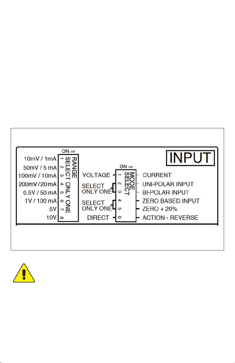
Note: Instrument is factory calibrated for 4 to 20 mA Uni-Polar
Direct-Acting Input and 4 to 20 mA Uni-Polar utput. Any change
from this default condition may require field re-calibration to ensure
accuracy of zero and span adjustments.
pecifications
Power Supply: 85 to 265 VDC/VAC, 50 to 400 Hz.
Isolation: 1500 VAC.
Ambient Temperature Range ( perating): 0 to 50°C (32 to 131°F).
Linearity: 0.1%.
Drift: ±0.02% per °C typical, ±0.05% maximum.
Maximum Current utput Load: 600 ohms.
Maximum Voltage utput Load: 20 mA (500 ohms).
Input Impedence – Current: 10 ohms.
Input Impedence – Voltage: 1 Megohm.
Figure 5: Calibration adjustment
location

Artisan Technology Group is your source for quality
new and certied-used/pre-owned equipment
• FAST SHIPPING AND
DELIVERY
• TENS OF THOUSANDS OF
IN-STOCK ITEMS
• EQUIPMENT DEMOS
• HUNDREDS OF
MANUFACTURERS
SUPPORTED
• LEASING/MONTHLY
RENTALS
• ITAR CERTIFIED
SECURE ASSET SOLUTIONS
SERVICE CENTER REPAIRS
Experienced engineers and technicians on staff
at our full-service, in-house repair center
WE BUY USED EQUIPMENT
Sell your excess, underutilized, and idle used equipment
We also offer credit for buy-backs and trade-ins
www.artisantg.com/WeBuyEquipment
REMOTE INSPECTION
Remotely inspect equipment before purchasing with
our interactive website at www.instraview.com
LOOKING FOR MORE INFORMATION?
Visit us on the web at www.artisantg.com for more
information on price quotations, drivers, technical
specications, manuals, and documentation
Contact us: (888) 88-SOURCE | sales@artisantg.com | www.artisantg.com
SM
View
Instra