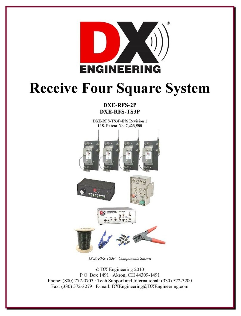
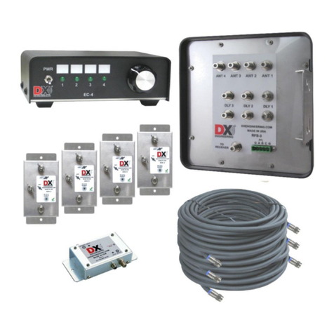
DX Engineering DXE-R4S-SYS-V3 User manual

Receive Four Square System
DXE-R4S-SYS-V3
U.S. Patent No. 7,423,588
DXE-R4S-SV3-INS rev.0
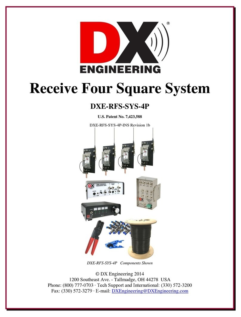
DXE-R4S-SYS-V3 Components Shown
© DX Engineering 2022
1200 Southeast Ave. - Tallmadge, OH 44278 USA
Phone: (800) 777-0703 ∙ Tech Support and International: (330) 572-3200
E-mail: [email protected]

2
Table of Contents
Introduction
3
Default Jumper Configuration Settings
18
System Overview
4
Diagram 1 - Default Configuration
19
Features
4
Optimizing the Array
20
Additional Parts Required
5
Operation
20
Example of Array Performance
5
Normal Receive Four Square Operation
21
Site Selection
7
Receive Four Square Troubleshooting
21
Proximity to Transmit Antennas
7
Topographical Considerations
8
Site Selection in Relation to Noise Sources
8
Ground System
9
Appendix A - Alternate Configurations
26
Lightning Protection
9
Supplying Power Using the Feedline
26
Sizing the Array
10
Directional Control Using the Feedline
27
Four Square Layout
11
Diagram 2 - Alternate Configuration
28
System Operational Overview
12
Diagram 3 - Alternate Configuration
29
Installation
12
DXE-RFS-3 and Active Element Power
30
Active Antenna Elements
13
Directional Control
30
Active Antenna Feedlines
14
Internal Jumper Selection
30
Delay Lines
14
Default Jumper Configuration
31
Control and Power Connections
16
Technical Support and Warranty
32
Default Configuration
18
Figures
Figure 1 - Site Selection Clear Distance
7
Figure 2 - Layout of the DXE-R4S-SYS-V3 Four Square System
11
Figure 3 - Array Diagonal Dimension
15
Figure 4 - Jumper Locations showing Default Settings
19
Tables
Table 1 - Array Safety Distance Minimums at 1500 watts
8
Table 2 - Array Side Lengths
10
Table 3 - Examples of DLY3 Required Length
15
Table 4 - BCD Directional Control Matrix, “1” Equals +12 Vdc (Default)
27
Table 5 - Differential Voltage Control Matrix
28

3
Introduction
DXE-R4S-SYS-V3 - Complete Receive Four Square Array Package
Complete Receive Four Square Array Package
W8JI design RFS-3 array controller
Four DXE-RSEAV-1 Antennas with state-of-the-art DXE-AVA-3 Active Matching Units
Optimized 160-40 meters with 70ft. element side spacing; functions 100 kHz to 30 MHz
Excellent directivity in a small space and better signal-to noise ratio than transmit arrays and
other receive arrays
Switchable in four 90 degree spaced directions
Reduced susceptibility to high angle signals compared to EWE, Flag, Pennant, or K9AY
arrays
Low current DC powered control console allows system operation without AC power mains
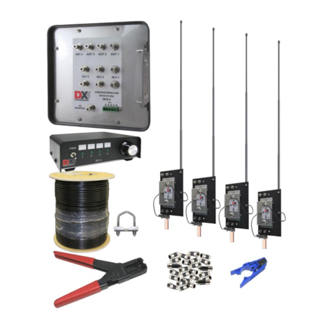
DXE-R4S-SYS-V3 (U.S. Patent No. 7,423,588) is the complete Receive Four Square Array
Package which includes:
(1) DXE-RSEAV-4 Receive Short Element Active Vertical Antennas (4) w/ Internal
Element Grounding Relays
(1) DXE-EC-4 Four Position BCD
Control Console
(1) DXE-RFS-3 Receiving Four
Array Controller
(1) DXE-RG6UFQ-1000 CATV RG6 Style
Coaxial cable, 75 Ω, RG6 Quad Shield,
Flooded for Direct Burial, 1000' Spool
(1) DXE-CPT-659 CATV, RG6
and RG-59 Coaxial Cable Stripper,
Includes 1 Replacement Blade
(1) DXE-EX6XL-25 75 ΩQuad Shield Coaxial
Cable Compression F Connectors for
DXE-RG6UFQ RG6 Cable, 25 pack
(1) DXE-SNS-CT1 Crimp Tool for Type F
75 ΩCoaxial cable Compression Connectors

4
System Overview
The DXE-R4S-SYS-V3 is an advanced four square receiving system that uses four symmetrically
spaced elements to provide switching for a 4-direction receiving antenna system. This unique
system uses time delay phasing rather than the single band phase shifting used in traditional four
squares. When used with active receive elements, this time delay phasing scheme provides the
correct phase relationship across a wide frequency range producing useful front-to-rear ratio (F/R)
response over octaves of bandwidth.
This system uses directionally-optimized time delays to produce wider and deeper rear nulls. Wide
null areas and a narrow main lobe greatly reduce noise and undesirable signals.
The system is more reliable than a conventional transmitting four square system in receiving
applications. Most transmitting four squares use large, exposed open-frame relays which can
become contaminated or corroded. This system uses sealed relays; contact size is optimized for
receiving applications.
Features
Advantages of the DXE-R4S-SYS-V3 Receive Four Square Antenna System over other receiving
arrays include:
Seamless stainless steel RFS-3 enclosure, for enhanced weather resistance
Reduced susceptibility to high angle signals compared to EWE, Flag, Pennant, and K9AY
antennas
Excellent directivity in a small space for better signal-to-noise ratio
Switching of four 90 degree spaced directions
Directivity over a very wide frequency range using DX Engineering’s Active Receive
Antennas
Requires less space than a Beverage antenna. Active elements need only a minimal ground
system
Easier to deploy and maintain than a four direction Beverage antenna system
Using active elements, system allows close proximity to transmit antennas using
transmit/receive sequencer
Enhanced relay contact reliability
Low current DC powered control console allows system operation without AC power mains
This manual will describe the DXE-R4S-SYS-V3 Receive Four Square System in detail.
The DXE-R4S-SYS-V3 is a sophisticated system that requires critical control and
operational voltage and three specialized delay line connections with lengths that
are dependent upon band coverage optimized four square size.
Failure to make quality feedline and delay line connections can cause the entire
array to not function correctly or to perform poorly.

5
Additional Parts Required, Not Supplied with the DXE-R4S-SYS-V3
Four Conductor Power and Control Cable for RFS-3
Four conductor cable (3 plus ground), 22 gauge minimum is required. Economically priced
COM-CW-4 is a four conductor control wire which may be used.
Ground Rods (5/8" x 4 to 6 feet) for the Active Receive Vertical elements and the RFS-3 unit.
Mounting pipe for the DXE-RFS-3. The DXE-RFS-3 unit has been pre-drilled to accommodate
up to a 2 inch OD pipe using the included DXE-SSVC-2P Stainless Steel V-Bolt Saddle Clamp for
1" to 2" OD pipe. If smaller pipe mounting is desired, the optional DXE-CAVS-1P V-Bolt Saddle
clamp can be used for pipe from 3/4" to 1-3/4" inches OD. Note: JTL-12555 Jet-Lube SS-30 Anti-
Seize must be used on all clamps, bolts and stainless steel threaded hardware to prevent galling and
to ensure proper tightening. The controller can also be mounted on a sturdy wooden post, but
provision for grounding the DXE-RFS-3 unit must be made.
Example of Array Performance
Dedicated receive antennas have better signal-to-noise ratios. Directing the antenna away from
noise sources or toward the desired signal path is the primary benefit. Antenna gain is a secondary
advantage. As frequency increases, the fixed array size becomes electrically larger in terms of
wavelength. The increased electrical spacing produces higher sensitivity (average gain) even though
front-to-rear ratio only changes slightly. On the low bands, once the receiving system limits on
external noise, antenna directivity (F/R) is the only thing that affects the signal-to-noise ratio.
An average Beverage antenna exhibits about -6 dB gain. You would need two reversible Beverage
systems to obtain 4-direction selectivity and you still would be limited to one or two bands. The
DXE-R4S-SYS-V3 system occupies less space, is much easier to install, is less conspicuous and
operates over a wider frequency range with similar or better performance.
A test array was constructed using DX Engineering Active Elements and a side length of only 35
feet. It showed excellent performance across a wide frequency range. This side length is optimal for
40 m, according to Table 2. The array functioned well from 3 MHz to 15 MHz. As shown, the
patterns stay clean with good directivity and front-to-rear performance. The elevation angle is 15
degrees for all patterns. On this size array, amplification was required below 3 MHz.
Note: The DXE-RFS Receiving system must be separated from transmitting or other
antennas and structures (particularly metal) by at least 1/2-wavelength. Less
separation may cause significant pattern distortion and the introduction of re-
radiated noise and signals into the system. This becomes apparent as reduced
front-to-rear directivity in one or more directions or a higher noise level.
In a different test array with 50 foot side lengths, optimum performance occurred between
3 and 4 MHz. Performance on 7 MHz was also excellent. Amplification was used below
2 MHz. The highest usable frequency was 10 MHz. This array also produced usable F/R ratios
down to the lower end of the AM broadcast band (600 kHz).

6
Increasing the array size increases its sensitivity on the lower frequencies, sliding the performance
curve toward the low frequencies and potentially eliminating the need for amplification.

7
Site Selection
Site selection is important. The DXE-R4S-SYS-V3 system can be positioned as close as 1/10
wavelength to transmitting antennas. The DXE-RSEAV-4 Active Elements are bypassed to ground
when power is turned off. A programmable sequencer, such as the optional DXE-TVSU-1B will be
required with the DXE-R4S-SYS-V3, for an array located within 50 ft. of transmitting antennas.
Significant pattern distortion or coupling may result from close spacing. To prevent pattern
degradation, reception of re-radiated electrical noise or other interference, separation of 1/2
wavelength (at the lowest operating frequency) is ideal. See Figure 1. The goal is to do the best you
can by balancing all the factors.
The minimum distance to any transmitting antenna from the Four
Square perimeter is 1/10 wavelength. Greater than 1/2 wavelength is
the minimum distance that will limit coupling to other antennas and
the introduction of broadband re-radiated noise and signals.
Figure 1 - Site Selection Clear Distance
Proximity to Transmitting Antennas
The DXE-RSEAV-4 Active Elements and your transmitting antenna need only minimal physical
separation to maintain safe power levels when the optional DXE-TVSU-1B sequencer is used. With
1500 watts output and a unity gain (0 dB) antenna, the closest active element can be 1/10
wavelength from the transmitting antenna at the lowest transmitting frequency. Doubling the
protection distance quadruples safe power levels. See Table 1.

8
For example, transmitting legal-limit power output (1500 watts) into an ideal four square
transmitting antenna produces about 6,000 watts ERP (6 dB gain). Because of the increased radiated
power level, nearly 1/2 wavelength minimum spacing between the transmitting and receiving
antenna arrays is required, even when using the optional DXE-TVSU-1B Time Variable Sequencer
Unit to remove power from the active receive antennas used in the receive four square array.
Table 1 indicates minimum safe distances for the sequenced active array from transmitting antennas
with 0 dB, 3 dB and 6 dB gain (ERP) using a 1500 watt transmitter. Your actual system may vary
according to location and proximity to various objects.
Band
Unity (0 dB) Gain
3 dB Gain (2x)
6 dB Gain (4x)
160m (1.8 MHz)
55 feet
110 feet
220 feet
80m (3.5 MHz)
28 feet
56 feet
112 feet
40m (7.0 MHz)
15 feet
30 feet
60 feet
Table 1 - Array Safety Distance Minimums at 1500 watts
For any DX Engineering Receive Four Square, using the optional DXE-TVSU-1B Time Variable
Sequencer Unit to sequence Active antenna power will ensure that transmitted energy will not cause
damage to the receive system.
Topographical Considerations
Flat land is best. Erecting the receiving array on sloped land or steep hills may degrade
performance. To avoid pattern degradation, antenna elements must have reasonably similar
elevations. It's recommended the ground height difference between any element in the array be less
than 10% of the array diameter. For example, a 60 foot diameter array should be within six feet of
level. Every effort should be taken to make the elements symmetrical. Elements should all be
identical in construction and grounding, and should be mounted above any standing water line but
as close to the ground as possible. In general, the system will not be affected by trees or foliage as
long as the foliage does not contact the element. Ideally, in important receiving directions, there
should be a clear electrical path for at least 1 wavelength. The site should allow a ground system to
be evenly distributed around the antennas, if one is required.
Site Selection in Relation to Noise Sources
Because the array is directional across its corners, use this example as a guide: If you have a noise
source and if your primary listening area is northeast, locate the array northeast of the dominant
noise source. This ensures the array is looking away from the source of noise when beaming in the
primary listening direction. The second-best location for the array is when the noise source is as far
as possible from either side of the array. If you look at patterns, the ideal location for the array is
one that places undesired noise in a deep null area.
If your location doesn’t have the usual noise sources (power lines, electric fences, etc.), locate the
array so that your transmitting antennas and buildings are off the back or side of the receiving array.

9
Noise that limits the ability to hear a weak signal on the lower bands is generally a mixture of local
ground wave and ionosphere propagated noise sources. Some installations suffer from a dominant
noise source located close to the antennas. Noise level differences between urban and rural locations
can be more than 30 dB during the daytime on 160 meters. Nighttime can bring a dramatic increase
in the overall noise level as noise propagates via the ionosphere from multiple distant sources. Since
the noise is external to the antenna, directivity can reduce noise intensity.
Consider these things about noise sources:
If noise is not evenly distributed, performance will depend on the gain difference between
the desired signal direction (azimuth and elevation) and average gain in the direction of
noise.
If noise predominantly arrives from the direction and angle of desired signals (assuming
polarization of signals and noise are the same) there will be no improvement in the signal-to-
noise ratio.
If the noise originates in the near-field of the antenna, everything becomes unpredictable. This is a
good case for placing receiving antennas as far from noise sources (such as power lines) as possible.
Ground System
The four DXE-RSEAV-1 Active Elements work well with just a single 6’ x 5/8” copper ground rod
used as the ground mount. A separate mounting pipe can be used with optional clamps as the
element ground if the pipe is an adequate ground. Depending on soil conductivity, you can expect
better performance with multiple ground rods spaced a few feet apart. Increasing ground rod depth
beyond 5 feet rarely improves RF grounding because skin effect in the soil prevents current from
flowing deep in the soil. Avoid ground rods less than 5/8" OD. A good ground system improves the
array performance and enhances lightning survivability. It is important that each ground system be
the same for each active antenna in the array.
You can test ground quality by listening to a steady local signal. Attach 15 feet of wire laid in a
straight line (away from the coaxial feedline) to the initial 4 foot to 6 foot ground rod. If you
observe a change in signal or noise level, you need to improve the ground. A second rod spaced a
few feet away from the first one may correct the problem or 10 to 12 ground radials, each 15 feet
long, should provide a sufficient ground system for most soil conditions. If a good ground cannot be
established, use an optional DXE-RFCC-1 Receive Feedline Current Choke that will further
decouple the feedline from the antenna and reduce common mode current and associated noise from
the feedline.
Lightning Protection
While amateur radio installations rarely suffer damage from lightning, the best protection is to
disconnect electrical devices during storms. The key to lightning survival is to properly ground
feedlines and equipment and to maintain the integrity of shield connections. A proper installation
improves lightning protection and enhances weak signal receiving performance.
10
Consult lightning protection and station grounding information in the ARRL handbooks, or by
referring to the NEC (National Electric Code). The DX Engineering website also has technical and
product information listed under “Lightning Protection and Grounding.”Use lightning surge
protectors for the coaxial cable feedline and control lines.
Sizing the Array
When using active elements, the array side length can be as small as 1/10 wavelength and up to
about 1/2 wavelength on the highest frequency to be used. Sizes below 1/10 wavelength result in
unusable array sensitivity in the most desired bands. Making side lengths larger than 1/2 wavelength
on the highest frequency will split the main lobe and cause pattern and front-to-back degradation.
Determine the size of the array by considering the availability of appropriate space, frequency
coverage desired and the near proximity to undesirable noise sources, transmitting antennas and
other structures.
If there are no space constraints, follow the array side length recommendations in Table 2 for
excellent performance. Side lengths longer than the optimal lengths shown will move the peak
sensitivity of the array toward the lower frequency. For example, if you are most interested in 160m
performance with occasional use on 80m, make the side lengths longer than the optimal 98 feet
shown for 160m and 80m. This will improve 160m performance, reduce sensitivity on 80m
somewhat, but less than sizing the array exactly for 160m.
Band
Freq. - MHz
Optimal Side
Length in Ft
Min. Side
Length in Ft
Max. Side
Length in Ft
160
1.83
135
54
270
80
3.60
70
28
140
40
7.10
35
14
70
160, 80
1.83, 3.60
98
40
192
80, 40
3.60, 7.10
50
20
98
160, 80, 40
1.83, 3.60, 7.10
70
28
137
Table 2 - Array Side Lengths
If you have limited space, a carefully installed and amplified DXE-RFS can be used on multiple
bands with very small side lengths. At smaller side lengths, careful construction using precise
measurements is critical. On this type of fixed-size array, as frequency is decreased, the array signal
output decreases along with array sensitivity. Eventually the received ambient noise signal level
will decrease to a point where it is below your receiver’s noise floor. This comes from two effects:
Elements become electrically shorter, reducing element sensitivity
Element spacing becomes smaller in electrical degrees, reducing array sensitivity
Side lengths at 1/10 wavelength on 40 m would only be 14 feet. Although usable, amplification
would be required. In addition, the construction of a very small array is extremely critical. Side
lengths must be perfectly symmetrical. The delay lines must be directly measured for electrical
length and cut to exact lengths. The ground system must be effective. Even at this small spacing, the
array will have useful front-to-rear performance and directivity!

11
Four Square Layout
The array antenna elements should be arranged in a square, use Table 2 for guidance in choosing
the best combination of frequency coverage and side length dimensions.
The diagonal corners of the square should point in the most desirable receiving directions.
Element 1 is the default forward element, Element 3 is the rear or null element
Performance of the RFS-3 can noticeably decrease if structures radiating even small
amounts of noise or signals are within 1-wavelength of the array
Measure side-to-side and then corner-to-corner to ensure the element locations are square
Normally the RFS-3 phasing unit is installed near the center of the four array elements,
above any standing water, with the connector side facing down. The placement of the RFS-3
unit is not critical, however, the feedlines to each of the active elements must be equal in
length
If you mount the RFS-3 on a wood post, it should be grounded to a separate ground rod
Figure 2 - Layout of the DXE-R4S-SYS-V3 Four Square System
System Operational Overview
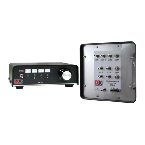
The DXE-R4S-SYS-V3 system is comprised of the DXE-EC-4 BCD Control Console and the
DXE-RFS-3 Control Unit. These units interconnect and work together using factory default
settings.

12
The DXE-EC-4 BCD Control Console supplies the nominal +12 Vdc operational voltage as well as
the +12 Vdc BCD control voltage. The operational voltage powers the DXE-RFS-3 Control Unit
which subsequently powers the active receive elements. The BCD switching voltages cause the
DXE-RFS-3 to change the receiving direction of the array.
The DXE-EC-4 Control Console is configured by default to output the BCD control voltages
needed by the DXE-RFS-3. The default direction for the array (toward Element 1) is selected when
LED 1 on the DXE-EC-4 is illuminated. When positions 2 to 4 are selected on the EC-4, the array
switches directions. Refer to Diagram 1for default connection details.
The DXE-RFS-3 distributes the operating power to the active elements through the individual
element feedlines. The active elements do not work without power. Cutting power to the
DXE-RFS-3 also cuts power to the active elements which causes the DXE-AVA-3 to ground the
vertical element. Operating with the optional DXE-TVSU-1B Sequencer (inserted into the EC-4
"C" to the RFS-3 "C" terminal) makes this power switching function automatically.
An alternate configuration (refer to Appendix A) which uses the feedline coaxial cable for either
the operational power or the directional control voltages, can be used. This configuration requires
internal jumper changes in the DXE-RFS-3, along with additional hardware to couple the proper
voltage to the feedline. For directional control through the feedline, the DXE-RFS-3 requires +12
Vdc, ─12 Vdc and 12 Vac. The DXE-FVC-1 Voltage Coupler can be used to supply these voltages.
In any alternate configuration, do not use coaxial cable or other conductor for more than one
simultaneous use. Refer to Diagram 2 for connection details of one of several alternate
configurations.
The only reason for using an alternate configuration is to make use of existing 2 or 3 conductor
control cable. Otherwise inexpensive four conductor control cable (COM-CW-4) and the default
configuration is recommended.
Installation
The DXE-RFS-3 Control Unit can be mounted to a galvanized pipe driven
into the ground. The DXE-RFS-3 unit has been pre-drilled to
accommodate up to a 2 inch OD pipe using the included DXE-SSVC-2P
Stainless Steel V-Bolt Saddle Clamp for 1" to 2" OD pipe. If smaller pipe
mounting is desired, the optional DXE-CAVS-1P V-Bolt Saddle clamp for
pipe from 3/4" to 1-3/4" inches OD is recommended. The controller can
also be mounted on a sturdy wooden post, but provision for grounding the
DXE-RFS-3 unit must be made. Note: JTL-12555 Jet-Lube SS-30 Anti-
Seize must be used on all clamps, bolts and stainless steel threaded hardware to prevent galling and
to ensure proper tightening.
The DXE-RFS-3 is designed to be used with the DX Engineering Receive Short Element Active
Vertical Antennas. It can also be used with passive elements for a dedicated mono-band array. The
user manual included with the DXE-RSEAV active elements has instructions for assembly and
installation. As noted in that manual, the active elements should be installed as close to the ground

13
as possible but above any high water line. Ground the ANT–(negative) terminal to an adequate
ground.
Station Feedline, Active Antenna Feedline and Delay Lines
The weakest link in an antenna system, such as the DXE-R4S-SYS-V3, is often the coaxial cable
connections. All connections must be high quality and weather tight to prevent contamination and
corrosion, which can cause the feedline impedance to change. This can affect the signal-to-noise
ratio and the directivity of the array. In addition, the DXE-RFS-3 uses the shield as a ground return
path for the active element power.
Note: The total loop resistance of the ground path must be under 30 Ω for reliable operation.
If the resistance of the shield increases due to contamination, the active elements may not function
properly. Any splices in the feedline should be high quality and entirely weather tight. Do not use
splices in the delay line cables. The DXE-R4S-SYS-V3 system has been designed to use only 75 Ω
coaxial cable.
Included with the DXE-R4S-SYS-V3 package is high quality, flooded 75 ΩRG6U quad shield type
coaxial cable. The DXE-RG6UFQ-1000 flooded coaxial cable automatically seals small accidental
cuts or lacerations in the jacket. Flooded coaxial cable also prevents shield contamination and can
be direct-buried.
Included with the DXE-R4S-SYS-V3 package is the coaxial cable preparation tool, part number
DXE-CPT-659, that readies the coaxial cable for connectors in one operation and comes with an
extra cutting cartridge. To ensure weather tight connections, use DXE-EX6XL-25 compression
style F connectors are also included. DXE- EX6XL-25 contains 25 compression F connectors,
enough for the entire array plus some spares. The compression F connectors cannot be installed
with normal crimping tools or pliers, so you also receive the installation tool DXE-SNS-CT1, from
DX Engineering with the DXE-R4S-SYS-V3 package for proper connector installation.
Active Antenna Feedlines
Use the included 75 Ω coaxial cable to make F connector assemblies to run from each antenna
element to the DXE-RFS-3. The four feedlines from the DXE-RFS-3 phasing unit to the active
elements can be any length needed to accommodate the size of the array, but they must all be the
same length, velocity factor and type. Note the orientation and numbering of the elements by
using Figure 2.Be sure the appropriate antenna element is connected to the proper ANT connector
on the phasing unit. The default (zero control voltage) forward direction is towards Element 1.
Element 3 is the default rear or null direction.
Delay Lines
The DXE-RFS-3 uses a time delay system, not a traditional phasing system. Delay line lengths are
dictated by array dimensions rather than operating frequency. This results in phase being correct for
a rearward null at any frequency. This system is especially effective when used with DX
Engineering DXE-RSEAV-4 active vertical elements. User-supplied passive elements can also
provide exceptional performance for single band operation where high dynamic range is required.

14
The DXE-RFS-3 phasing unit has three sets of delay line connections marked DLY1, DLY2 and
DLY3. Each of these connection pairs will have a specific length of coaxial cable acting as a jumper
between the two connectors. Jumper electrical length is critical. Careful measurements and the use
of 75 Ωcoaxial cable (included in this package system) with a known Velocity Factor (VF) is very
important.
If you are not using the included DXE-RG6UFQ-1000 quad shield coaxial cable, keep in mind that
solid Teflon®or polyethylene dielectric coaxial cable has a VF of approximately 0.66. Foamed
coaxial cable cables typically range anywhere between 0.75 and 0.90 VF, depending on the ratio of
air-to-dielectric material in the cable core. If you do not know the VF of the coaxial cable you are
using, you must directly measure the electrical length of the coaxial cable you have or obtain cable
with a known VF. The included DX Engineering DXE-RG6UFQ-1000 75 Ω quad shield coaxial
cable has a nominal VF of 0.82. For best performance, the coaxial cable for the delay lines should
be from the same batch or spool.
The first step is to determine the required electrical length of DLY3. This is based on the corner-
to-corner or diagonal distance between two diagonal corner elements of the square forming the
array. You can directly measure this distance, or it can be calculated by multiplying the side length
of the array by 1.4142. The electrical length of delay line DLY3 should be slightly shorter than the
actual physical distance between the two diagonal corners of the array. An electrical length 95% of
the physical distance works well (diagonal distance times 0.95). Table 3 shows these calculations
for three common side lengths.
Side Length in
Feet
Diagonal
Physical Length
in Feet
Factored 0.95
Electrical Length
in Feet
DLY3 Physical Length
in Feet (0.82 VF)
135 (160m)
190.9
181.4
148.8
98 (160m & 80m)
138.6
131.7
108.3
70 (80m)
99.0
94.0
77.1
Table 3 - Examples of DLY3 Required Length
After calculating the required electrical length, you must include the VF of the coaxial cable being
used when determining the correct physical length of DLY3. Multiply the factored electrical length
by the VF. The result is the correct physical length for DLY3. See Figure 3 and the sidebar for an
example. Note: These calculations are in feet, not feet and inches.
Figure 3 - Array Diagonal Dimension
To find the physical length of DLY3, calculate the
diagonal length of the array by either directly
measuring the diagonal or by multiplying the array side
length by 1.4142. DLY3 will be significantly shorter
than the actual physical length. The diagonal length is
first multiplied by 0.95. This gives the factored
electrical length for DLY3. Next, multiply the DLY3
electrical length by the VF of the delay line coaxial
cable. The result is the correct physical length for
DLY3.

15
For Example: An array with 90 foot side spacing, the diagonal length is 127.3 feet. The 0.95
factored physical length for DLY3 electrical length is 120.9 feet. Multiply 120.9
feet. by 0.82 (the VF of DX Engineering 75 Ω quad shield coaxial cable).
The correct physical length for DLY3 is 99.14 feet, or 99 feet, 1-5/8 inches.
Delay lines DLY1 and DLY2 must be half the length of DLY3. Make DLY1 and DLY2 as close
to half the physical length of DLY3 as possible. To avoid performance degradation due to
inconsistent coaxial cable construction, all the delay line coaxial cable should be cut from the same
spool.
Delay line cables can be neatly coiled in a 1-1/2 foot diameter coil. Support the weight of the cables
by taping or securing them to the support pole or mast rather than allowing them to hang from the
connectors.
It is important to use 75 Ωfeedline to the operating position from the DXE-RFS-3. Do not use
amplifiers, combiners, filters or splitters that are not optimized for 75 Ωsystems.
Control and Power Connections
If you have the DXE-R4S-SYS-V3 system, with the DXE-EC-4 Control Console, no other
equipment is needed for powering the DXE-R4S-SYS-V3, the active elements or controlling the
receive direction of the DXE-R4S-SYS-V3. The DXE-R4S-SYS-V3 has been factory-set to work
with the DXE-EC-4 using four conductor control cable such as COM-CW4.
J12 is the 5-terminal connector plug on the front panel of the DXE-RFS-3. It is labeled G A B C G.
The DXE-RFS-3 uses a two part green connector and the top part can be removed by pulling it
straight off. This will allow easier wire replacement or servicing as needed. When pushing the
connector back in place, ensure you press straight inward.

16
The DXE-EC4 uses an internal terminal plug labeled “G 1 2 3”.
DXE-EC-4
DXE-RFS-3
G
to
G
1
to
A
2
to
B
3
to
C
Direct Wire connections between the DXE-EC-4 and DXE-RFS-3
For systems that have 1/2-wavelength or greater spacing between the receive four square array and
any transmitting antenna, the optional TVSU-1B is not be needed. The wiring diagram above shows
wiring between the DXE-EC-4 and the DXE-RFS-3. If you are using the optional DXE-TVSU-1B,
the wiring connections are shown in Diagram 1 - Default Configuration.
Control lines (usually BCD ) can normally use good quality CAT5e cable (4 twisted pairs of 24
AWG wire) for runs up to 1000 feet. Typical DX Engineering BCD control lines requirements are
+12 VDC at 25 milliamps.
Depending on the number of control lines needed (usually 3 or 4) you can double up the twisted
pairs of CAT5e cable, or use control wire that is at least 22 AWG, allowing runs up to 1500 feet. If
you use a cable with more conductors, it is a good idea to tie the unused conductors to ground.
For longer runs of control cable, use a line loss calculator to ensure you supply the proper control
levels needed.
Approximate BCD Control Line Lengths.
Minimum Copper
Wire Gage (AWG)
Length
24
1,000 feet
22
1,500 feet
20
2,000 feet
Active antenna circuitry needs a good voltage supply to operate properly. When supplying power to
an active antenna, you want to have +12 VDC, 40 milliamps at each active (under load).

17
CAT5e cable is not recommended when making long runs to power an active antenna since the line
loss in CAT5e cable may not supply the proper operational voltages required for active antennas.
Depending on the required length of your power wire, you will want to use a line loss calculator
(voltage drop with various wire gages) to ensure your power supply (normally +13.6 well filtered
DC) will supply a minimum of +12 VDC, 40 milliamps at each active antenna (under load).
A DX Engineering 4 Square or 8 Circle will require approximately 250 milliamps (only 4 actives
are powered at any one time).
When calculating line length, take into consideration the total number of active antennas being
powered at any one time in your line length calculations.
Approximate Active Antenna Power Line Lengths (4 active antennas on at any one time).
Minimum Copper
Wire Gage (AWG)
Length
18
300 Feet
16
500 feet
12
1,200 feet
10
2,000 feet
Default Configuration
The DXE-R4S-SYS-V3 default configuration, as shown in
Diagram 1, uses terminals A & B for the BCD directional
control interface and terminal C for operational and active
element power. The DXE-EC-4 provides the operational
power as well as the 2-bit BCD interface used for directional
control. A user-supplied 4-conductor cable is needed to
connect the DXE-RFS-3 and the DXE-EC-4 with the
optional DXE-TVSU-1B Time Variable Sequencer Unit
switching the active antenna power conductor.
The switch positions on
the DXE-EC-4 control
the directivity of the
received signal in the
DXE-R4S-SYS-V3.
As shown in the diagram
to the right, position one
favors the NE direction, position 2 favors the SE direction,
position 3 favors the SW direction and position 4 favors the NW
direction when the array is positioned as shown.

18
Diagram 1 –Default Configuration for the DXE-R4S-SYS-V3
Shown with optional items. Accessory DC power cables omitted for clarity.

19
Optimizing the Array
To determine if the antenna system output level is the limiting factor, tune the receiver to the lowest
band at the quietest operating time. This is usually when propagation is poor but some signals are
heard. Disconnect the antenna and set the receiver to the narrowest selectivity you expect to use.
Receiver noise power is directly proportional to receiver bandwidth (going from 2.5 kHz selectivity
to 250 Hz selectivity reduces noise by 10 dB). Connecting the antenna should result in a noticeable
increase in noise. If so, the array signal level is sufficient, then further optimization or amplification
is not be needed.
If the array is used only 160m or below, the Active Antenna internal gain jumper can be reset as
discussed shown in the DXE-AVA-3 manual. If the array still lacks sensitivity on the low bands,
then a preamplifier with high dynamic range can be used to compensate for the low signal level.
However, using a preamplifier when sufficient signal is already present may result in amplification
of the noise along with the signal. It is always best to use the least gain possible. Depending on
conditions, using a preamplifier can cause receiver overload; either use an input RF attenuator or
bypass the preamplifier.
The DXE-RPA-2 HF Preamplifier has better dynamic range than most receivers and can be used to
compensate for the decrease in array signal output. The DXE-RPA-2 preamplifier is automatically
bypassed when power is removed.
Operation
When using the DXE-RFS-3, positions 1 through
4 on the EC-4 BCD Control Box will phase the
appropriate active vertical elements to give you
excellent receiving capabilities.
The front to back signal to noise ratio of the active
vertical elements in the four phase array allow you
to not only enhance the desired received signal,
but also to decrease an unwanted receive signal by
selecting a position that will drastically reduce or
eliminate it.

20
Normal Receive Four Square Operation
When the Receive Four Square system is functioning properly, low or medium power daytime AM
Broadcast ground wave signals should be alternately attenuated or improved with directional
switching. However, strong sky wave signals arriving at high angles of propagation will show very
little signal level change as different directions are selected on the Receive Four Square.
Although some low band signals may be received at very low levels, they are heard more easily due
to far less noise received by the non-resonant array. If necessary, the use the DXE-RPA-2,
Receiver Preamplifier - an in-shack pre-amplifier with exceptionally low-noise and high dynamic
range characteristics. The DXE-RPA-2 will enhance the intelligibility of the weak DX signals,
without adding the noise that plagues many of the pre-amps that are built into modern transceivers.
The Receive Four Square array pattern is designed to enhance forward low angle signals, and reject
rearward and high angle signals. The Receive Four Square system provides superior signal-to-noise
results that allow you to hear signals that are impossible to copy on much noisier transmit antennas,
for greatly improved weak signal DX operations.
Receive Four Square Troubleshooting
There are several possible causes for a malfunction of a DX Engineering Receive Four Square
System. Testing the system is not difficult and can be completed in an hour or so. Separate circuits
for directional switching, Active Vertical Antenna power, and antenna phasing can each be affected
by a variety of cabling, connection and or component problems. If you are troubleshooting a new
system or using a replacement RFS-3 unit, check that the internal jumpers are set correctly for your
system control and voltage configuration.
Here are the most common causes of Receive Four Square malfunction, especially in a system that
was previously functioning properly:
Table of contents
Other DX Engineering Receiver manuals

DX Engineering
DX Engineering DXE-RFS-SYS-4P User manual

DX Engineering
DX Engineering DXE-RFS-TS2P User manual

DX Engineering
DX Engineering DXE-RCA8CB-SYS-4P User manual

DX Engineering
DX Engineering DXE-RFS-SYS-4S User manual

DX Engineering
DX Engineering DXE-RFS-2P User manual

DX Engineering
DX Engineering DXE-RFS-SYS-2P User manual

DX Engineering
DX Engineering DXE-NCC-2 User manual

DX Engineering
DX Engineering DXE-RFS-SYS-3P User manual