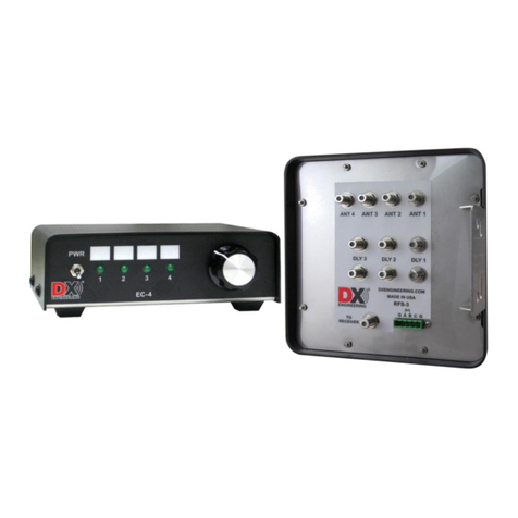
5
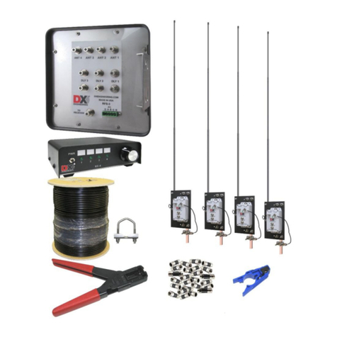
Additional Parts Required, Not Supplied with the DXE-RFS-SYS-4S
Four Conductor Power and Control Cable for RFS-3
Four conductor cable (3 plus ground), 22 gauge minimum is required. Economically priced
COM-CW-4 is a four conductor control wire which may be used.
Ground Rods (5/8" x 4 feet) for the Active Receive Vertical elements and the RFS-3 unit.
Mounting pipe for the DXE-RFS-3. The DXE-RFS-3 unit has been pre-drilled to accommodate
up to a 2 inch OD pipe using the included DXE-SSVC-2P Stainless Steel V-Bolt Saddle Clamp for
1" to 2" OD pipe. If smaller pipe mounting is desired, the optional DXE-CAVS-1P V-Bolt Saddle
clamp can be used for pipe from 3/4" to 1-3/4" inches OD. Note: JTL-12555 Jet-Lube SS-30 Anti-
Seize must be used on all clamps, bolts and stainless steel threaded hardware to prevent galling and
to ensure proper tightening. The controller can also be mounted on a sturdy wooden post, but
provision for grounding the DXE-RFS-3 unit must be made.
Example of Array Performance
Dedicated receive antennas have better signal-to-noise ratios. Directing the antenna away from
noise sources or toward the desired signal path is the primary benefit. Antenna gain is a secondary
advantage. As frequency increases, the fixed array size becomes electrically larger in terms of
wavelength. The increased electrical spacing produces higher sensitivity (average gain) even though
front-to-rear ratio only changes slightly. On the low bands, once the receiving system limits on
external noise, antenna directivity (F/R) is the only thing that affects the signal-to-noise ratio.
An average Beverage antenna exhibits about -6 dB gain. You would need two reversible Beverage
systems to obtain 4-direction selectivity and you still would be limited to one or two bands. The
DXE-RFS-SYS-4S system occupies less space, is much easier to install, is less conspicuous and
operates over a wider frequency range with similar or better performance.
A test array, constructed at DX Engineering using the DXE-ARAV4 Active Elements and a side
length of 35 feet, showed excellent performance across a wide frequency range. This side length is
optimal for 40 m, according to Table 2. The array worked from 3 MHz to 15 MHz. As shown on
the following page, the patterns stay clean with good directivity and front-to-rear performance. The
elevation angle is 15 degrees for all patterns. Amplification is required below 3 MHz.
Note: The DXE-RFS Receiving system must be separated from transmitting or other
antennas and structures (particularly metal) by at least 1/2-wavelength. Less
separation may cause significant pattern distortion and the introduction of re-
radiated noise and signals into the system. This becomes apparent as reduced
front-to-rear directivity in one or more directions or a higher noise level.
In a different test array with 50 ft side lengths, optimum performance occurred between
3 and 4 MHz. Performance on 7 MHz was also excellent. Amplification was used below
2 MHz. The highest usable frequency was 10 MHz. This array also produced usable F/R ratios
down to the lower end of the AM broadcast band (600 kHz).
