DX Patrol QO-100 User manual

QO-100 DX-Patrol Ground Station
An all-in-a-box station for easy QO-100 operation

V1.1 Page 2
1 Table of Contents
2 Main Characteristics: ........................................................................................................................ 3
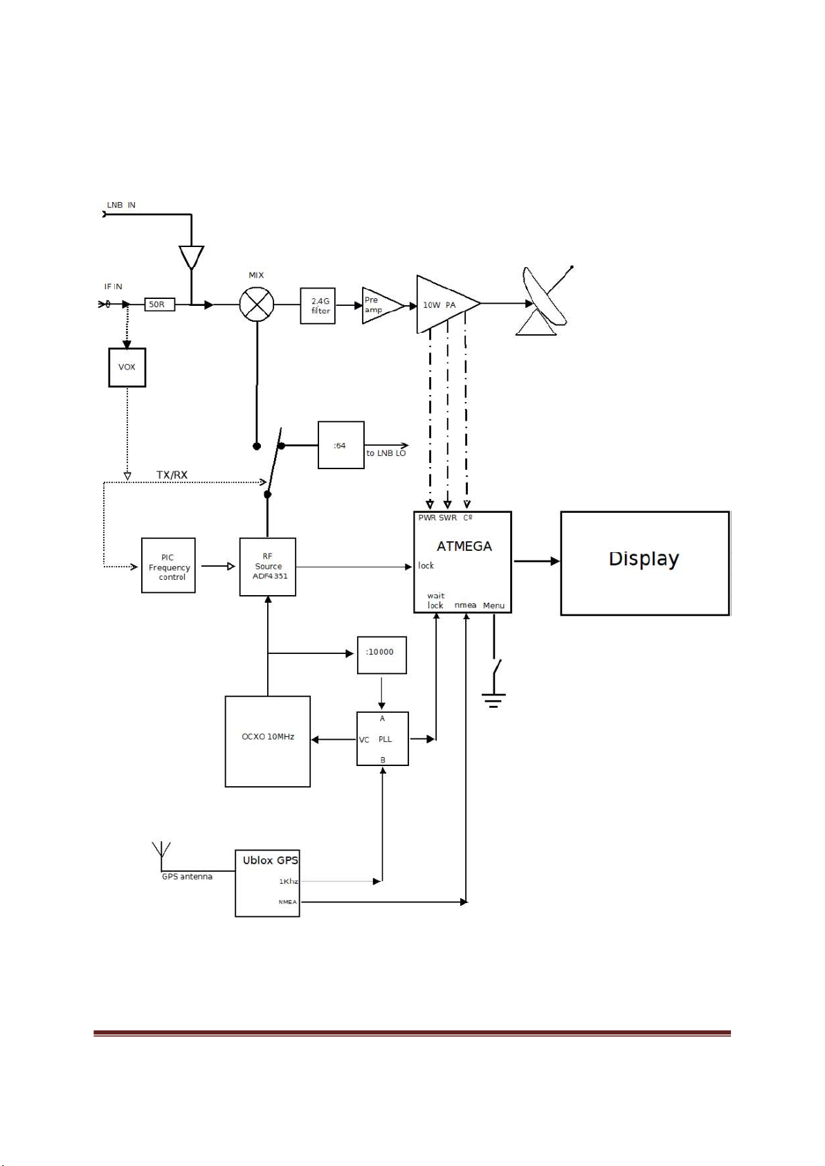
3 Simplified block Diagram .................................................................................................................. 4
4 General overview ............................................................................................................................. 5
5 Connecting the Ground Station ........................................................................................................ 6
5.1 Equipment needed: .................................................................................................................. 6
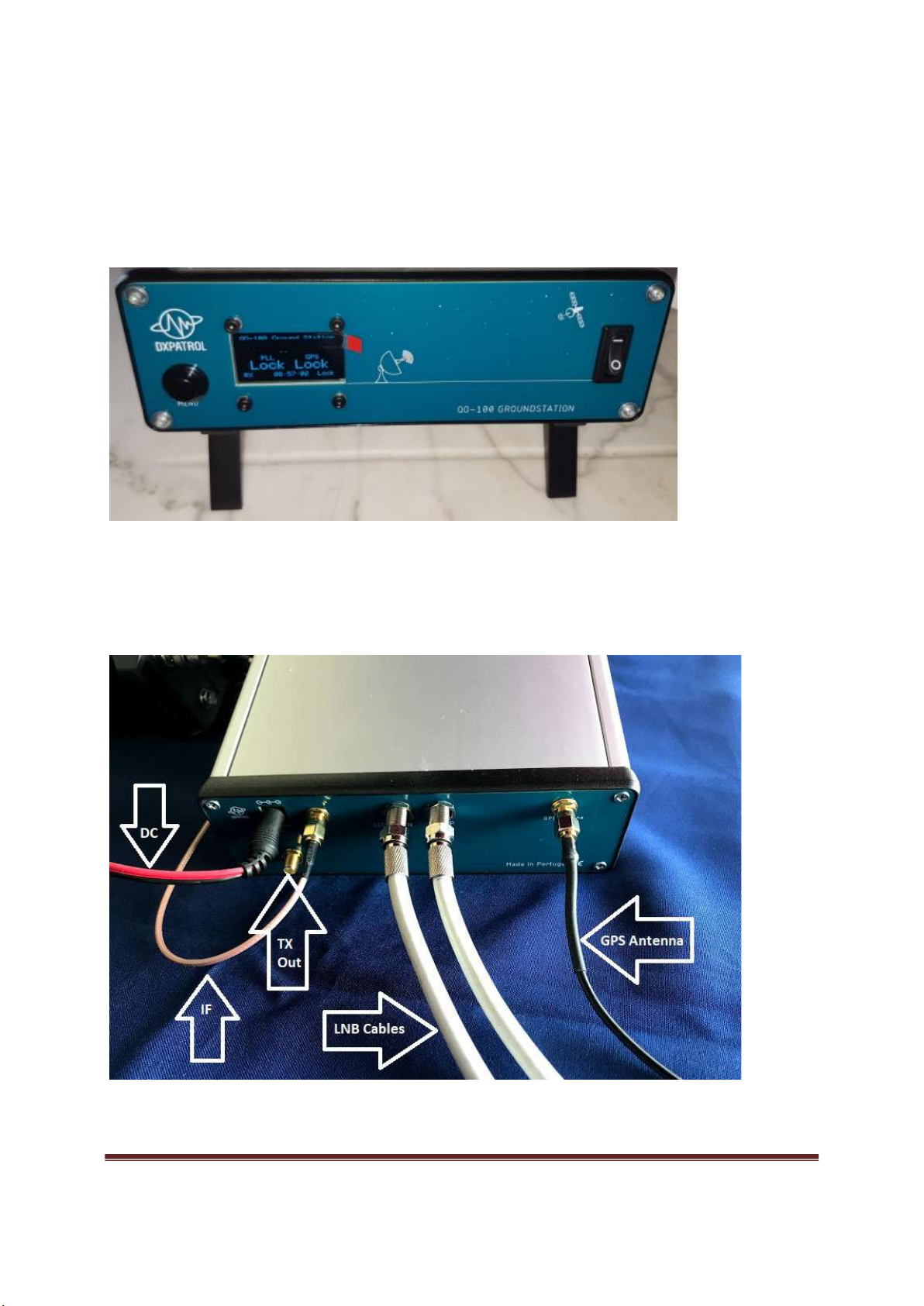
5.2 How to connect? ...................................................................................................................... 6
6 Operating the Ground Station .......................................................................................................... 7
6.1 Switch the Ground Station on with the switch on the frontpanel. ............................................. 7
6.2 Scrolling the menu .................................................................................................................... 7
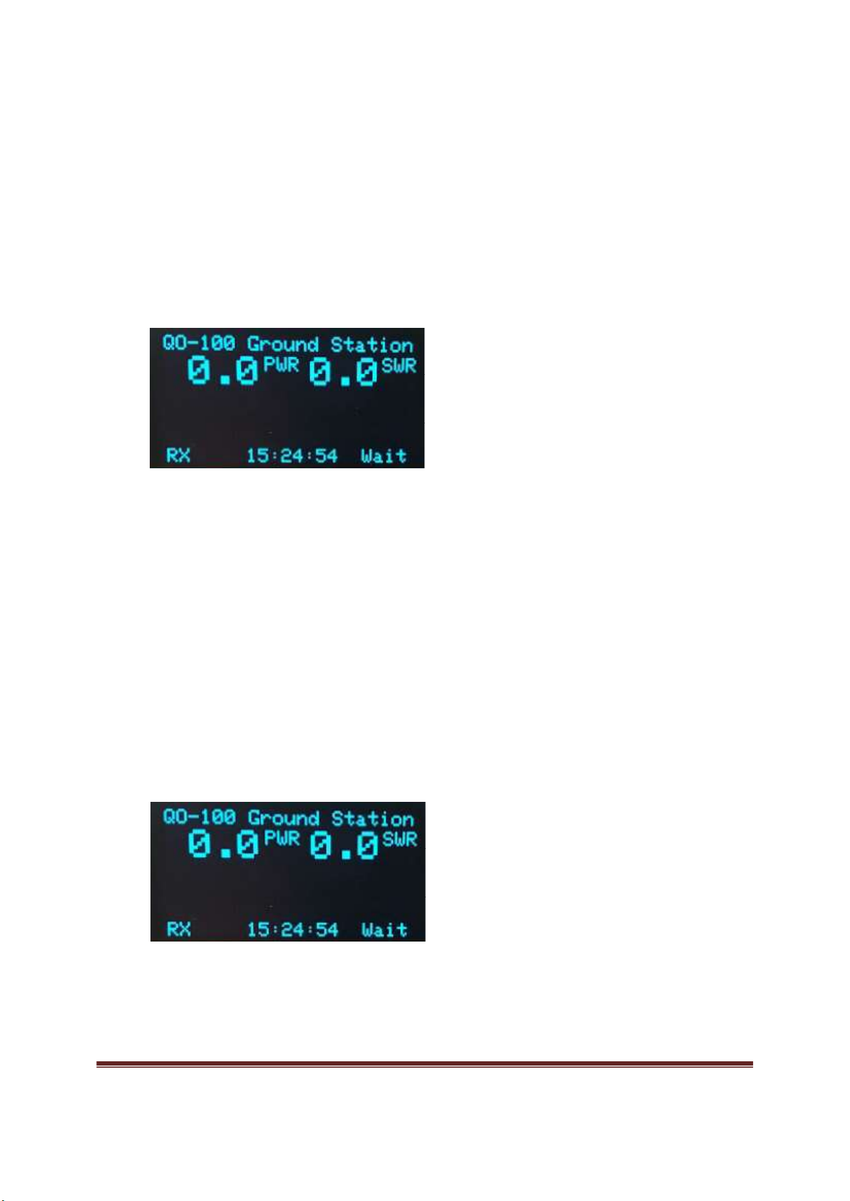
6.2.1 Welcome screen ............................................................................................................... 7
6.2.2 Satellite input power......................................................................................................... 8
6.2.3 Information menu ............................................................................................................. 8
6.2.4 GPS menu ......................................................................................................................... 9
6.2.5 Ground Station information .............................................................................................. 9
6.3 Ready for operation ................................................................................................................ 10
6.4 Transmitting ........................................................................................................................... 10
7 Adjustments ................................................................................................................................... 11
7.1 IF Levels.................................................................................................................................. 11
7.2 Power meter level .................................................................................................................. 12
8 Detailed views and schematic ........................................................................................................ 13
9 Included parts list ........................................................................................................................... 15
10 Available accessories .................................................................................................................. 16
11 Contact information ................................................................................................................... 17

V1.1 Page 3
2 Main Characteristics:
• Reception frequency: 10489.500 to 10490.000MHz;
• Transmission Frequency: 2400.000 to 2400.500 MHz;
• IF Frequency: 432.500 to 433.000 MHz;
(linear up and down converter, for both TX as RX);
• GPS Lock internal 10MHz reference;
• Maximum Output RF Power 10 W based on NXP MHR1008NT1;
• Factory set input power 250 mW * (*can be adjusted with R38);
• Maximum input RF 5W ( 500mW optimum drive);
• Auto TX and RX by vox PTT
• Supply voltage 12V to 14V;
• Thermal protection > 60º C;
• SWR protection > 1:3;
• High voltage input protection;
• Satellite Strength signal indication;
• Power output bar and Watt indication;
• SWR bar and ratio indication;
• Internal 3A fuse protection;
• NMEA GPS indication;
• Number of GPS satellites in range;
• GPS coordinates;
• QTH Locator presentation on screen;
• UTC clock and date;
• Mixer, Double Balanced Mixer ADE-35+

V1.1 Page 4
3 Simplified block Diagram

V1.1 Page 5
4 General overview
Front view
The Ground Station has 2 tilt feet on the bottom, front side, for easy access and use.
Left the menu buttom, next OLED screen and on the right the ON/OFF switch.
Rear view

V1.1 Page 6
5 Connecting the Ground Station
5.1 Equipment needed:
A power supply 12V or ( 13,8V) 5A minimum;
Two coaxial TV 75 Ohm cables for satellite LNB fitted with F connectors;
Low loss coax cable (50ohm) from RF out to patch/helix antenna.
.
5.2 How to connect?
WARNING
Never make these connections with Ground Station ON.
There is 12V Phantom Power on the cable and a short-circuit will happen if life wire touches the shield,
damaging the Ground Station .
1. Connect the Ground Station correctly to the LNB with 75 ohm cable with F connectors;
Cable 1 : LO UP to LNB´s input LO
Cable 2 : SIG IN to LNB´s SIG
2. Connect the GPS antenna to GPS input ( SMA connector);
GPS antenna must be outside with clear visibility to sky. The antenna is waterproof, but
will be good to fit it inside a plastic bag to avoid rain damage. In some cases it can work
on a window, even inside.
3. Connect IF to your UHF SSB with a 50 ohm coaxial cable fitted with a male SMA
connector;
4. Connect the OUT RF to the transmitting antenna with a 50 ohm low loss coaxial cable
5. Connect the 12V power supply (center pin is positive pin)

V1.1 Page 7
6 Operating the Ground Station
6.1 Switch the Ground Station on with the switch on the frontpanel.
When turning ON you will see for some seconds the Splash Screen Logo of Dxpatrol and
then the display will present a page as show in the picture below.
RX mode, no Power/SWR detected, Clock and Wait.
The clock is UTC time and it takes a few seconds to be visible. (only visible with GPS
satellites in range).
While the OCXO (oven-controlled crystal oscillator) is warming up, the WAIT indication is
flashing. This can take a few minutes.
6.2 Scrolling the menu
Pressing the Menu Button advances You in the menu, press and hold the button will freeze
the chosen menu page.
6.2.1 Welcome screen

V1.1 Page 8
6.2.2 Satellite input power
This page shows input satellite strength. This is shown in dBm and it's very useful to
point the dish and fine adjustment of LNB in the focal point.
6.2.3 Information menu
This page shows:
the input DC voltage;
PA temperature;
Internal LO source ADF4351 lock status;
GPS lock status (this can take a few minutes).

V1.1 Page 9
6.2.4 GPS menu
Overview of the GPS data.
Geographic Coordinates;
Date and UTC time;
Number of GPS in range;
WW QTH locator.
6.2.5 Ground Station information
Current FW version (August 2021)
Serial number.

V1.1 Page 10
6.3 Ready for operation
When both LOCK indications are shown on screen, you are ready to start using the QO-100
satellite.
Any UHF SSB radio as IF will receive very loud and clear satellite signals. Lower beacon should be
at 432.500 MHz and upper beacon should be at 433.000 MHz.
The Ground Station will receive the QO-100 very clearly with the included LNB with any dish,
even small ones as 30cm.
However, in transmission, to have a clear loud signal, you should use a minimum 60cm dish and
an efficient antenna feed, such as a Helix or a Patch antenna, low loss cable as short as possible
is preferred to feed the 2.4 Ghz up to the dish.
6.4 Transmitting
There is no need for any PTT, switch or cable (except for the coaxial cable from radio to Ground
Station) to activate the Ground Station into TX mode.
Even 250mW of RF is enough to trigger the VOX and switch to TX mode.
The TX indication will be visible, as well the Output Power in Watts and in a bar-graph.
Maximum power is 10 W output and SWR bar and ratio will be presented if reflected power is
detected. Alarm will display if SWR rises more than 1:3, to clear an SWR or Temperature Alarm,
press Menu button.

V1.1 Page 11
7 Adjustments
7.1 IF Levels
The set input level (factory setting) is 250mW.
For maximum versatility the required input power of the Ground Station can be adjusted on the
inside. The RX gain can be adjusted as well.
P38 sets the TX gain
R13 sets the RX gain level.

V1.1 Page 12
7.2 Power meter level
These are factory set and should not be adjusted without the proper external power meter equipment.
R59 sets the forward power level indicated on the OLED display.
R61 sets the SWR level indicated on the OLED display.

V1.1 Page 13
8 Detailed views and schematic
Inside views
Power amplifier on the bottom of the case
On the left the 12v->28volts convertor, on the right the top board holding the RF parts

V1.1 Page 14
PTT VOX circuit
The F6 on the PCB board can be used for PTT switching from the radio (requires soldering on the PCB)

V1.1 Page 15
9 Included parts list
Modified Dxpatrol LNB
Dxpatrol GPS + Glonass antenna

V1.1 Page 16
10 Available accessories
DXPATROL Helix QO-100 antenna

V1.1 Page 17
11 Contact information
Website www.dxpatrol.pt
Email: [email protected] or [email protected]t
Tel +351965626669
Table of contents