DXI MicroComm DXI MAI-125 User manual

MAI-125 Master Audio Interface
Document IM-MAI-125-2.2 © 1997 Harding Instruments - Printed in Canada
INSTALLATION MicroCommDXI
INSTRUCTIONS
1.Intent & Scope
This document describes the installation procedure for the MAI-125 Master Audio Interface.
2. Description
The MAI-125 Master Audio Interface connects to the intercom system via an SAB-100 station audio board. The
MAI-125 provides an audio communication channel from a master station to a DXI exchange. The MAI is usually
used in conjunction with other devices, such as touch screen monitors or switch panels, that can provide display
as well as control inputs to the DXI system.
The MAI-125 provides interface connectors for telephone handset, hookswitch, speaker, microphone, headset and
phantom powered microphone. A combination of these audio devices can be used. If more than one audio/input
device is connected to the MAI the hookswitch and speaker/headset switch will determine which speaker
receives audio and which microphone is active. If the hookswitch is off hook the speaker audio is connected to
the handset speaker and handset microphone audio is connected to the microphone audio lines. If the hookswitch
is on hook the speaker audio is connected to either the headset or handsfree speaker depending on the state of the
speaker/headset switch. If the speaker/headset switch is closed (corresponding to having a headset jack plugged
in) the headset microphone is active and the speaker audio is connected to the headset. If the hookswitch is on
hook and the speaker/headset switch is open then handsfree operation is possible with either an electret or
phantom microphone (but not both). The following table summarizes the operation of the hookswitch and
speaker/headset switch.
HEADSET
HANDS
FREE
HANDSET
HANDSET
ON
HOOK OFF
HOOK
CLOSED
OPEN
SPEAKER/HEADSET
SWITCH
HOOKSWITCH
The MAI-125 has provisions for several press-to-talk (PTT) inputs. The PTT switches can be used to control the
audio direction of half duplex calls. The PTT inputs appear on the main DB-25 connector, the handset connector
and the headset connector. Although all inputs are in parallel, and perform the same function, the additional PTT
inputs simplifies interfacing wiring. For example a PTT switch can be located in the handset, on a graphics panel,
or a footswitch. If more than one type of PTT switch is used a switch closure on any one of the switches will cause
the MAI-125 to transmit audio to the device being called.

MAI-125 Master Audio Interface
Page 2 Document IM-MAI-125-2.2
The MAI-125 provides a pair of contacts on the hookswitch connector that can be used for attaching a
microphone muting switch. If the muting switch is closed all of the microphone inputs connected to the MAI are
muted. This feature ensures that the operator can control the audio that is transmitted over an open audio circuit.
3. Wall Mounted MAI-125 Master Audio Interface
The wall mounted MAI-125 provides an intercom channel from audio devices to an exchange. The MAI-125 is
typically mounted under or inside a control console. Either #8 or #10 round head screws can be used to mount
the MAI.
Wall Mounted MAI-125

MAI-125 Master Audio Interface
Document IM-MAI-125-2.2 Page 3
Handset
Hookswitch
SPKR / MIC
Headset
Phantom
Powered
MIC
MicroComm DXI
Master Audio Interface
MAI - 125
1
1
1
1
1
ON
Fuse
Slow Blow
1 A Max
I /O Connector
14 25
113
6.00"
6.00"
1.80" 6.50"
9.00"
MAI Base Plate Showing Mounting Detail
Electrical connections to the MAI are made with a single DB-25 connector. The MAI has a male connector and the
mating cable requires a female DB-25 connector.
13
25
13
25
1
14
Female DB-25 Connector
1
14
Male DB-25 Connector

MAI-125 Master Audio Interface
Page 4 Document IM-MAI-125-2.2
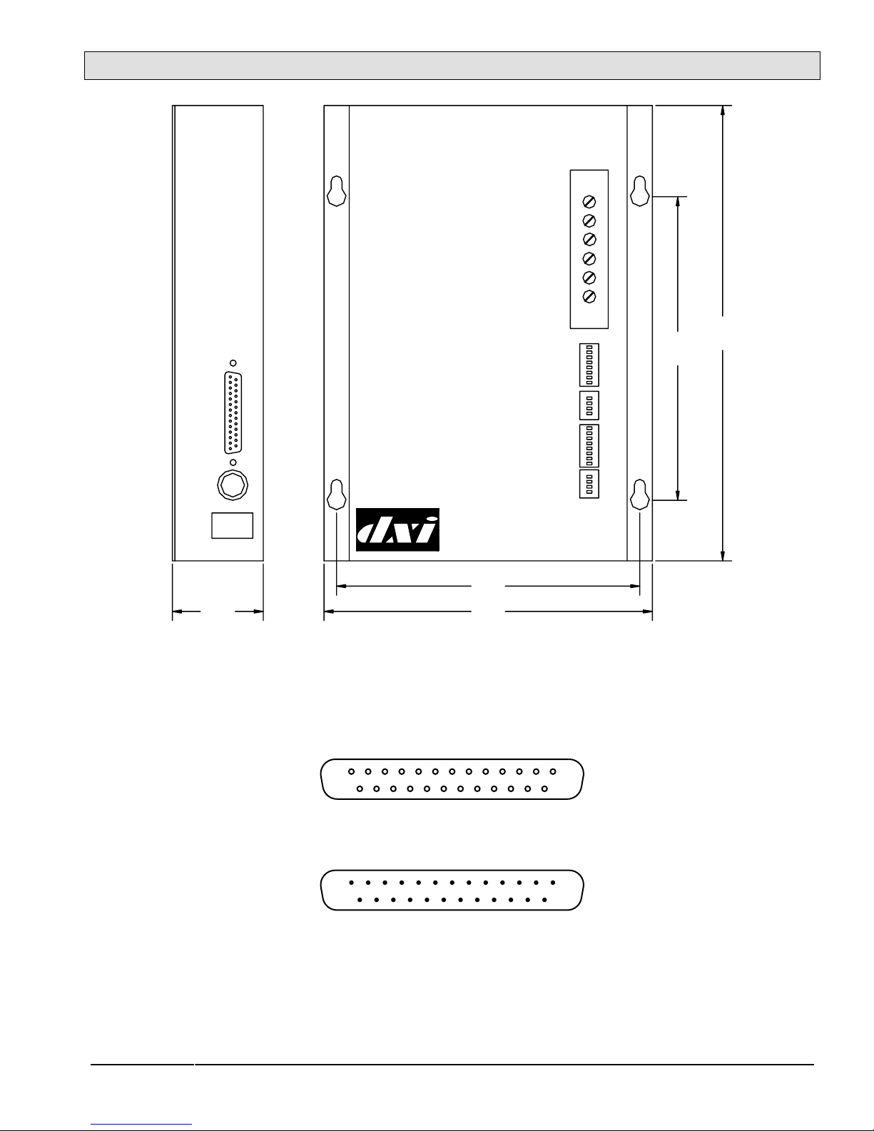
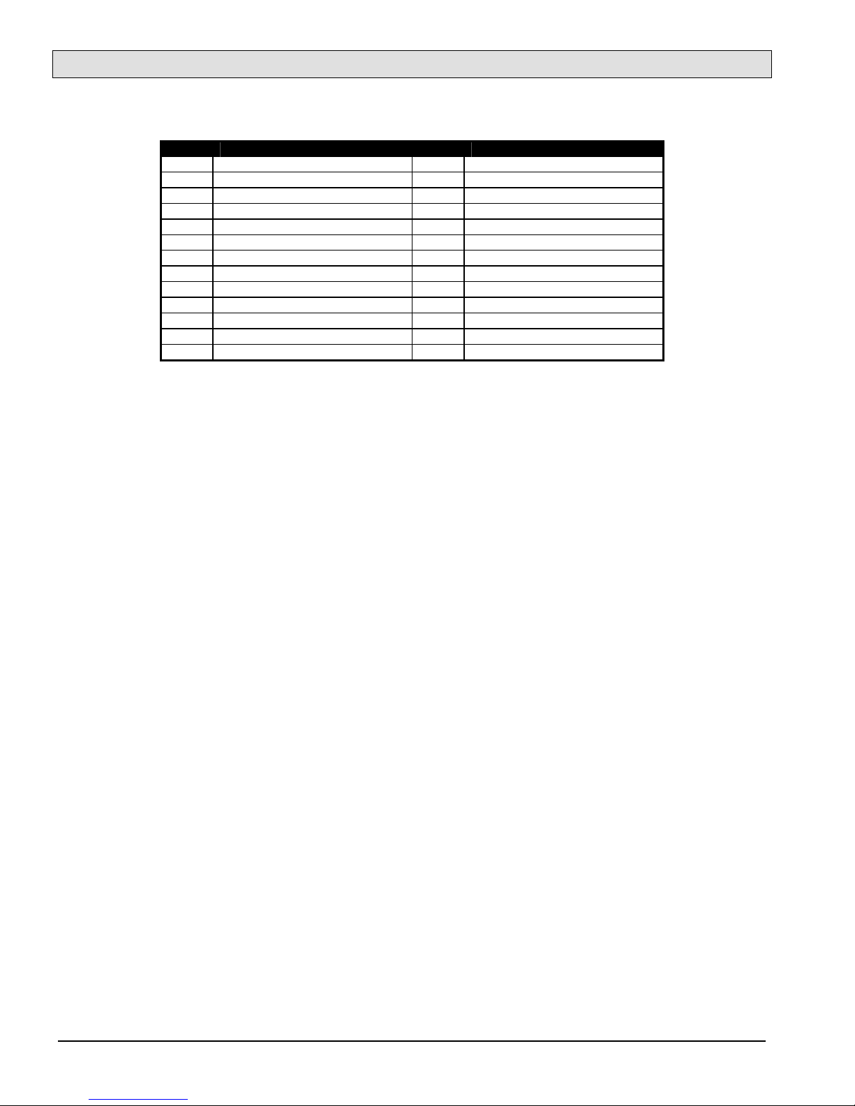
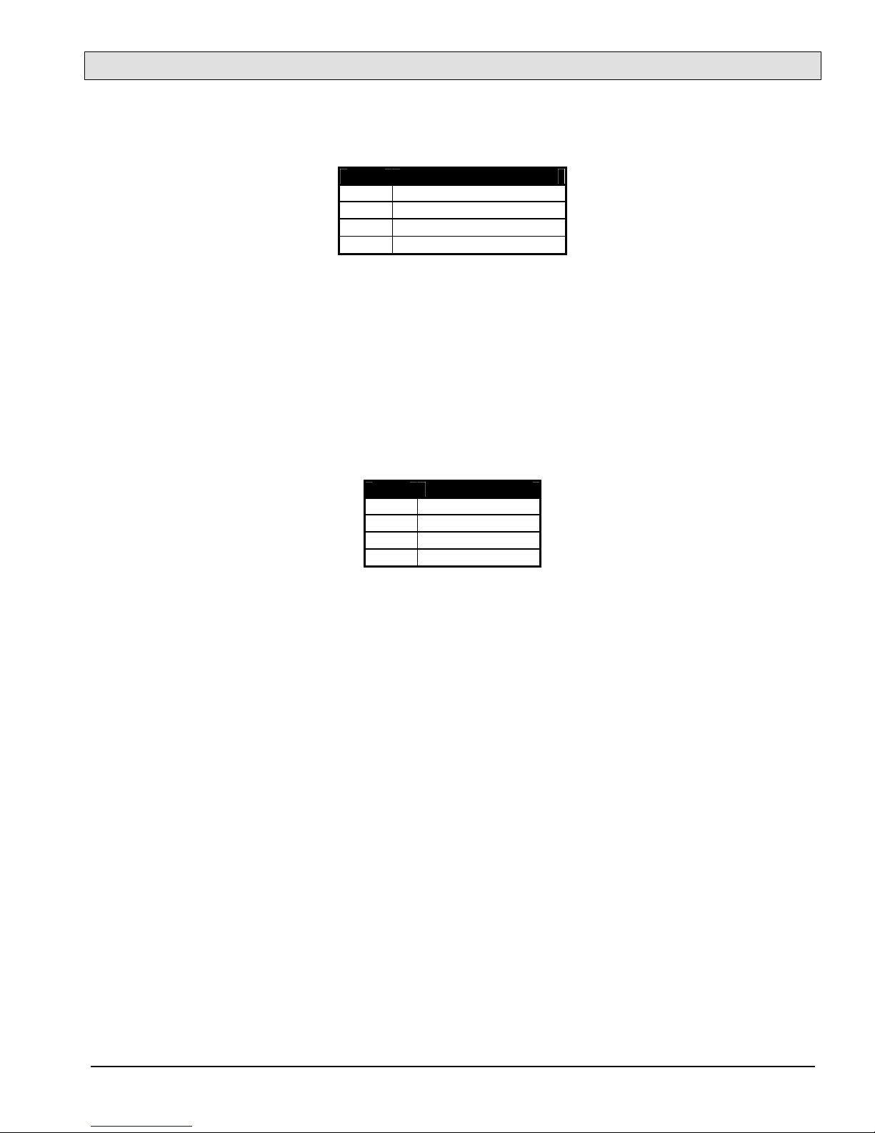
The interface module I/O port requires a female DB-25 mating connector with the following pin configuration:
Pin Signal Pin Signal
1 Main V + 14 Main V +
2 Main V - (Gnd) 15 Main V - (Gnd)
3 NC 16 NC
4 Earth Ground 17 Speaker -
5 Speaker + 18 Microphone -
6 Microphone + 19 Push to Talk Input.
7 NC 20 NC
8 NC 21 NC
9 NC 22 NC
10 Earth Ground 23 NC
11 NC 24 Backup V - (Gnd)
12 Backup V - (Gnd) 25 Backup V +
13 Backup V +
DB-25 Pin Signals
The MAI-125 can be ordered for either +12 Vdc or +24 Vdc operation. For a MAI-125-1 the main power should be
connected to a +12 Vdc power supply, while a MAI-125-2 requires a main power supply of +24 Vdc. For a 12 Vdc
±10% power supply the maximum distance that the power supply can be located from the MAI-125 is 300 feet (90
meters) using a single 22 gauge pair of wires to connect the power supply. For the 24 Vdc ±10% power supply,
and a single 22 gauge pair wire feed, the maximum distance is 750 feet (230 meters). The dc supply can be
connected to pins 1 and 2 as well as pins 14 and 15. This allows the supply wires to be conveniently paralleled to
increase the distance the supply can be located away from the MAI.
The pins labeled Backup V+ and Backup V- (Gnd) can be used to connect a redundant power supply. This supply
acts as a standby power source if the main supply fails. The backup supply must be the same voltage as the main
supply.
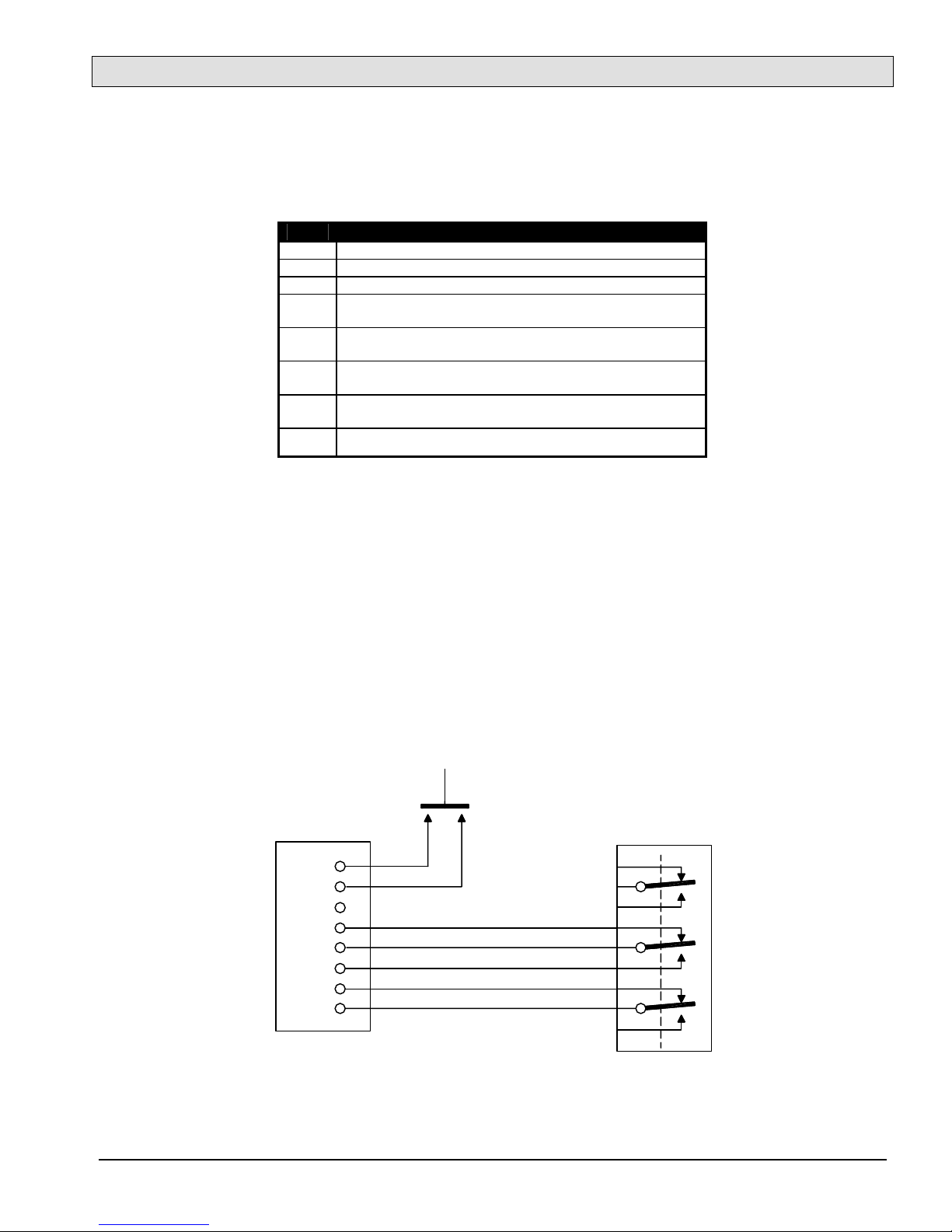
The Speaker and Microphone audio pairs connect to two SAB audio ports through the cross connect blocks. This
connection is made with two shielded pair cables.
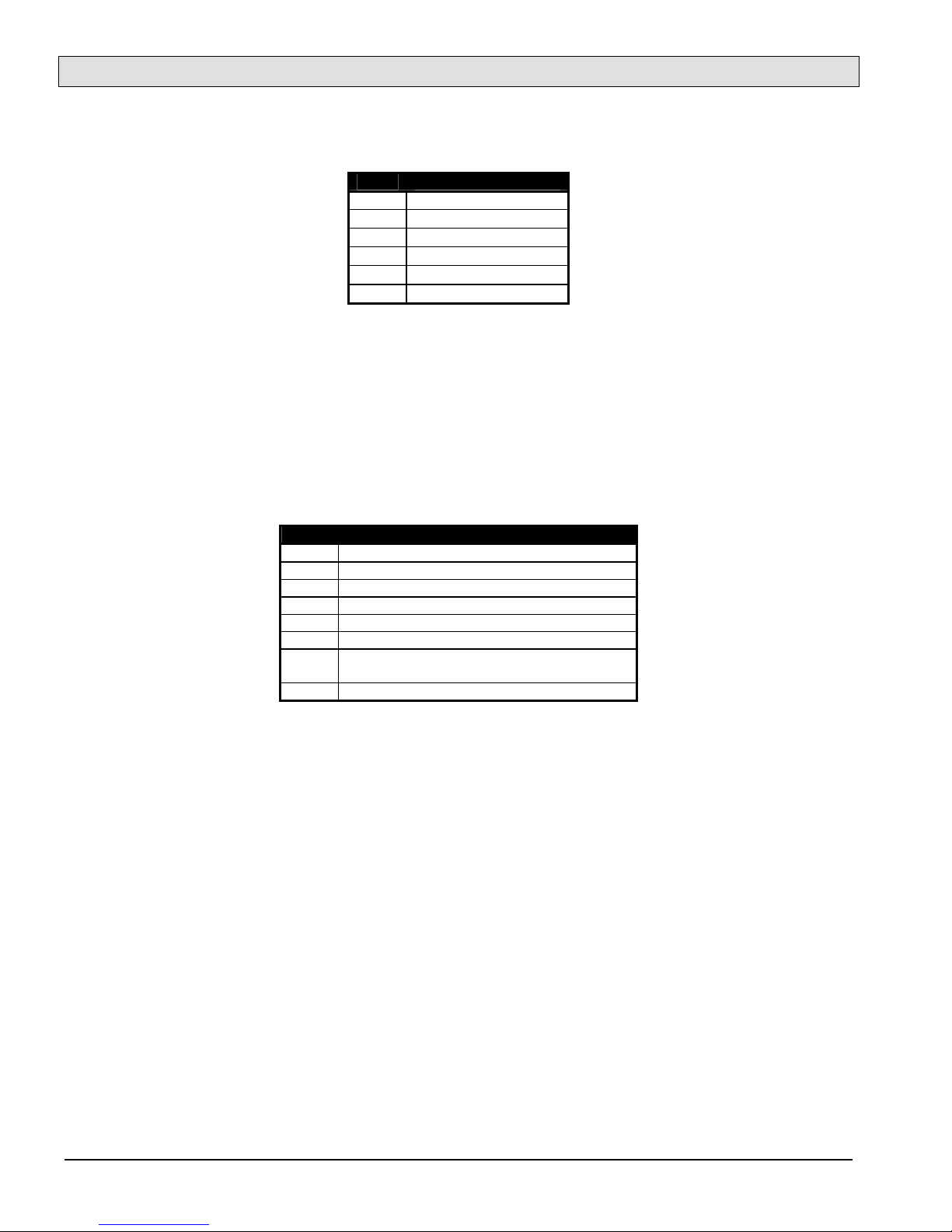
When the MAI-125 is used with the SAB-100 the Speaker pair can be connected to the SAB Audio 16 pair and the
Microphone pair connected to the SAB Master Audio pair. Again the shields are tied together on pin 48. With the
SAB-100 the MAI-125 audio lines can also be connected to two adjacent Audio pairs (2-3, 4-5, 6-7, 8-9, 10-11, 12-
13, or 14-15), with the Speaker pair connected to the even number SAB-100 Audio ports, the Microphone pair
connected to the odd number SAB-100 Audio ports, and the shields connected to the individual shield terminals.
The Push to Talk (PTT) input is referenced to V- (Gnd) (as are the other PTT inputs), i.e. a PTT switch is
connected between the PTT input and V- (Gnd). The Main V- and Backup V- are connected inside the MAI-125.

MAI-125 Master Audio Interface
Document IM-MAI-125-2.2 Page 5
If the telephone hookswitch is used, it is wired to the interface module via an 8-pin MTA-100-08 male connector
as given by the following table. This connector also provides two terminals that can be used to connect an
external switch that allows all microphones to be muted.
Pin Signal
1 Microphone Mute +
2 Microphone Mute - (Gnd)
3 NC
41Hand set Speaker+. Must connect to pin 5 when hand
set is off-hook.
51Speaker+ common. Must connect to pin 4 when hand
set is off-hook, pin 6 when hand set is on hook.
61Headset Speaker+. Must connect to pin 5 when hand set
is on-hook.
7 Speaker/Hand set. Must connect to pin 8 when hand set
is off hook.
8 Gnd
Interface Module Hook Switch Connector
1Note that if a hook switch is not connected to the unit a jumper should be used to connect pins 5 and 6 to allow
normal headset and handsfree switching. If a handset is the only audio device that is going to be used then the
hookswitch is not required. In this case a jumper should be installed between pins 5 and 4. As well a jumper must
be installed between pins 7 and 8 to activate the handset microphone. These jumpers imitate the off hook state of
the hookswitch.
If a hook switch is required the following schematic shows the necessary field wiring. Harding Instruments
provides a Hookswitch Kit HHK-130 that can be used with the MAI-125.
1
2
3
4
5
6
7
8
Hook
Switch
OFF HOOK
ON HOOK
Microphone
Muting Switch
MTA-100-08
Hook Switch Connections

MAI-125 Master Audio Interface
Page 6 Document IM-MAI-125-2.2
The telephone handset is wired to the interface module terminal block according to the following table:
Pin Signal
1 Speaker +
2 Speaker - (Gnd)
3 PTT switch +
4 PTT switch - (Gnd)
5 Microphone +
6 Microphone - (Gnd)
Interface Module Handset Connector
The telephone hand set must have an electret (or condenser) microphone. Connect the speaker (or receiver) wires
to pins 1 and 2, and the Microphone (or transmitter) wires to pins 5 and 6. The PTT switch is connected to pins 4
and 5. Note the speaker connections are not polarity sensitive, however the electret microphone connections are
polarity sensitive and must have the correct polarity connection for proper operation.
The headset with boom microphone connects via an 8-pin MTA-100-08 connector as per the following table:
Pin Signal
1 Speaker +
2 Speaker - (Gnd)
3 PTT switch +
4 PTT switch - (Gnd)
5 Microphone +
6 Microphone - (Gnd)
7 Speaker/Headset - Should connect to pin 8
when headset is plugged in.
8 Gnd
Interface Module Headset Connector
If the headset is always used then a jumper can be used to connect pins 7 and 8. If the headset is used
occasionally then a contact (between pins 7 and 8) is required to activate the headset. This can be an auxiliary
contact on the headset jack, a pair of shorted pins on the headset plug, or a manual switch. Harding Instruments
provides a Headset HEA-110 with a 6-pin plug that can be used with the MAI-125.

MAI-125 Master Audio Interface
Document IM-MAI-125-2.2 Page 7
For handsfree operation speaker and microphone connections are made through a 4-pin MTA-100 connector
according to following table:
Pin Signal
1 Speaker +
2 Speaker -
3 Microphone - (Gnd)
4 Microphone +
Interface Module Speaker/Microphone Connector
Harding Instruments provides a Speaker/Microphone Kit SMK-130 that includes a loudspeaker and microphone
mounted on a baffle plate. It is intended to mount behind a console or panel faceplate. See the IM-SMK-130
Installation Bulletins for further details.
A phantom powered microphone may be connected to the interface module as given by the following table. The
phantom powered microphone must operate on a 12 Vdc supply. Either a panel microphone or a phantom
microphone can be used, but not both at the same master.
Pin Signal
1 Phantom Mic +
2 Phantom Mic -
3 Gnd
4 Gnd
Interface Module Phantom Powered Microphone Connector
Table of contents