Dycon D2366 User manual

Operation Manual
for the D2366
GSM Radio Signal Analyser
This operation guide is for software version 2.
Dycon Ltd
Tel: +44 (0)1443 471 060
Fax: +44 (0)1443 479 374
Cwm Cynon Business Park – Mountain Ash – CF45 4ER - UK
www.dyconsecurity.eu

D2366 GSM Radio Signal Analyser – Operation Manual – D2366-OPS2/EU/F10/v4 - 2
TABLE OF CONTENTS
Product Description 3
GSM Radio Signal Analyser Contents 3
Basic Tests
Using the GSM Radio Signal Analyser 4
Site Survey 6
Fitting a SIM Card 6
Entering a SIM Card’s PIN number 7
Detailed Information
Startup Screen 8
Main Menu 8
Setup Screen 9
Options Screen 10
Survey Screen 11
Results Screen 12
Monitor Screen 14
Screensaver 16
Aerial Siting 16
BER Measurement 17
Battery and Charging 18
Other Information
Appendix 1 – Specification, Approvals and GSM Faults 19
Appendix 2 – Glossary of Terms 20

D2366 GSM Radio Signal Analyser – Operation Manual – D2366-OPS2/EU/F10/v4 - 3
Operation Manual
Description
The D2366 is a radio signal analyser for use with GSM and GPRS radio networks where
automatic signalling equipment is used, including the D2300, D2400 and D2600 ranges of Dycon
products. It may be used to position an aerial and to test the performance of aerial systems.
The GSM radio signal analyser will measure and display radio signal strength received, plus
levels of interference may be measured and sources of interference identified.
The GSM radio signal analyser contains a battery allowing remote operation for up to 12 hours.
The internal battery may be recharged from the supplied mains power supply or a car lighter
socket.
If the GSM radio signal analyser is left switched on and unused, the unit will automatically switch
off after a preset time.
The GSM radio signal analyser is contained within a strong protective sleeve and is supplied
complete with a charger and manual.
Warning – only use with the supplied charger.
Radio Signal Analyser Contents
Mains plug-top charger
D2366 GSM Radio Signal Analyser

D2366 GSM Radio Signal Analyser – Operation Manual – D2366-OPS2/EU/F10/v4 - 4
Using the Radio Signal Analyser
Use the test set to do a site survey – see page 6.
1. Charge the battery before use
Connect the aerial (see page 16).
To switch on the radio signal analyser, press
the On/Off button until the logo is shown.
2. This is followed by the Startup screen (see
page 8).
This screen is shown for about 30 seconds
while the radio module is powering up.
3. If a SIM is fitted that requires a PIN, this
screen gives the option to use the Saved PIN
or enter a new PIN (see page 7).
If not, the Main Menu screen will appear.
Once the Saved PIN is used or a new PIN is
entered, the Main Menu screen will appear next.
4. MAIN Menu
(See page 8 for information).
Press the right button to select the Survey
screen.
5. SURVEY Screen
If Engineer mode is selected in Setup, the
following screen will appear.
If Surveyor mode is selected in Setup, the
following screen will appear.
(See page 11 for information)
Press the right button to start the survey.
The radio signal analyser will measure all
detectable cells.
Keep the aerial upright.
Do not move or touch the aerial.
The survey may take up to 3 minutes to
complete.
Shows number of cells detected
Press the down button to select the
Results screen.

D2366 GSM Radio Signal Analyser – Operation Manual – D2366-OPS2/EU/F10/v4 - 5
Using the Radio Signal Analyser (continued)
6. RESULTS Screen
(See pages 12 and 13 for information)
Signal strength and quality (BER) of each
cell is shown in decreasing signal strength.
If a number, and not the name of the
network, is shown, another network search
should be done (see page 12).
Press the right button to display the next cell
(weaker signal).
Press the left button to display the previous
cell (stronger signal).
Press the down button to return to the
Main menu.
In the main menu, scroll down to display the
Monitor Screen.
7. MONITOR Screen
(See pages 14 and 15 for information)
The display is updated every 6 seconds.
It will normally show the strongest cell.
This display is used to locate an area for the
strongest signal strength.
Use this position when installing the aerial.
(See page 16 for more information)
Press the down button to return to the
Main Menu.
8. Select a new survey etc... as required.
9. To switch off, select Power Off in the Main
menu, or press the On/Off button until the
Shutdown screen is displayed.

D2366 GSM Radio Signal Analyser – Operation Manual – D2366-OPS2/EU/F10/v4 - 6
Site Survey
It is recommended that a site survey is conducted prior to installation of any GSM or GPRS
equipment and associated aerial system to confirm that an adequate radio signal is available at
the site.
It is particularly important that a site survey is conducted when:
a. there may be a weak signal strength at the proposed site;
b. it is known that the aerial will be fitted inside a sheet metal covered building or under
a sheet metal roof;
c. the aerial will be on lower floors of buildings in heavily built-up areas.
The D2366 GSM radio signal analyser is ideal for surveying a proposed site for a suitable radio
signal. Note the point of best signal. Install the aerial at this location.
Use the radio signal analyser to find the point of best signal. This means:
- Maximise the SIG (high signal strength received from a base station);
- Minimise the BER (none or low level of interfering signals).
Full details on optimising signal strength and BER are on pages 16 and 17.
Fitting a SIM card
To access the SIM card holder, simply remove the D2366 GSM radio signal analyser out of the
rubber sleeve from the bottom end. You will find a small yellow button - press on it with a pen
and the SIM card holder will be ejected. Fit the SIM card onto the holder and push the latter back
into the D2366.
When no SIM card is fitted, the unit will display results for all networks detected.
When a SIM card is fitted, the unit will be locked to that operator’s network.

D2366 GSM Radio Signal Analyser – Operation Manual – D2366-OPS2/EU/F10/v4 - 7
Entering the SIM Card’s PIN Number
When a SIM card is used that requires a PIN, the following menu will appear:
Use to use the Saved PIN or to choose the other option.
Press to validate your choice.
The following screen will appear to enter a new PIN:
Enter the SIM card’s PIN number the first time the SIM card is used. Once the D2366 has shut
down, this PIN number will be kept in memory.
In case of an incorrect PIN number, the following screens will be shown:
then
Use any key to get back to the Main Menu screen.
In order to enter the correct PIN number, turn the D2366 GSM radio signal analyser off, then
power it up again. The screen with the “Use saved PIN?” or “Enter PIN” options will appear.
Choose “Enter PIN” and follow the instructions on the next screen.
NOTE: the SIM card will be locked after 3 failed attempts at entering the correct PIN code.

D2366 GSM Radio Signal Analyser – Operation Manual – D2366-OPS2/EU/F10/v4 - 8
Operation – STARTUP Screen
If any errors are detected during power-up, a GSM fault number will be shown (see page 19).
Press any button to go to the Main Menu.
Operation – MAIN Menu
This is the menu from which all functions are selected.
Up (highlight an option).
Then select the required option (see below).
Down (highlight an option).
Then select the required option (see below).
Select the highlighted option:
Survey (see page 11)
Results (see page 12)
Monitor (see page 14)
Setup (see page 9)
Options (see page 10)
Power off = switch off (same as Off button)
Go to Startup screen.
(See page 8)
NOTE: when first switched on, the radio signal analyser will still retain the results from the last
survey. These will be available until a new survey is started.
Or

D2366 GSM Radio Signal Analyser – Operation Manual – D2366-OPS2/EU/F10/v4 - 9
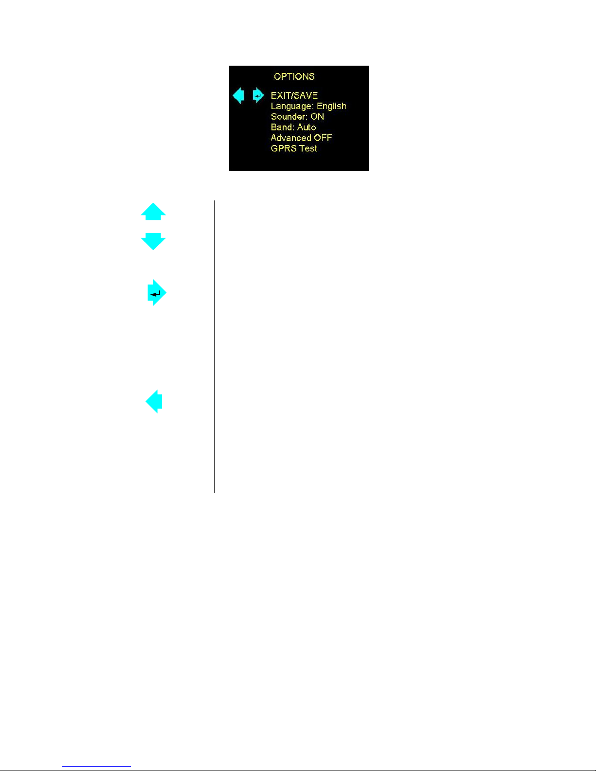
Operation – SETUP Screen
Settings to make the test set operate how you require.
Up (highlight an option)
Then select the option (see below)
Down (highlight an option)
Then select the option (see below).
Right arrow for the selection Option
Exit/Save = save settings then go to Main menu
Contrast = increase display brightness
Delay = increase delay before survey start, from 0 to 99 seconds (1)
Max Cells = increase the number of cells to find during survey (3)
Auto Off = increase minutes to auto-power off
Mode = toggle between Engineer or Surveyor mode
Load Defaults = load factory default settings
Left arrow for the selected Option
Exit/Save = DOES NOT save settings then go to Main menu (2)
Contrast = decrease display brightness
Delay = decrease delay before survey starts, from 99 to 0 seconds (1)
Max Cells = decrease the number of cells to find during survey (3)
Auto Off = decrease minutes to auto-power off
Mode = toggle between Engineer and Surveyor
Load Defaults = no action
(1) This allows positioning of the radio signal analyser in a location and for the surveyor to
retreat before the survey starts.
(2) The selected settings will remain active until the D2366 GSM radio signal analyser is
switched off.
(3) The default is 50 cells. This is the number of cells found, not the number of cells which
are OK. Reducing this number will reduce the time to complete a survey in a high
coverage area. If you are looking for a particular network’s results, reducing this number
may mean you will not see all available cells on your network. To perform a survey on a
particular network, use the facility in the Monitor screen to lock onto a network, then do
the survey.

D2366 GSM Radio Signal Analyser – Operation Manual – D2366-OPS2/EU/F10/v4 - 10
Operation – OPTIONS
Up (highlight an option)
Then select the option (see options below)
Down (highlight an option)
Then select the option (see options below)
Right arrow
Exit/Save = save settings then go to main menu
Language = toggle between available languages
Sounder = select On
Band = select between Auto / EUR / USA
Advanced = select ON (1) (Engineer mode only)
GPRS Test = test the GPRS link (this is a UK-only option and
requires an appropriate SIM card)
Left arrow
Exit/Save = DOES NOT save settings then go to Main Menu
Language = toggle between available languages
Sounder = select OFF
Band = select between Auto / EUR / USA
Advanced = select OFF (1)
GPRS Test = no action
(1) – selecting ON or OFF in Advanced will change the level of information available on the Monitor
screen – the minimum and maximum values shown under the name of the network operator will only
appear on the screen when Advanced = ON is selected.
Remember: in order to select ON or OFF in Advanced, the Engineer mode must be selected first in
Setup. OFF is the default in the Surveyor mode.

D2366 GSM Radio Signal Analyser – Operation Manual – D2366-OPS2/EU/F10/v4 - 11
Operation – SURVEY
This looks for all cells in the area and measures their performance. A survey can take up to 3
minutes.
Surveyor Mode
Go to Main Menu. See previous page.
Go to the Results screen.
First, start the survey. See below.
Shows quantity of cells.
When complete, use this button to get the
results of this survey (see pages 12 and 13).
Start the survey.
Start a network search (Engineer Mode).
(1
)
(1) – The network search is done automatically when a survey is started in Surveyor mode

D2366 GSM Radio Signal Analyser – Operation Manual – D2366-OPS2/EU/F10/v4 - 12
Operation – RESULTS
It displays the performance of all cells measured in the survey.
Swap between Summary (basic) and Detailed
views (only in Engineer mode - see next page).
Go to Main Menu (see page 8).
Display first and subsequent (weaker) cell’s
results (see next page).
Display previous cell’s results (stronger signal)
(see next page).
NOTE: when first switched on, the test set will still retain the results from the last survey. These
will be available until a new survey is started.
Summary (basic) View
INDEX During the survey, each detected cell is given a number. The cell with the
strongest signal is given number 1.
Higher numbers = lower strength signal
GSM 900 or 1800 MHz
The radio frequency band used by the displayed cell
Radio signals using 900MHz penetrate better into buildings.
CELL Cellular identification number of the cell
SIG Signal Strength
Shown as a percentage – 33% and above is useable.
BER Interference
Good = none or low levels
Poor = low to medium levels
Bad = medium or high levels
(see page 17 for more information)
NETWORK The network name of the displayed cell
(1)
SIM Not Fitted or Status
(1) – If the MCC and MNC codes are shown instead of the network name, do another network
search (Engineer mode) or another survey.

D2366 GSM Radio Signal Analyser – Operation Manual – D2366-OPS2/EU/F10/v4 - 13
Operation – RESULTS (cont’d)
Detailed View
This screen is only available in Engineer Mode.
From the Results menu, press the up arrow to get to the Detailed View screen:
INDEX During the survey, each detected cell is given a number.
The cell with the strongest signal is given number 1.
Higher numbers = lower strength signal
ARFCN Absolute Radio Frequency Channel Number
BSIC Base Station Identity Code – identifies the beacon frequency
CELL Cellular identification number of the cell
LAC Local Area Code – identifies the area in which the cell is situated
SIM Not Fitted or Status
dBm FSSI Signal Strength – scale = decibels ref to 1mW
BER Interference – scale 1% = 1 bit corrupted per 100 bits received
MCC Mobile Country Code – a 3-digit number = country (234 = UK)
MNC Mobile Network Code – a 2 or 3-digit number = network within the country
Vodafone UK = 15

D2366 GSM Radio Signal Analyser – Operation Manual – D2366-OPS2/EU/F10/v4 - 14
Operation – MONITOR
It displays the base station with the strongest signal on the selected network. The readings are
updated every 6 seconds.
Swap between Summary (basic) and Detailed
views (only available in Engineer mode - see next
page)
Go to Main menu
(see page 8)
When SIM card is fitted = no action
When SIM car is absent = lock onto selected
network
First highlight the network required (use left
button), then... press the right button to select.
Wait (1 minute maximum).
When SIM card is fitted = no action
When SIM card is absent = highlight Network
Press repeatedly to highlight the required network,
then press the right button to select.
To obtain the list of network operators, select
Network Search by pressing the left arrow, then
press the right arrow.
To return to auto mode after having selected a
particular network operator, select Auto and press
the right arrow.
Summary (basic) View
The displayed cell is the strongest on the selected network. The display is updated every 6
seconds. As the aerial is moved, then a different, stronger cell may be displayed.
GSM 900 or 1800 MHz
The radio frequency band used by the displayed cell
Radio signals using 900MHz penetrate better into buildings
SIG FSSI Signal Strength
Shown as percentage - 33% and higher is useable.
CELL Cellular identification number of the cell
BAT % = charge remaining in battery – 100% = fully charged
EXT = charger connected
SIM Not Fitted or Status
Surveyor Mode Engineer Mode (Advanced ON)

D2366 GSM Radio Signal Analyser – Operation Manual – D2366-OPS2/EU/F10/v4 - 15
Operation – MONITOR (cont’d)
Detailed View
This screen is only available in Engineer Mode.
From the Monitor menu, press the up arrow to get to the Detailed View screen:
Advanced (in Setup) = OFF Advanced (in Setup) = ON
NETWORK The network to which the cell belongs, e.g. Vodafone
GSM 900 or 1800 MHz
The radio frequency band used by the displayed cell
Radio signals using 900MHz penetrate better into buildings
BSIC Base Station Identity Code – identifies the beacon frequency
CELL Cellular identification number of the cell
SIM Not Fitted or Status
dBm FSSI Signal Strength – scale = decibels ref to 1 mW
CSQ FSSI Signal Strength – scale = 0 – 31 (12 and above is acceptable)
BAT % = charge remaining in battery – 100% = fully charged
EXT = charger connected
Min The minimum signal strength measured on this cell, if the cell number
changes this value is reset.
Max The maximum signal strength measured on this cell, if the cell number
changes this value is reset.
BAT % = charge remaining in battery – 100% = fully charged
EXT = charger connected
Jamming Detection
If a jamming signal is detected, <<JAMMING>> will be displayed on the Monitor screen.
Operation – SCREENSAVER

D2366 GSM Radio Signal Analyser – Operation Manual – D2366-OPS2/EU/F10/v4 - 16
It reduces battery usage to a minimum.
Press any button to return to the previous screen.
Aerial Siting
ALWAYS do a site survey to find the point of best signal before installation.
The aerial should be mounted vertically at the point of best signal. This is usually the highest
point in the building (often the loft area). For security applications, the position chosen should be
inside the protected area.
Large metal structures can affect radio signals. Therefore, whenever possible, avoid installing
the aerial directly under sheet metal roofs or within sheet metal covered buildings because this
will reduce the signal strength. If this is unavoidable, the strongest signal will be found away from
the metal roof or close to large external windows or skylights.
Many large buildings closely spaced together will reduce the signal strength, particularly for
aerials on the lower floors, e.g. ground floor installation in city centres. The strongest signal will
normally be found close to external windows or skylights as high as possible.
Wherever possible, do not install the aerial close (2 metres) to sources of interfering signals.
These include: fluorescent or neon lighting, power distribution panels, power cable runs, fridges,
freezers, air-conditioning and ventilation equipment as well as electronic equipment, e.g.
photocopiers, fax machines, computers, televisions...
Reliable radio operation is unlikely with low signal strength, with an incorrectly installed aerial or
with strong interfering signals.
Use the test set to find the point of best signal. This means:
- Maximise the SIG (high signal strength received from a base station);
- Minimise the BER (none or low level of interfering signals).
The supplied short black aerial is for hand-held use, i.e. site surveys.
OR
Use an aerial adapter to connect and test a remote aerial.
Remember: It is always easier to find the point of best signal before the equipment is fitted on
the wall. Moving aerials, cables, trunking... after installation is wasted time and effort.

D2366 GSM Radio Signal Analyser – Operation Manual – D2366-OPS2/EU/F10/v4 - 17
BER (Bit Error Rate)
The BER (Bit Error Rate) is the level of GSM interfering signals received by the GSM radio signal
analyser.
The BER measurement in the Result screen may be used to detect GSM radio signals that are
being corrupted by interfering radio signals.
Sources of interfering signals may be: fluorescent or neon lighting, power distribution panels,
power cable runs, fridges, freezers, air-conditioning and ventilation equipment as well as other
electronic equipment, e.g. photocopiers, fax machines, computers, televisions...
This test may be used with a mobile aerial to detect locations where interfering signal strengths
are stronger or weaker.
When determining a position for an aerial, for best performance, select a location where there are
no effects from interference. See page 16.
In most cases, interfering sources only radiate short distances so that relocating the aerial 2 to 4
metres away from the source will cure interference effects.
When the BER measurement in the Results screen shows Good
The measured BER value indicates none or low levels of interference.
This is the ideal BER reading that can only be achieved by locating the aerial away from sources
of interference.
When the BER measurement in the Results screen shows Poor
The measured BER value indicates low or medium levels of interference.
Where occasional interference corrupts some data, the automatic error correction will repair this
level of interference. Reliable radio operation should not be expected.
When the BER measurement in the Results screen shows Bad
The measured BER value indicates medium or high levels of interference.
Error correction may repair some of the corruption caused by interference but reliable operation
should not be expected in all instances. High levels of interference may completely inhibit
operation. Relocation of the aerial to improve the BER is essential.

D2366 GSM Radio Signal Analyser – Operation Manual – D2366-OPS2/EU/F10/v4 - 18
Battery and Charging
Before first use, fully charge the battery.
When charging, use only the supplied mains plug-top power supply.
A completely flat battery will recharge within 3 hours (typically 2 hours).
A fully charged battery will operate the test set for up to 12 hours.
The battery state may be read on the Monitor screen. See page 14.
When the charger is connected, the unit is always on and the On/Off button will not turn the unit
off.
When the charger is disconnected, the GSM radio signal analyser will automatically switch off
within one minute or after the preset time has expired.
If the GSM radio signal analyzer is left switched on and unused (no buttons are being pressed),
the unit will automatically switch off after a preset time to preserve the battery life. The preset
time may be changed in the Setup screen. See page 9.
The internal battery is a Solid Electrolyte Lithium long type that may be transported, charged and
used in any orientation. It should be protected from frost and temperatures above 40°C.
As with all rechargeable batteries, over several years, its capacity to store power will degrade. If
the operational life of the battery reduces below 1 hour, contact your supplier for replacement
information.
Do not attempt to open the case or remove the battery.

D2366 GSM Radio Signal Analyser – Operation Manual – D2366-OPS2/EU/F10/v4 - 19
APPENDIX 1
Specification
Model D2366 Radio GSM Radio Signal Analyser
Dimension (h x w x d) 135 x 78 x 33mm
Weight 210 grams (including aerial)
Temperature -20°C to +60°C transit / -4C to +40C operating
Humidity 0 – 80% non condensing
Warranty 2 years
Radio Path GPRS and GSM
Battery 3.7 volt, 640mA/h Solid Electrolyte Lithium Ion
Charger Nokia Type ACP-12X or equivalent specifications
Power Consumption Mains 50mA (operation and battery recharging)
International Radio Approval
The D2366 radio GSM radio signal analyser incorporates an independently tested and approved
GSM/GPRS radio module that meets the requirements of European radio communication
standards.
Approval Authority: CE0168
GSM Faults
The list below shows all the faults that may be shown on power up:
Fault number Meaning
1 Timeout waiting for PIN
2 No response from module
3 SIM not fitted (not a fault)
4 PUK required
5 Wrong PIN
6 Not used
7 - 11 Module fault

D2366 GSM Radio Signal Analyser – Operation Manual – D2366-OPS2/EU/F10/v4 - 20
APPENDIX 2
Glossary of Terms
BER – Bit Error Rate
A count or level of interfering signals received by the test set.
CELL – Cellular Identity Number
A number to uniquely identify each GSM/GPRS base station in the UK.
FSSI – Forward Signalling Strength Indication
This is a value indicating the radio signal strength received from the base station at a
GSM communicator or the GSM radio signal analyser.
GPRS – General Packet Radio Service
A packet-based network, within the GSM system, where cost is determined by data
quantity (as distinct from a circuit switched network, where cost is determined by time).
Data rates range from14.4kbps, using just one of the available TDMA time slots, up to a
theoretical 115 kbps when all eight time slots are used. Being a packet-switched system,
the bandwidth within each GPRS cell sector will be divided between all the subscribers.
GSM – Global System for Mobile communication
A second generation cellular telecommunication system, originally for Europe, now global.
A circuit-switched network, where cost is determined by time. It operates in 3 frequency
bands: 900MHz, 1800MHz and 1900MHz.
SIM – Subscriber Identity Module
This is usually referred to as a SIM card. The SIM is the user subscription to the mobile
network. The SIM contains relevant information that enables access onto the subscripted
operator’s network.
Table of contents
Popular Measuring Instrument manuals by other brands

Cirrus Research
Cirrus Research CR308 Instrument handbook

Eversan
Eversan 9658 instruction manual

Bürkert
Bürkert 8025 Series operating instructions

Skil
Skil CROSS-LINE LASER 1910 Original instructions

Milwaukee
Milwaukee REDLITHIUM L4 CLL, REDLITHIUM L4 CPL Operator's manual

ALLIANCE
ALLIANCE POM100 user manual