Dynalloy Muscle Wires FrankenSerial Interface User manual

F2893 1-089 V3.0 ©MMVII Muscle Wires®
and Flexinol® are registered trademarks of Dynalloy
The FrankenSerial Interface extends the input
/ output (I/O) capabilities of the BASIC
Stamp single-board computer, or any
computer capable of communicating via 2400
or 9600 baud serial. The computer reads and
writes the Interface’s 16 I/O pins using the
Serin and Serout commands. The Stamp can
also read the Interface’s eight-bit analog-to-
digital converter (ADC), which can measure
voltages between 0 and 4.7V DC and return a
proportional value of 0 to 255.
Kit requires soldering, basic tools and a PC
with parallel port.
HT Alloy Thermal
Cycle Rate
(cyc/min
9
55
50
Thermal
Activation Start
Temp. (°C)
Activation Finish
Temp. (°C)
Relaxation Start
Temp. (°C)
Relaxation Finish
Temp. (°C)
Annealing Temp.
(°C)
Melting Temp.
(°C)
Specific Heat
(cal/g°C)
Heat Capacity
(Joule/g°C)
Latent Heat
(Joule/g)
LT Alloy
68
78
52
42
300
1,300
0.077
0.32
24.2
HT Alloy
88
98
72
62
300
1,300
0.077
0.32
24.2
Material
Density (g/cc)
Maximum Recovery
Force (MPa)
Recommended
Deformation Force
(MPa)
Breaking Strength
(MPa)
Poisson’s Ratio
Work Output (Joule/g)
Energy Conversion
Efficiency (%)
Maximum Deformation
Ratio (%)
Recommended
Deformation Ratio (%)
6.45
600
35
1,000
0.33
1
5
8
3-5
(~43 ton /
in2)
(~2.5 ton
/ in2)
(~71 ton /
in2)
Phase Related
Phase
Resistivity (µΩcm)
Young’s Modulus
(GPa)
Magnetic
Susceptibility
(µemu/g)
Thermal
Conductivity
(W/cm°C)
Martensite
76
28
2.5
0.08
Austenite
82
75
3.8
0.18
™
1.0 Introduction
FrankenSerialInterfaceKit
Muscle Wires® Moving Electronics Kit
2.0 Parts List
The kit includes the following:
Item Quan Location Description
1. 1 R2 Resistor 470 Ω1/4w 5%, yel vio brn gold
2. 3 R3, R5, R7 Resistor 100K Ω1/4w 5%, brn blk yel gold
3. 2 R4, R6 Resistor 1.0K Ω1/4w 5%, brn blk red gold
4. 1 R8 Resistor 220 Ω1/4w 5%, red red brn gold
5. 2 C1, C2 Capacitor ceramic mono 0.1µF 50v 20% radial Z5U
6. 2 J4, J5 Socket 1 x 10 SIP
7. 1 U1 Socket 8-pin DIP
8. 1 U2 Socket 28-pin DIP
9. 1 J1 Header, Male 0.100” 1 x 3
10. 2 J2, BPS Header, Male 0.100” 1 x 2
11. 2 J3, J6 Header, Male 0.100” 2 x 8
12. 1 CR1 Resonator 4MHz with caps
13. 1 U3 IC MN1381 Low Voltage Detect & Reset
14. 1 U1 IC ADC0831 A/D Converter 8-bit Serial I/O
15. 1 U2 IC PIC16C55-XT/P, Programmed
16. 1 BPS Shorting Block (Jumper) 0.1”
17. 1 - PCB, Stamp Stretcher 1B, Rev -
18. 1 - Instructions, FrankenSerial Interface (these!)
Note: Resistor R1 and diode D1 are not required for operation and not included in this kit. See page 3
"Using and reconfiguring the ADC" for details.
3.0 Other Tools and Materials List
In addition, assembly and operation will require:
1. Soldering iron for electronics
2. Solder for electronics
3. Moist sponge to clean soldering iron tip
4. Side cutter
5. Stamp or other computer with 2400 or 9600 baud communication
6. Power source, 5 Volts DC, 5 mA (Stamp 1, Stamp 2, etc.)
4.0 Assembly
The FrankenSerial Interface is an input/output (I/O) extender for the BASIC Stamp single board
computer. The Stamp reads and writes the Interface’s 16 I/O pins using the Serin an Serout
commands. The Stamp can also read the Interface’s onboard eight-bit analog to digital converter
(ADC). The ADC is capable of measuring voltages between 0 and 4.7 Vdc and returning a
proportional value from 0 to 255. The Interface operates at 2400 or 9600 baud.
5.0 Using the FrankenSerial Interface
Generally, assemble the Printed Circuit Board starting with components having the lowest height
above the board, and work upwards - as per the order given in the parts list. Note both the location of
the part (don't put it in the wrong place), and its orientation. Many parts, like diodes and integrated
circuits, can be damaged or destroyed if powered “the wrong way”.
Configuring and connection the Interface to the BASIC Stamp 1
The Interface communicates with the BASIC Stamp through one
Stamp I/O pin. All of the examples here use in 0, but you may use
any available Stamp 1 pin, 0 through 7. You can power the Interface
from the Stamp’s voltage regulator, since the Interface draws less
than 5 mA. However, if you are driving loads with the Interface
and/or the Stamp, make sure that their total current draw doesn’t
exceed the regulator’s 50-mA capacity. If it does, you will need an
external voltage regulator. Figure 1 shows a typical Stamp-to-
Interface connection, using power supplied by the Stamp’s voltage regulator.
The Interface normally operates at 2400 baud – the maximum speed of the original Stamp
and BS1-IC. If you install a shorting jumper on the posts marked BPS, the Interface will
operate at 9600 baud. The Interface only checks BPS at startup; if you install or remove a
jumper while the Interface is powered up, the change won’t take effect until it is turned off
and back on.
Using the digital I/O pins
The Interface’s 16 I/O pins, numbered 0 through 15, are connected to
header stakes at J3 and J6 on the circuit board as shown in figure 2.
The Interface’s I/O lines are electrically identical to those of the
Stamp. When set to output, a pin can source 20 mA and sink 25 mA,
for a total of up to 40 mA (source) or 50 mA (sink) per port.
Interface pins 0 through 7 comprise the “lower” port; pins 8 through
15 are the “higher” port.
When set to input, the Interface’s pins have very high impedance,
leaking no more than 1µA of current in or out, provided input
voltages aren’t more negative than ground, or more positive than the
+ power supply.
Next to the I/O-in headers are 10-conductor inline sockets J4 and J5.
These sockets are also connected to the I/O pins, but have an

F2893 1-089 V3.0 ©MMVII Muscle Wires®
and Flexinol® are registered trademarks of Dynalloy
additional connection at each end for +5 Vdc (top) an ground (bottom). This lets you conveniently
install resistors between the I/O pins and +5 Vdc or ground using SIP resistor packs. If you want to
exclude one of the I/O pins from the pullup or pulldown connection, you can simply cut the
corresponding pin off the resistor pack.
Using and reconfiguring the ADC
The voltage to be measured with the ADC must be positive and referenced to the Interface’s ground.
Do not connect negative voltages, or positive voltages exceeding the ADC voltage reference voltages by
more than 0.5 volts, to the ADC. The input to the ADC is J2. The input is marked +; the other pin is
ground.
The ADC’s voltage reference is normally wired to its positive power-supply
connection y installing a jumper wire at R1 and leaving D1 empty, giving it a
range of 0 to 4.7 Vdc. (The range is not 0 to 5 Vdc as you might expect because
the ADC gets its power from an Interface I/O pin, which has a small internal
voltage drop.) If you want to reduce the upper limit of the ADC’s range, you may
install a zener diode at D1 and 1K resistor at R1 D1 and R1 are not included with
the kit). A 3.3-volt zener at D1 will give the ADC range of 0 to 3.3 Vdc. When you install the zener,
make sure that its striped end lines up with the stripe on the printed symbol on the board.
The LM336 2.5-volt zener comes in a three-wire, TO-92 package. You can install it as shown in figure
3. The unused terminal is meant to allow fine adjustment of the zener voltage or connection of
temperature-compensation circuitry. For most applications, it’s not needed, since temperature drift over
a range from subfreezing to boiling will cause about a 1-bit change in the ADC output.
Caution: Do not connect the ADC’s reference pin to a voltage higher than its supply voltage (at pin 8).
Doing so will damage the ADC.
Programming the Stamp 1
Your Stamp programs control the Interface by issuing commands to it using Serout (2400 baud,
inverted). The commands are abbreviations of the corresponding Stamp commands. For example, to
change Interface pin 13 to output/low, your program would say:
Serout 0,N2400,(“L”,13)
The commands must be in uppercase. Numbers sent to the Interface may be either constants (as
shown), or variables. Do not precede them with the # character, since this causes the Stamp to convert
them to ASCII text, which the Interface doesn’t understand.
The accompanying table lists Interface commands with PBASIC examples. Note that input commands ,
such as Bit, require two PBASIC instructions. The first instruction is a Serout, to send the command to
the Interface, while the second is a Serin, to receive the data.
Using sleep mode
The Interface’s Sleep mode reduces current draw to less than 1 mA, not counting any loads it may be
driving. The interface awakens periodically to check its serial connection to the Stamp to determine
whether it’s time to wake up. If the serial line is low, as it normally is, the Interface goes back to sleep.
If it is high, the Interface wakes up and waits for the serial input to go low again. When it does, the
Interface returns to normal operation.
How often the Interface checks for the wake-up signal depends on the value sent with the Sleep (S)
command as follows:
Interface Sleep Durations
S0 18ms S4 288 ms
S1 36 ms S5 576 ms
S2 72 ms S6 1152 ms
S3 144ms S7 2304 ms
Every time the Interface checks for the wake-up signal, any pins that are configured as outputs will float
for approximately 18 ms. The internal reset mechanism that periodically wakes the Interface to allow it
to check the serial line also briefly forces al pins to input mode, causing them to float. Make sure that
any loads driven while the Interface is asleep can tolerate this glitching. (The Stamp does the same
thing during its Sleep, Nap, and End modes, by the way.)
To wake up the Interface, the Stamp should output a high on the serial communication line for at least
twice (preferable three times) the length of the Interface’s sleep interval. For best ADC accuracy, don’t
request an analog reading for at least 50 ms after waking up the Interface.
Programming Tips
•Reprogramming the Stamp (ALT-R) does not reset the Interface. During program
development, you may want to start your program with several reset commands (*) to put the
Interface into the same state it is in when power is first applied. An alternative is to
disconnect power from the Interface to cause it to forget previous states before
reprogramming. If reprogramming the Stamp interrupts it while it’s sending data, the
Interface may receive the interrupted command incorrectly. Again, the solution is to get the
Interface into a known state by cycling its power.
•At 2400 baud, it takes about 4.2 ms to send a byte of data. This limits the maximum rate at
which you can write data to or get data from the Interface’s I/O pins. For example, the
Toggle instruction takes two bytes so the fastest you can toggle an Interface bit is every 8.4
ms, or approximately 129 times a second (ignoring the Stamp’s program-execution time).
Try to divide up I/O responsibilities so that the fast jobs go to the Stamp’s pins and the slow
jobs to the Interface. (A9600 baud, the situation is better, but the Stamp’s own I/O’s are still
faster.)
•Take advantage of automatic data-direction settings. Just like the Stamp, the Interface wakes
up with all of its pins configured as inputs. The commands High, Low, and Toggle all set the
specified pin to output and leave it in that state. The Read and Write commands do not
change the data directions of the pins. Values written to pins that are configured as inputs
are stored in internal registers of the PIC controller. They don’t affect the state of the pins
until the pins’ data direction is set to output. Likewise, pins that are configured as outputs
can be read, but you will be reading the state most recently written to them.

F2893 1-089 V3.0 ©MMVII Muscle Wires®
and Flexinol® are registered trademarks of Dynalloy

F2893 1-089 V3.0 ©MMVII Muscle Wires®
and Flexinol® are registered trademarks of Dynalloy
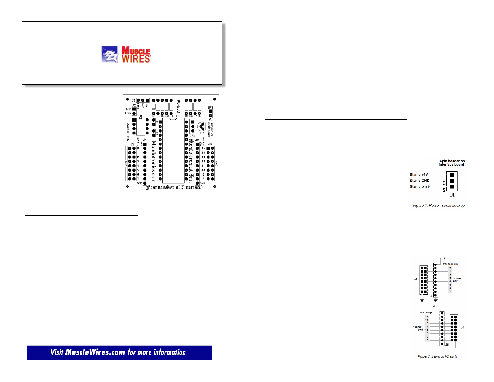
6.0 FrankenSerial Interface Input/Output Commands
FrankenSerial
Command Syntax Action, Stamp Syntax Example
High H [0-15] Turns the selected pin to an output and writes a 1 to it.
SEROUT 0, N2400,(“H”,9) ‘ Sets Interface pin 9
Low L [0-15] Turns the selected pin to an output and writes a 0 to it.
SEROUT 0, N2400,(“L”,b2) ‘ Clears Interface pin
‘ whose number is contained in b2.
Toggle T [0-15] Turns the selected pin to an output and toggles (inverts) it.
SEROUT 0, N2400,(“T”,9) ‘ Toggles Interface pin 9.
Bit B [0-15] Returns the state (0 or1) of the specified bit. Does not affect
the pins’ data direction settings (input or output).
SEROUT 0, N2400,(“B”,15) ‘ Request status of bit 15.
SERIN 0, N2400, b2 ‘ Get bit status in b2.
Analog A Returns a reading (0 to 255) from the ADC.
SEROUT 0, N2400,(“A”) ‘ Request ADC reading.
SERIN 0, N2400, b2 ‘ Get ADC data in b2.
Input I [0-15] Makes the specified pin number an input.
SEROUT 0, N2400,(“I”,b2) ‘ Makes the pin whose number
‘ is stored in b2, an input.
Output O [0-15] Makes the specifies pin number an output. Whatever state was
Last written to the pin (high or low) will be output when this occurs.
If the pin must be in a particular state, use High or Low to make it
an output.
SEROUT 0, N2400,(“O”,3) ‘ Makes pin 3 an output.
Direction, DB Writes the data direction registers of both of the Interface’s I/O
Both ports. A binary 1 in the data-direction register makes the
corresponding pin an output; a 0 makes it an input. The Interface
expects the lower port’s data direction first.
SEROUT 0, N2400,(“DB”,%00001111,%11111111)
‘ Make pins 0-3 outputs, 4-7 inputs. Make all of the
‘ upper port pins outputs.
Direction DL Writes the data direction register of the Interface’s lower I/O port as
Lower in DB above.
SEROUT 0, N2400,(“DL”,255)
‘ Make all of lower port outputs (255 = %11111111).
Direction DH Writes the data direction register of the Interface’s higher I/O port
Higher as in DB above.
SEROUT 0, N2400,(“DH”,255)
‘ Make all of higher port outputs (255 = %11111111).
Read Both RB Reads both of the Interfaces I/O ports. Does not affect
the pins’ data direction settings (input or output). Interface returns
data as two bytes, lower byte first.
SEROUT 0, N2400,(“RB”) ‘ Request read of port.
SERIN 0, N2400, b2,b3 ‘ Get Interface data.
Read Lower RL Reads the Interface’s lower I/O port (pins 0-7) as in RB above.
SEROUT 0, N2400,(“RL”) ‘ Request read of port.
SERIN 0, N2400, b2 ‘ Get Interface data.
Read Higher RH Reads the Interface’s higher I/O port (pins 8-15) as in RB above.
SEROUT 0, N2400,(“RH”) ‘ Request read of port.
SERIN 0, N2400, b2 ‘ Get Interface data.
FrankenSerial
Command Syntax Action, Stamp Syntax Example
Write Both WB Writes both of the Interface’s I/O ports. Does not affect the pins’
data direction settings (input or output). If a pin is set to input at the
time of a write, it will not be affected until I is made an output.
SEROUT 0, N2400,(“WB”, b2, b3) ‘ Write contents of
‘ variable b2 to lower port, b3 to higher.
Write Lower WL Writes the interface’s lower I/O port (pins 0-7) as in WB above.
SEROUT 0, N2400,(“WL”, 255) ‘ Write 1s to all pins
‘ of the lower port.
Write Higher WH Writes the interface’s higher I/O port (pins 8-15) as in WB above.
SEROUT 0, N2400,(“WH”, 255) ‘ Write 1s to all pins
‘ of the higher port.
Sleep S Puts the Interface to sleep. At intervals of 18 ms to 2.3 seconds,
the Interface will check its serial line for a high, signaling it to wake
up.
SEROUT 0, N2400,(“S”, 0) ‘ Sleep. Look for
‘ wakeup every 18 ms.
Reset * Returns the Interface’s I/O pins to their power-up configuration;
All inputs, and all internal latches cleared to 0s. Useful during
Programming to set the interface to a know state. However, if the
Stamp is interrupted in the middle of a multipart command, it may
take as may as three resets to finish the interrupted command and
actually reset the interface.
SEROUT 0, N2400,(“*”) ‘ Reset all pins/directions.
Converting the program examples for use with the BASIC Stamp 2
The BASIC Stamp 2 (BS2) has Serin and Serout instructions that are similar to those of the BS1, but offer
more options. First of all, you can send and receive data at arbitrary data rates up to 50,000 bps, so it’s up to
you to calculate the bit time and other communication parameters, called “baudmodes” in PBASIC. Here are
the baudmodes that apply to communication with the FrankenSerial Interface.
$418d ‘Inverted, 2400 baud.
$4054 ‘Inverted, 9600 baud.
We won’t duplicate the entire instruction table here, just a couple of examples. Suppose you wanted to toggle
pin 10 of the Interface, and that the Interface’s serial pin is connected to BS2 pin 0. Assuming the Interface is
set for 9600 bps (jumper installed on the posts marked BPS), the instruction would be:
serout 0,$4054,[“T”,10] ‘Toggle pin 10.
The same pattern applies to all of the other output-only instructions.
To issue an instruction that expects a serial response (B for bit and A for Analog), you perform Serout to send
the instruction followed by Serin to get the response. For instance, to read the state of Interface bit 15,
assuming BS2 pin 0 for serial communication, 2400 baud (no jumper at BPS), and the existence of a byte
variable named “result,” your instructions would be:
serout 0,$418d,[“B”,15] ‘Request state of bit 15.
Serin 0, $418d, [result] ‘get the response
The BS2 flavors of Serin and Serout have many other options. See the Parallax documentation for details.

F2893 1-089 V3.0 ©MMVII Muscle Wires®
and Flexinol® are registered trademarks of Dynalloy
Contact Us:
Mondo-Tronics products are produced and distributed by:
Dynalloy, Inc. Phone: (714) 436-1206
14762 Bentley Circle Fax: (714) 436-0511
Tustin, CA E-mail: flexinol@dynalloy.com
92780 Website: MuscleWires.com
For sales, new products and support go to www.reachinginsight.com.
Comments? Errors? Improvements? Compliments?
Help us make this product better with your feedback. We want to hear from
you!