VWR avantor INCU-Line Premium Series User manual

Instruction manual
VWR®INCU-Line Premium
Cooled Incubators
European Catalogue Numbers:
INCU-Line 240CR PREMIUM: 390-1335
INCU-Line 150R PREMIUM: 390-1338
INCU-Line 400CR PREMIUM: 390-1336
INCU-Line 250R PREMIUM: 390-1339
INCU-Line 750CR PREMIUM: 390-1337
Version 4.3 Issue 10/2021

Instruction Manual INCU-Line Premium
Page 2/ 61
Legal address of Manufacturer
Europe
VWR International bv
Researchpark Haasrode 2020
Geldenaaksebaan 464 B-3001 Leuven
+3216385011
be.vwr.com
UK Importer
VWR International Ltd
Hunter Boulevard, Magna Park
Lutterworth, Leicestershire, LE17 4XN
uk.vwr.com
Country of Origin
POLAND
Equipment disposal
This equipment is marked with the crossed out wheeled bin symbol to indicate that this equipment must not
be disposed of with unsorted waste.
Instead it's your responsibility to correctly dispose of your equipment at lifecycle -end by handling it over to
an authorized facility for separate collection and recycling. It's also your responsibility to decontaminate the
equipment in case of biological, chemical and/or radiological contamination, so as to protect from health
hazards the persons involved in the disposal and recycling of the equipment.
For more information about where you can drop off your waste of equipment, please contact your local deal-
er from whom you originally purchased this equipment.
By doing so, you will help to conserve natural and environmental resources and you will ensure that your
equipment is recycled in a manner that protects human health.
Thank you!

Instruction Manual INCU-Line Premium
Page 3/ 61
Contents
1. IMPORTANT INFORMATION FOR THE USER................................................................................................5
2. PACKAGE CONTENTS.....................................................................................................................................5
3. BEFORE THE FIRST USE.................................................................................................................................6
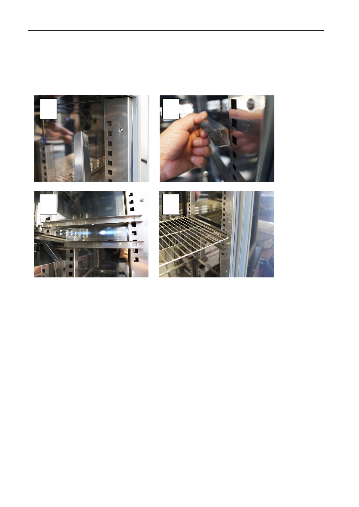
3.1. Shelf installation ..........................................................................................................................................................8
3.1.1. For IL 150R Premium and IL 250R Premium.......................................................................................................8
3.1.2. For IL 240CR Premium, IL 400CR Premium and IL 750CR Premium.................................................................9
3.2. Condensation in the chamber......................................................................................................................................9
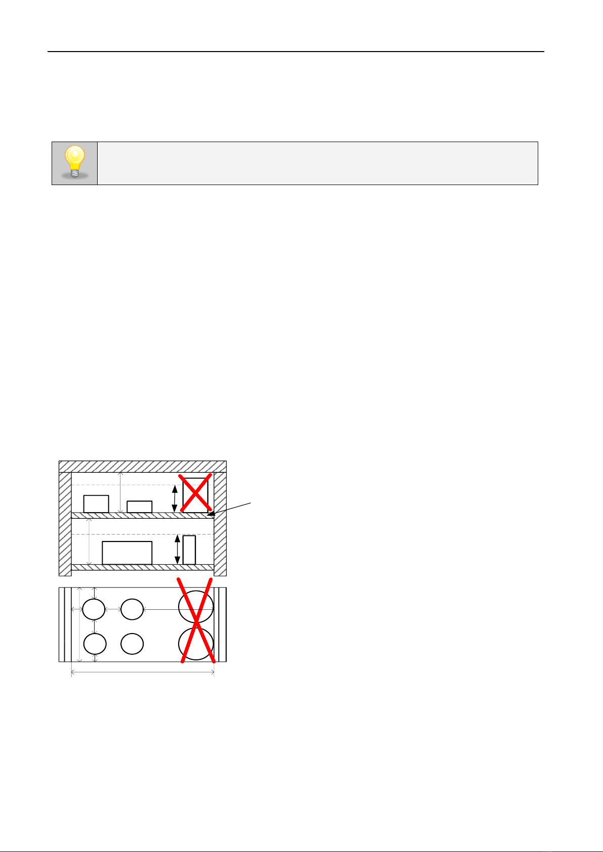
3.3. Placement of samples...............................................................................................................................................10
3.4. Closing the chamber door .........................................................................................................................................11
3.5. Internal glass door.....................................................................................................................................................11
4. OVERVIEW ......................................................................................................................................................12
4.1. IL 150R Premium and IL 250R Premium...................................................................................................................12
4.2. IL 240CR Premium, IL 400CR Premium and IL 750CR Premium .............................................................................13
5. UNIT OPERATION...........................................................................................................................................14
5.1. Internal memory..........................................................................................................................................................14
5.2. First boot.....................................................................................................................................................................14
5.3. Using the keypad........................................................................................................................................................14
5.4. User logging in............................................................................................................................................................15
5.5. Main Screen......................................................................................................................................................16
5.5.1. Alarm bar............................................................................................................................................................17
5.5.2. Alarms panel.......................................................................................................................................................17
5.5.3. Information panel................................................................................................................................................18
5.5.4. Status - description.............................................................................................................................................19
5.5.5. Status –protection and alarms...........................................................................................................................19
5.6. Programs ..........................................................................................................................................................20
5.6.1. Program creating / edition...................................................................................................................................21
5.6.2. Segments edition................................................................................................................................................22
5.6.3. Summary of segments........................................................................................................................................24
5.6.4. Loop....................................................................................................................................................................24
5.6.5. Priority ................................................................................................................................................................25
5.6.6. Protection class ..................................................................................................................................................25
5.7. Starting the program...................................................................................................................................................26
5.8. Quick change of parameters.......................................................................................................................................28
5.8.1. Quick change the set temperature......................................................................................................................28
5.8.2. Quick change the set time ..................................................................................................................................28
5.8.3. Quick change of other parameters.......................................................................................................................29
5.9. Statistics.............................................................................................................................................................30
5.10. Data record......................................................................................................................................................31
5.10.1. Graph.................................................................................................................................................................32

Instruction Manual INCU-Line Premium
Page 4/ 61
5.11. Event log .........................................................................................................................................................33
5.12. Info..................................................................................................................................................................35
5.13. Users...............................................................................................................................................................36
5.13.1. User creating / edition.......................................................................................................................................36
5.14. Types of accounts and their limits .............................................................................................................................37
5.15. Interface..........................................................................................................................................................39
5.16. Time ................................................................................................................................................................40
5.17. Alarms.............................................................................................................................................................41
5.18. Network...........................................................................................................................................................42
5.19. Mail reports .....................................................................................................................................................43
5.20. Defrosting ........................................................................................................................................................46
5.20.1. Defrosting program (only for IL 150 and IL 250 Premium)................................................................................46
5.20.2. Defrosting function (only for IL CR Premium) ...................................................................................................46
5.21. Corrections ......................................................................................................................................................47
6. COMPONENTS OF THE UNIT ........................................................................................................................49
6.1. Internal socket...........................................................................................................................................................49
6.2. Door lock ...................................................................................................................................................................49
6.3. Access port................................................................................................................................................................49
6.4. Open door alarm........................................................................................................................................................50
6.5. Internal light / internal LED light.................................................................................................................................50
6.6. USB port....................................................................................................................................................................51
7. TEMPERATURE PROTECTION.....................................................................................................................52
8. REMOTE CONTROL OF THE UNIT...............................................................................................................52
9. OPERATION OF THE COOLING SYSTEM ...................................................................................................53
10. CLEANING AND MAINTENANCE OF THE UNIT........................................................................................54
10.1. Exterior cleaning......................................................................................................................................................54
10.2. Interior cleaning.......................................................................................................................................................55
11. ADVICE ON HOW TO SAFELY STORE THE DEVICE ...............................................................................55
12. TROUBLESHOOTING..................................................................................................................................56
12.1. Possible defects ......................................................................................................................................................56
13. WARRANTY CONDITIONS..........................................................................................................................57
14. PRODUCT IDENTIFICATION LABEL..........................................................................................................58
15. TECHNICAL DATA.......................................................................................................................................59

Instruction Manual INCU-Line Premium
Page 5/ 61
1. IMPORTANT INFORMATION FOR THE USER
To guarantee your security and the longevity of the unit, please comply with the following rules:
1.
The unit cannot be installed:
outside,
in damp places or places which can be easily flooded,
near flammable or volatile substances,
near acids or in corrosive environments.
2.
It is forbidden to:
store inflammable or volatile substances inside the unit,
touch live parts of the unit,
operate the unit with wet hands,
put water vessels on the unit,
climb or put any objects on the unit,
overload the shelves (the maximum load is described in technical data).
3.
You should:
place samples in such a way to provide proper air circulation in the chamber,
open the door for the shortest period of time to reduce temperature fluctuations,
defrost the chamber if you open the door or store humid samples,
if possible, do not store warm samples,
secure samples from being blown out by the chamber fan e.g. powdery samples,
always check that the doors are closed,
use only earthed mains to avoid electric shocks,
unplug the power cable holding the protective cover and not the cable itself,
disconnect the unit from the mains before undertaking any repairs or maintenance works,
protect the power cable and the plug from any damage,
disconnect the power plug before moving the unit,
disconnect the power plug if the device will not be used for a long period of time,
disconnect the unit if it has any visual faults.
2. PACKAGE CONTENTS
INCU-Line devices are delivered with the following equipment:
INCU-Line 150R Premium, 2 stainless steel wire shelves with set of slides –2 pcs each, 1 bottom stainless
steel wire shelf with set of slides (2 pcs), keys to the lock (2 pcs), Manufacturer test certificate at 37oC,
Ethernet cable. Multilingual instruction manual and Premium Control Software can be downloaded from in-
ternal memory on USB Stick.

Instruction Manual INCU-Line Premium
Page 6/ 61
INCU-Line 250R Premium, 3 stainless steel wire shelves with set of slides –2 pcs each, 1 bottom stainless
steel wire shelf with set of slides (2 pcs), keys to the lock (2 pcs), , Manufacturer test certificate at 37oC,
Ethernet cable. Multilingual instruction manual and Premium Control Software can be downloaded from in-
ternal memory on the USB Stick.
INCU-Line 240CR Premium, 3 stainless steel wire shelves with set of slides –2 pcs each, keys to the lock
(2 pcs), Manufacturer test certificate at 37oC, Ethernet cable. Multilingual instruction manual and Premium
Control Software can be downloaded from internal memory on the USB Stick.
INCU-Line 400CR Premium, 3 stainless steel wire shelves with set of slides –2 pcs each, keys to the lock
(2 pcs), Manufacturer test certificate at 37oC, Ethernet cable. Multilingual instruction manual and Premium
Control Software can be downloaded from internal memory on the USB Stick.
INCU-Line 750CR Premium, 3 stainless steel reinforced wire shelves with set of slides –2 pcs each, keys
to the lock (2 pcs), Manufacturer test certificate at 37oC, Ethernet cable. Multilingual instruction manual and
Premium Control Software can be downloaded from internal memory on the USB Stick.
Description
Quantity
Cat. No.
Additional stainless steel shelf for IL 150 and IL 250 Premium
1
390-1340
Additional stainless steel shelf for IL 240CR Premium
1
390-0967
Additional stainless steel shelf for IL 400CR Premium
1
390-0968
Reinforced stainless steel shelf for IL 240CR Premium
1
390-1035
Reinforced stainless steel shelf for IL 400CR Premium
1
390-1036
Reinforced stainless steel shelf for IL 750CR Premium
1
390-1037
3. BEFORE THE FIRST USE
The surface components of the unit are made of stainless steel, therefore slight discoloration may occur. It is
a result of the technologies used in the production of metal sheet in accordance with the requirements of PN-
EN 10088-2 standard and it is not a defect of the unit.
While carrying the unit, please do not tilt it to one side more than 45° from the upright posi-
tion, as there is a high probability of damaging the compressor. If it is necessary to tilt it to
one side more than 45°, then after siting, please wait at least 3 hours before connecting the
unit to the mains.

Instruction Manual INCU-Line Premium
Page 7/ 61
The place of location of the unit should meet the following conditions:
Ambient temperature between +10°C...+28°C
Ambient relative humidity of 60%
Low dust environment
Appropriately ventilated according to its size
Placed on a hard and stable surface
Placed at least 100 mm away from the wall
Height of the room must be at least 300 mm greater than the height of the unit
Keep away from direct sunlight
Kept away from any heat sources
Not designed to be built-in e.g. within a wall cavity
Placed near a mains socket 230V/50Hz.
Non-compliance with the above recommendations may result in damage to the unit or impair tech-
nical parameters.
The electric installation should meet the following conditions:
The electric installation should be secured by a 16 A antisurge fuse.
The IL 240CR, IL 400CR and IL 750CR units are
equipped with leveling castors. After the unit has been
placed in its destination, lock the castors and level the
unit using the red screw located inside the castor’s cas-
ing. You can adjust the level using fingers or a flat wrench
size 13.
Do not use the castors for transporting the unit! The castors should be used only to move device
in the lab.
The device is powered by AC 220-240V/50Hz. You must be connected to an earthed
mains socket to avoid electric shock in case of potential malfunction.

Instruction Manual INCU-Line Premium
Page 8/ 61
3.1. Shelf installation
3.1.1. For IL 150R Premium and IL 250R Premium
Perform the following steps to adjust shelf height in IL 150R Premium and IL 250R Premium:
1. Install the shelf bracket at the selected height by inserting it into appropriate slots on the chamber
wall.
2. Install the second shelf bracket on the opposite chamber wall.
3. Slide the shelf into the shelf brackets.
4. The shelf is now correctly installed!
1
2
3
4

Instruction Manual INCU-Line Premium
Page 9/ 61
3.1.2. For IL 240CR Premium, IL 400CR Premium and IL 750CR Premium
Perform the following steps to adjust shelf height in IL 240CR Premium, IL 400CR Premium and IL 750CR
Premium:
1. Install the shelf bracket at the selected height by inserting it into appropriate slots on the chamber
wall.
2. Install the second shelf bracket on the opposite chamber wall.
3. Slide the shelf into the shelf brackets.
4. The shelf is now correctly installed!
To remove a shelf, perform the above steps in reverse order. To remove the shelf holder from the slots, lift it
up and slide it towards the rear of the chamber.
3.2. Condensation in the chamber
Water may gather on the bottom of the chamber, as a result of condensation from water vapor if set tem-
perature is considerably lower than the ambient temperature.
1
3
4
2
1

Instruction Manual INCU-Line Premium
Page 10 / 61
The amount of water depends on the following factors:
- Differences between ambient and set temperatures
- Frequency of door openings
- Temperature of samples
Do not use any cardboard boxes, sponges and other hygroscopic materials for storing the samples since
they may increase the relative humidity in the chamber.
3.3. Placement of samples
To provide proper air circulation and stable conditions within the chamber, it is necessary to adhere to the
following rules:
- the max height of the samples should not exceed 2/3 of the shelf space
- the samples should be placed so that the space between the containers does not exceed 1/3 of the
width and height of the shelf
- samples should be placed with equal spacing between each other and the chamber walls
The picture below is an example of the placement of samples in the chamber.
Hmax
H
Hmax
a
uv w
xy z
b
u+v+w > 1/3 a
x+y+z > 1/3 b
Hmax = 2/3H
u v w
x y z
H
≅
≅ ≅
≅
Front view
Top view
Shelf
Following the above rules will provide optimal parameters of temperature variation and fluctuation.
If water gathers, use a dry cloth to wipe the bottom of the chamber.

Instruction Manual INCU-Line Premium
Page 11 / 61
3.4. Closing the chamber door
The external door of the IL 150R and IL 250R incubators has been equipped with a magnetic gasket and
open door sensor. If the door has not been closed properly, an alarm will sound.
The IL 240CR, IL 400CR and IL 750CR incubators have been equipped with a 2-point lock. To close the
door, turn the handle to the vertical position, push the door gently then turn the handle to the horizontal posi-
tion. If the door has not been closed properly, an alarm will sound. Closing the door correctly reduces energy
consumption and ensures consistent temperature variation and fluctuation.
3.5. Internal glass door
To open or close the internal glass door use the plastic handle installed on the glass. While operating the
unit at high temperatures, do not touch the glass door or inner parts of the chamber. Always use safety
gloves to protect yourself and minimise the risk of getting burnt.

Instruction Manual INCU-Line Premium
Page 12 / 61
(1) Electronic controller with 7” touch panel
(2) USB port
(3) Chamber fan
(4) Access port (30 mm)
(5) Shelf
(6) Height adjustable feet
(7) Key lock
(8) Internal electrical socket
(9) Internal LED lighting
(10) Temperature sensor
(11) Main power socket
(12) LAN
(13) Main power switch
(14) Condenser
(15) Compressor
4. OVERVIEW
4.1. IL 150R Premium and IL 250R Premium
1
3
4
5
10
6
8
9
2
7
14
15
11
13
12

Instruction Manual INCU-Line Premium
Page 13 / 61
(1) Electronic controller with 7” touch panel
(2) Access port (30 mm)
(3) Chamber fan
(4) Shelf
(5) USB port
(6) Internal lighting
(7) Temperature sensor
(8) Castors
(9) Main power switch
(10) Main power socket
(11) Fan cover
(12) Cooling system
(13) LAN
4.2. IL 240CR Premium, IL 400CR Premium and IL 750CR Premium
8
1
2
3
4
5
7
6
13

Instruction Manual INCU-Line Premium
Page 14 / 61
5. UNIT OPERATION
This symbol means that a given field / window can be moved in the direction shown in
the picture.
5.1. Internal memory
It may be necessary to use the data from the external memory –a USB stick. The USB stick should be for-
matted the FAT 32 file system. The USB stick should be placed in USB slot located on the front the device,
near to the display. Wait a few seconds, the correct reading is indicated by the message „USB flashdrive
connected” at the bottom of the screen.
5.2. First boot
During the first boot, the screen (Figure 1) will display proposing to save the "Download" folder (folder in-
cludes Premium Control Software and instruction manual) on a USB stick. Insert the USB Stick and wait a
second to detect the hardware, then press . By pressing you quit downloading the folder, the window
will appear again during the next start. You can tick „Don’t show again” so that the window will not be dis-
played when you start.
You can always download the "Download" folder in the information panel. More information, »page 38
5.3. Using the keypad
When operating the device, it is sometimes necessary to enter alphanumeric characters (e.g. when logging
in to the system, entering the User's name, etc.). In such cases, the keypad appears on the display screen.
In addition to the standard letters, there are symbols corresponding to the computer keyboard.
USB slot is used to connect a flash memory –a USB stick. Connecting other devices (external
hard drives) is not authorized by the manufacturer and may damage the USB slot.
Figure 1 - Manual

Instruction Manual INCU-Line Premium
Page 15 / 61
Edition of field name
Edition field
Deleting the entire text
Change to block letters (the size of letters is important when entering login and pass-
word)
Change to numbers or special characters
Change to letters
Deleting the entered character
Confirmation of the entered text/closing the keypad
5.4. User logging in
Only the logged-in user can control the device. If no user is logged-in, press in the main screen. The
login window will appear (Figure 3 - Login panel).
Factory default login parameters:
login: admin,
leave the password field empty.
Sometimes input characters can be displayed as asterisks *. This happens when input
information is secret (e.g. when typing passwords).
A
B
Figure 3 - Login panel
A
B
Figure 2 - Alphanumeric keypad

Instruction Manual INCU-Line Premium
Page 16 / 61
It is advised to set the Administrator password during the first run and make a note in a safe place in order to
avoid interference of unauthorized people.
Information about the types of user accounts. » page 40
Logging out: press in Main Menu.
5.5. Main Screen
After switching on the device, the Main Screen (Figure 4) appears. It contains the information about the de-
vice status. To access to most functionalities the user should log in.
Figure 4 - Main Screen
Main Menu
/
Start/Stop the program
Current temperature
Set temperature,
to change, press the icon or value (for more information, see » page 30)
Elapsed or remaining time of program, to change, press the icon or val-
ue (for more information, see » page 31)
Information panel –four different windows, to scroll slide to the right or
left (for more information, see » page 20)
It is necessary to write down and remember the admin password because it is not possible to reset
it!
If the password has been lost, it is necessary to contact service.
Resetting the password is not a warranty repair!

Instruction Manual INCU-Line Premium
Page 17 / 61
Indicates which window is displayed
Information about the User currently logged in.
Current date and time
5.5.1. Alarm bar
The colour of the bar indicates the status of the device:
–blue –the device is working properly
–red –alarm
5.5.2. Alarms panel
In this place appears the list of alarms. With active alarm, the control bar is red. The alarm event is displayed
in the list, with the status alarm active.
When an alarm event stops, the alarm remains in the list as inactive.
“delete” button – confirms and removes the alarm from the list (only inactive alarms can be deleted),
“confirm” button – confirms the class 2.0 alarm,
“details” button – displays a preview of all instances of selected alarm (Figure 6).
If there are more alarms, a button appears on the right side of the list that allows you to expand on the
entire screen.
Figure 5 –Alarms panel

Instruction Manual INCU-Line Premium
Page 18 / 61
5.5.3. Information panel
You can view four different windows. Switching between them is done by swiping your finger left or right
Information about which window is active indicates
Internal light is switched on
Closed door, open door. The number above the icon presents open door
counter, press the icon to cancel the counter. The counter is also can-
celled during turning on the device
Icon for the fan. Rotating icon shows that the fan is running. Icon does
not move at status program off or when the fan is defect
Ramp status: Chamber is currently cooling down or heating up to reach
set temperature
Set temperature is reached
Figure 7 - Status - icons
Figure 6 –Alarm details

Instruction Manual INCU-Line Premium
Page 19 / 61
Icon is only visible when the chamber is cooling
Icon is only visible when the chamber is heating
Icon is visible only when the defrosting function is on or defrosting pro-
gram is running
5.5.4. Status - description
The status of the device is indicated by description
program name
The name of program
program user
The name of user to whom the program belongs
priority
In regard of time or parameters, more information can be found on »page 26
current segment
Currently performing segment / total number of segments in the program
current loop
Currently performing cycle/ total number of cycles to perform »page 26
status
Status of the program: ramp, set temperature, program off
time set
Set time of performing segment
time elapsed
Elapsed time after reaching the segment
time remaining
Remaining time until the end of the segment
5.5.5. Status –protection and alarms
In the left part there is information about the class and the upper and lower set values. It is associated with
a running or completed program. The protection parameters can be set in the program parameters »page 27.
Information about protection classes »page 45.
In the right part there is information about the set alarms. Alarms set » page 44. Separately for overrunning
up and down. The value 0 means the alarm is turned off.
Figure 8 - Status - description

Instruction Manual INCU-Line Premium
Page 20 / 61
5.6. Programs
In this panel (Figure 10)you can run the selected program, add a new one, edit the program, delete it, make
it available to another user and download it from the USB flash drive.
Menu push buttons:
Run the selected program
Stop the program
Add a new program
Edit the selected program
Delete the selected program
Download the program from the USB flash drive
Information about the number of created programs and the programs to be created is presented at
the top .
A
Figure 10 - Status –protection and alarms
A
Figure 10 - List of programs
Figure 9 - Status –protection and alarms
This manual suits for next models
10
Table of contents
Other VWR Accessories manuals

VWR
VWR Avantor VWR OPOX 11-3 User manual

VWR
VWR Thermal Shake lite User manual

VWR
VWR pHenomenal IDP 761-C User manual

VWR
VWR Flow Through User manual

VWR
VWR INCU-Line Premium User manual

VWR
VWR INCU-Line Tower User manual

VWR
VWR INCU-Line 390-1346 User manual

VWR
VWR Avantor OXY 11 User manual

VWR
VWR symphony 5.3 A User manual

VWR
VWR INCU-Line User manual

VWR
VWR avantor IL 56PR Premium User manual

VWR
VWR INCU-Line Series User manual

VWR
VWR CO2 Incubator Basic User manual

VWR
VWR INCU-Line IL 23R Cool User manual

VWR
VWR Incubating Mini Shaker User manual

VWR
VWR VWR51014991 User manual

VWR
VWR 89511-416 User manual

VWR
VWR VWR INCU-Line IL 10 User manual

VWR
VWR 2005 User manual