Dynamics Dings 70 Series User manual

70 Series
Double Shafted Brake
with Foot Mount
Instructions
IMPORTANT
Read carefully before attempting to assemble, install,
operate or maintain the product described. Protect yourself
and others by observing all safety information. Failure to
comply with instructions could result in personal injury
and/or property damage! Retain instructions for future
reference. When unpacking the brake, inspect it carefully
for damage that may have occurred during transit.
Bulletin No. BK4760 (5/14)
4740 WEST ELECTRIC AVENUElMILWAUKEE, WI 53219lPHONE 414/672-7830 lFAX 414/672-5354 lwww. dingsbrakes.com
WARNING
Brake performance and features must be carefully matched to the
requirements of the application.
Consideration must be given to torque requirements, especially where
an overhauling condition exists, as well as thermal capacity, ambient
temperature, atmospheric explosion hazards, type of enclosure and
any other unusual conditions.
Improper selection and installation of a brake and/or lack of mainte-
nance may cause brake failure which could result in damage to prop-
erty and/or injury to personnel.
If injury to personnel could be caused by brake failure, additional
means must be provided to insure safety of personnel.
DESCRIPTION
This brake is direct acting, electromagnetically released and spring set.
It uses rotating and stationary disc contact to supply positive braking
action. It retains quick release and setting capabilities at all times.
Simplicity of design has reduced maintenance to an absolute minimum.
As with any electromechanical equipment, however, periodic inspection
and adjustment will assure optimum performance. As the friction disc
wears, the magnet gap will increase. The magnet gap should be checked
periodically and adjusted when necessary. This brake is offered as a
standard (NEMA 2) enclosure.
Figure 1. Wiring Diagram
INSTALLATION
Refer to Figures 1 & 2
Insert key into motor shaft keyway. Key length to be as
shown below for models designated.
Used on all models except
71010, 71015, 72025, and
72035 with 1-1/8” dia. shaft.
For models 71010, 71015,
72025 and 72035 with
1-1/8” dia. shaft.
Install brake into location using bolt holes in foot mounting
bracket. Connect coil leads per appropriate diagram.
Key must be full length
of keyway and flush with
end of shaft
Key to extend to
end of keyway
X
Model X ± 1/32
71010
71015 1-15/16
72025
72035 2-7/16

MANUAL RELEASE
(See Figure 4)
To operate release, rotate two knobs (18) clockwise until stop
screw (16) hits pin. Brake will remain in released position until rods
are manually returned to original position, or until electrical power
is restored, automatically resetting the brake.
TORQUE ADJUSTMENT
(See Figures 2 & 4–Table 1)
Brake is factory set for rated torque per spring length “H”. To increase
stopping time and lower torque, turn two locknuts (22) counterclock-
wise, increasing dimension “H”. Both springs must be set to the same
length. Do not decrease spring length “H” as this may cause coil to
burn out.
MAINTENANCE AND SERVICE
WEAR ADJUSTMENT
(See Figures 2 & 4– Table 1)
Magnet gap “D” increases as friction discs wear. When gap approaches
“D” max., adjust gap to “D” min. dimension by turning nuts (28 and 29).
Magnet gap can vary from nominal + .005” between corners. After
setting gap, readjust torque spring length “H”.
CAUTION: MAGNET GAP MUST NOT EXCEED
“D” MAXIMUM.
FRICTION DISC REPLACEMENT
(See Figure 4 & Table 1)
When the rotating friction disc (3) wears down to a thickness of 7/32”,
replace disc. Remove brake from its current mounting location and any
parts mounted to double shaft ends. Remove lock collar on bearing (23
or 37) on housing adaptor side only. Continue disassembling in this
order: two nuts (28), adaptor housing (7), roll pins (19), manual release
screws (16), manual release washers (14), manual release shims (15),
two nuts (19), magnet mounting plate assembly (6), two nuts (29), two
nuts (22), torque spring washers (11), torque springs (10), pressure
plate assembly (5) and discs (4) (3).
Replace worn friction discs (3) and reassemble disc pack. Continue
reassembling in reverse order, setting torque spring dimension “H,”
and magnet gap “D” min. (Table 1.). When assembling manual relase,
turn release rod (12) counter-clockwise until screw (15) strikes pin.
Wind torsion spring (13) about 1/4 turn and hook spring over pin.
NOTE: When assembling manual release mechanism, add only
enough shim washers (15) to obtain proper release action.
With too many shim washers, brake will not automatically reset when
electrical power is applied. With too few shim washers, motor shaft will
not turn freely with brake in manually released position.
IMPORTANT: Make sure relase is working properly before proceeding.
Place adaptor housing (7) over shaft (8) and complete assembly with
two nuts (28) before tightening lock collar on bearing (23 or 37).
Release brake by turning two knobs (18) clockwise.
MODEL
NUMBER
# of
friction
discs
Torque
lb-ft
Thermal
Capacity
HPS/Min
Inertia
WK2
LB-FT2
DIMENSIONS
A AC
CD ± .005
H
1-1/8
shaft
1-3/8
shaft MAX MIN
6-71010-114 1 10 11 .069 7.63 1.97 14.74 14.95 .070 .030 1.31
6-71015-114 1 15 11 .069 7.63 1.97 14.74 14.95 .070 .030 1.31
6-72025-114 2 25 12 .110 8.26 2.41 15.36 15.57 .070 .035 1.31
6-72035-114 2 35 12 .110 8.26 2.41 15.36 15.57 .070 .035 1.21
6-73050-114 3 50 13 .150 8.88 3.03 15.96 16.20 .070 .040 1.25
6-74075-114 4 75 14 .190 9.51 3.66 16.61 16.82 .070 .040 1.21
Figure 2. Outline Drawing
Table 1. List of Models and Dimensions
2

MAGNET COIL REPLACEMENT
(See Figures 1, 3 & 4)
Remove magnet assembly as outlined under FRICTION DISC
REPLACEMENT.
Coils (6b) are held in place with epoxy cement. Force coil off
magnet mounting plate and remove excess epoxy from all surfaces.
Replacement coils should be held in place with new epoxy cement.
The epoxy cement should be heat resistant and shock resistant.
Place an insulating washer (6c) below the coils. Order insulating wash-
ers when ordering coils. An insulating washer can be cut to
suit when replacing only one coil on a multiple coil assembly.
When installing coils, it is very important to follow EXACTLY the
sequence of black and light colored leads as shown in wiring
diagram (Figure 1). The brake will not operate properly unless coils
are all in the correct position.
Reassemble all parts in reverse order.
TROUBLE SHOOTING
A. IF BRAKE DOES NOT RELEASE:
1. Check brake visually for broken or damaged parts.
2. Check for broken leadwire or bad electrical connection.
3. Check for correct voltage. Line voltage must correspond to
the voltage for which the brake coils are connected. If the
line voltage is more than 10% below the voltage for which
the brake coils are connected, the magnet will not pull in,
causing the coils to burn out within minutes. If the line voltage
is more than 10% above the voltage for which the brake coils
are connected, the coils will overheat and burn out.
4. Check for burned-out coils (coils may be charred or burned).
5. Check for excessive magnet gap. (See WEAR ADJUST
MENT.)
6. Check for failure or power supply to brake.
B. IF BRAKE DOES NOT STOP:
1. Check brake visually for broken or damaged parts.
2. Make certain hub has not shifted position on the motor shaft
and that all rotating discs are fully engaged on the hub.
3. Check that the manual release is in the normal position.
4. Check disc wear. (See WEAR ADJUSTMENT.)
C. IF BRAKE CHATTERS OR HUMS:
1. See that magnet faces are clean. To remove dirt, insert a
clean sheet of paper between magnet faces and energize
brake. Move paper around between faces to dislodge dirt,
then remove paper.
2. Check for low voltage. Magnet will not pull in, and coils will
burn out if line voltage is beyond 10% below the voltage the
brake coils are connected for.
3. See that magnet faces are parallel within tolerance.
Readjust magnet gap to “D” min.
(See WEAR ADJUSTMENT.)
4. Check if shading coil (6d) is cracked, broken or out of
position (single phase only).
D. IF MANUAL RELEASE DOES NOT WORK:
1. Check for broken or damaged parts.
2. Check return spring (13). Brake will not reset automatically if
this spring is broken.
3. Check quantity of shim washers (15) under release stop
screws. (See Manual Release Assembly under
“FRICTION DISC REPACEMENT”.)
Figure 3. Fastening of Replacement Magnet Coils
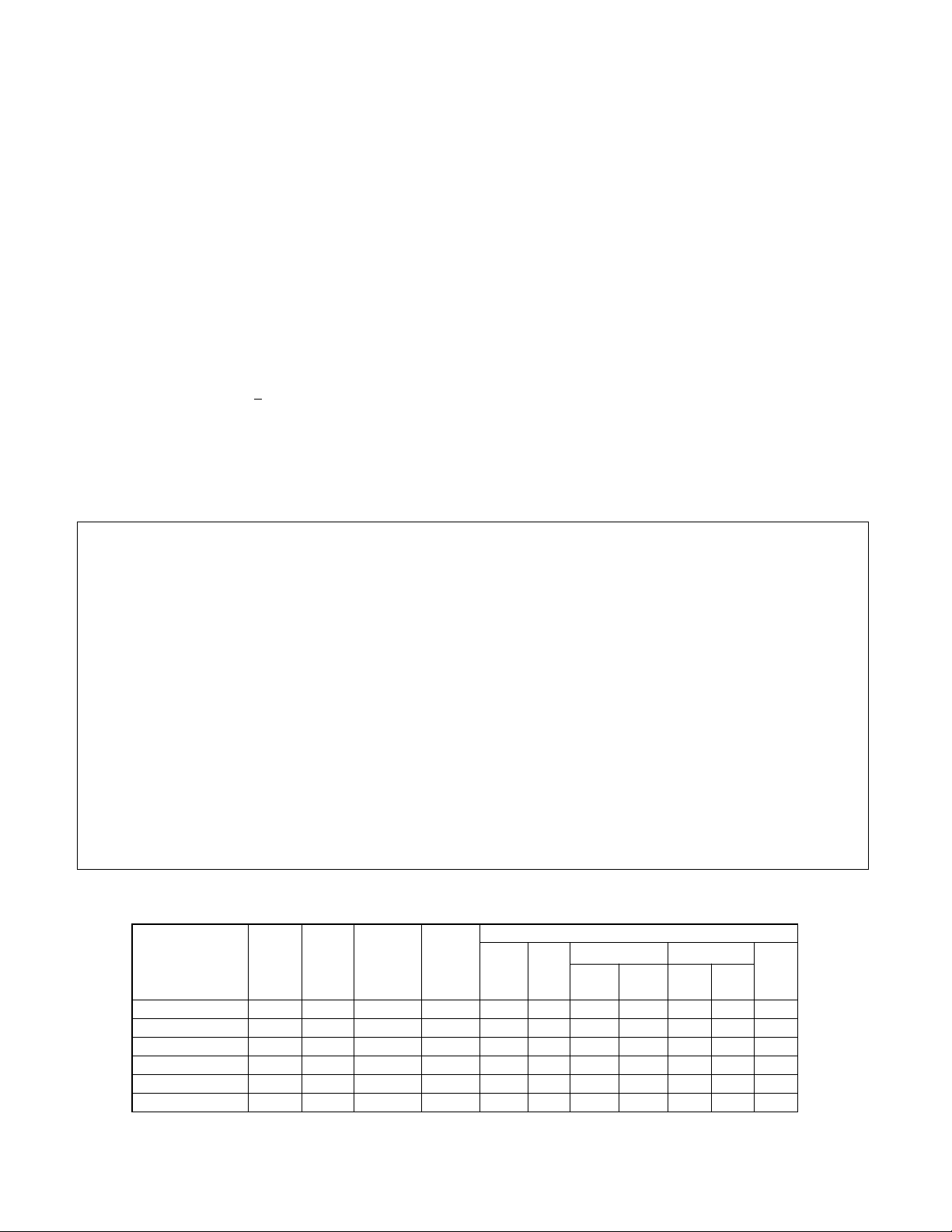
SPECIFICATIONS
MOTOR FRAMES - 182TC, 184TC, 213TC, 215TC, 254TC, 256TC.
ENCLOSURES - NEMA 2
(material: aluminum and cast iron)
DUTY - Rated for continuous duty.
VOLTAGES - All standard NEMA voltages and frequencies available.
Other voltages and frequencies are optional.
MOUNTING - Direct to NEMA “C” face, with one additional “C” face for
mounting of equipemnt to brake. Some standard motor shafts may
need modification, see Table 1.
Horizontal or vertical mounting with modifications.
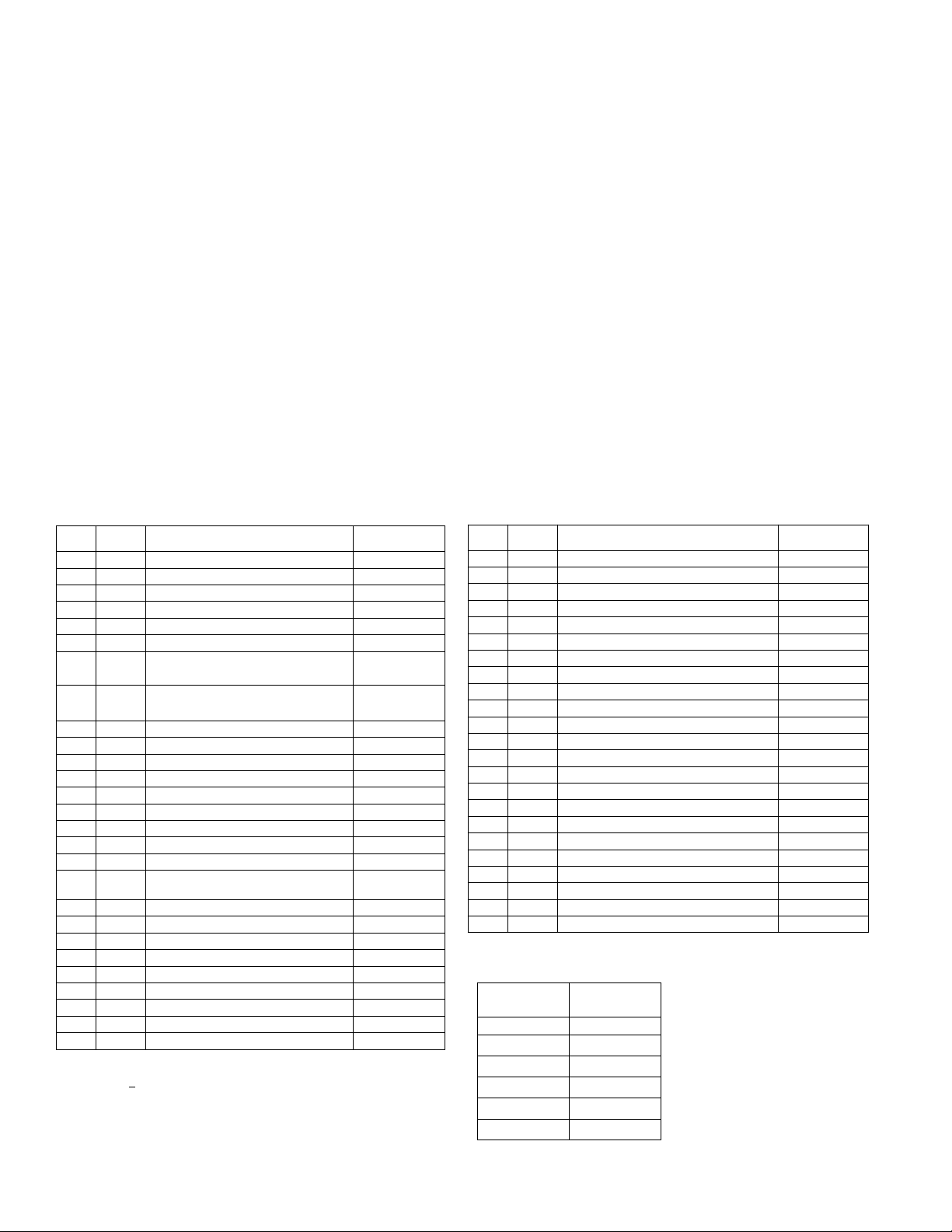
ORDERING INFORMATION
The following data should be furnished with your order for:
REPLACEMENT PARTS
Brake Model Number
Part Number from Tables
Part Description from Tables
Hub Bore & Keyway. Shaft Extension Diameter & Keyway.
For electrical parts specify voltage, phase, and frequency.
REPLACEMENT BRAKE
Model Number
Voltage, Phase & Frequency
Hub Bore & Keyway Dimensions. Shaft Extension Diameter & Keyway.
Mounting - Horizontal or Vertical. (If vertical, specify whether above or
below motor.
3

Table 2. Parts List
* Number of rotating discs is designated by model number;
example:6-72025-114 has two rotating discs.
Also see table 1 for number of rotating discs.
** Number of stationary discs is one less than the number of rotating discs.
4740 WEST ELECTRIC AVENUE, MILWAUKEE, WI 53219
PHONE 414/672-7830 FAX 414/672-5354 www. dingsbrakes.com
Model Number Torque
Spring P/N
6-71010-114 G070011-001
6-71015-114 G070012-001
6-72025-114 G070019-001
6-72035-114 G070012-001
6-73050-114 G070012-001
6-74075-114 G070012-001
Torque spring (Item 10) table
ITEM
NO.
PCS.
REQ'D DESCRIPTION PART NUMBER
1 1 Bracket (Specify brake model no.) L070203
2 2 Studs (Specify brake model no.) H070180
3 * Rotating friction disc H070103-008
4 ** Stationary disc K070485-001
5 1 Pressure plate assembly K070045-001
5a 2 Roll Pin, 5/32 x 9/16 lg. W005003-101
6 1 Magnet mounting plate assembly for 3-
phase magnets (Includes items 6a-6b) K070097
6 1 Magnet mounting plate assembly for 1-
phase magnets (Includes items 6a-6d) K070335
6a 2 Roll Pin, 5/32 x 1-1/8 lg. W005003-109
6b 6 Coils-three phase (See ordering info.) H020003
6b 2 Coils-single phase (See ordering info.) H070013
6c 2 Insulating washers, 1-phase coils G070029-001
6d 2 Shading coil (Single phase only) G070032-001
7 1 Housing (1-1/8 shaft) L070440-001
7 1 Housing (1-3/8 shaft) L070440-002
8 1 Shaft (Specify both diameter & keyway) Consult Factory
9 1 Hub (Specify both diameter & keyway) Consult Factory
10 2 Torque spring See torque spring
table
11 2Torque spring washer W004004-001
12 2 Manual release rod G070834-001
13 2 Manual release spring G060010-001
14 2 Manual release washer W004004-003C
15 As Req'd Manual release shims W004004-004C
16 2 Manual release stop screw G060029-001
17 2 Manual release lockwasher W004007-007
18 2 Manual release knob W035002-001
19 2 Roll Pin, 1/8 x 3/4 lg. W005003-073
Table 2. Parts List
ITEM
NO.
PCS.
REQ'D DESCRIPTION PART NUMBER
20 2 Manual release shaft G070833-001
21 2 Snap ring, Manual release W006008-005
22 2 Torque adjust nut W003001-022
23 2 Ball bearing, double seal (1-3/8 shaft) W009007-009
24 2 Bearing flange plate set, 72MS (1-3/8 shaft) W009006-005
25 6 Lockwasher, 3/8 W004006-008
26 6 3/8-16 X 7/8 bolt W001007-054
27 1 Wrap cover K070228-001
28 4 ESNA locknut 1/2-20 W003001-020
29 2 Hex jam nut 1/2-20 W003003-023
30 1 Cap plug W008003-001
31 2 Drive screws, nameplate W001012-048
32 1 Nameplate H050020-001
33 1 Pipe Plug, 1/2 NPT W010002-004
34 1 Key (Specify brake model no. & keyways) W007001
35 1 Foot mount bracket (1-1/8 shaft) L070446-001
35 1 Foot mount bracket (1-3/8 shaft) L070446-002
36 3 Snap ring, (1-1/8 shaft) W006003-004
36 3 Snap ring, (1-3/8 shaft) W006003-006
37 2 Ball bearing, double seal (1-1/8 shaft) W009007-006
38 2 Bearing flange plate set, 62MS (1-1/8 shaft) W009006-004
39 4 1/2-13 mounting bolt W001013-132
40 4 1/2 split lockwasher W004006-010
Figure 4
This manual suits for next models
6
Other Dynamics Industrial Equipment manuals
Popular Industrial Equipment manuals by other brands

Vertiv
Vertiv Liebert MCV Series Installer/user guide

ABB
ABB HT566023 Operation manual

Zimmer
Zimmer AEPN1100-00-A Installation and operating instructions

HYDAC FILTER SYSTEMS
HYDAC FILTER SYSTEMS LVU-CD-10 Operating and maintenance instructions

Spartan
Spartan TE200 Series user manual

ABB
ABB HT604702 Operation manual