Dynamics Dings 71010-EC6S User manual

4740 W. ELECTRIC AVE. • MILWAUKEE, WISCONSIN 53219 • 414/672-7830 • FAX 414/672-5354 • www.dingsbrakes.com
Read carefully before attempting to assemble, install, operate or maintain
the product described. Protect yourself and others by observing all safety
information. Failure to comply with instructions could result in personal injury
and/or property damage! Retain instructions for future reference.
DESCRIPTION
These magnetic disc brakes mount directly onto NEMA182TC, 213TC, and
256TC frame motors, on the end opposite the drive shaft. The brake is direct
acting, electro-magnetically released, and spring set. It uses rotating friction and
stationary disc contact to supply positive braking action. It retains quick release
and setting capabilities at all times.
WARNING: Do not install or use these brakes in an explosive atmosphere.
WARNING: Brake performance and features must be carefully matched to the requirements of the
application. Consideration must be given to torque requirements, especially where an overhauling condition
exists, as well as thermal capacity, ambient temperature, atmospheric explosion hazards, type of enclosure
and any other unusual conditions. Improper selection and installation of a brake and/or lack of maintenance
may cause brake failure which could result in damage to property and/or injury to personnel. If injury to
personnel could be caused by brake failure, additional means must be provided to insure safety of personnel.
UNPACKING
When unpacking the brake, inspect it carefully for damage that may have occurred during transit. Do not activate the
manual release without the hub inserted in the discs as doing so may result in loss of disc spline alignment.
GENERAL SAFETY INFORMATION
NOTE: These brakes are not intended for accurate positioning applications. They are designed for applications that
require rapid stopping and holding power, such as on conveyors, door openers, etc.
1. For applications with high inertia-type loads or rapid cycling, the thermal capacity of the brake must be considered.
2. Observe all local electrical and safety codes, as well as the National Electrical Code (NEC) & the Occupational
Safety and Health Act (OSHA).
3. Brake motors & brake gearmotors must be securely & adequately grounded. This can be accomplished by wiring
with a grounded metal-clad raceway system, by using a separate ground wire connected to the bare metal of the
motor frame, or other suitable means. Refer to NEC Article 250 (Grounding) for additional information. All wiring
should be done by a qualified electrician.
4. Always disconnect power before working on or near a brake motor, a brake gearmotor, or its connected load. If the
power disconnect point is out of sight, lock it in the open position and tag it to prevent unexpected application of
power.
5. When working on the brake, be sure the load is completely removed, secured or blocked to prevent injury or
property damage.
6. Provide guarding for all moving parts.
7. Be careful when touching the exterior of an operating motor, gearmotor or brake. It may be hot enough to cause
injury or to be painful. This condition is normal for modern motors, which operate at higher temperatures when
running at rated load & voltage.
8. Protect all electrical lead wires & power cables against contact with sharp objects or moving parts.
9. Do not kink electrical lead wires & power cables, and never allow them to touch oil, grease, hot surfaces, or chemicals.
70 Series 8700 End Mount
Three Phase Brake Instructions
IP56 (NEMA 4) Housing
Bulletin No. BK4773S-3 (6/2017)
R
t
i
a
D
T
2
a
s
a

4740 W. ELECTRIC AVE. • MILWAUKEE, WISCONSIN 53219 • 414/672-7830 • FAX 414/672-5354 • www.dingsbrakes.com
BK4773S-3 (6/2017) 2
Figure 1 - Brake Outline
RECOMMENDED TOOLS AND HARDWARE
NOTE: The following tools and hardware are required for installing the brake onto a motor or mounting bracket. Use
proper torque when required to ensure fasteners do not loosen during operation.
• 3/4 INCH HEX WRENCH OR RATCHET/SOCKET
• 3/16 HEX BIT SOCKET (OR KEY)
• TORQUE WRENCH
• QUANTITY (4), 1/2 diameter SHCS, MINIMUM 1” LONG (see installation note #5 below)
• 3/8 BALL END HEX BIT SOCKET (KEY OR T-HANDLE)
INSTALLATION
(See Figures 1, & 2, Table 1)
1. Remove hub (99) from brake and position on motor shaft with key according to dimension “N” per figure 1.
Stamped part number on hub should face away from motor. Tighten hub set screws with 18 lb.ft. torque.
2. Remove temporary cover nut and cover (67). Set cover aside. Discard temporary nut.
3. If brake is supplied with a mounting face gasket (91), place gasket onto the brake mounting face.
4. Place brake on motor, guiding discs on hub. Use caution not to pinch gasket. For horizontal mounted brakes, the
drain plug should be pointed down.
5. Bolt brake to motor “C” face with four socket head cap screws. See Figure 1 to help in determining proper bolt
length. Final bolt thread pitch, length and mounting torque is dependent on the material and depth of the threaded
holes in the mounting face.
6. Connect coil leads per appropriate wiring diagram in Figure 1 and replace cover (67).
7. Use provided sealing washers (70) and nylon locking nuts (71) to secure cover (67).

4740 W. ELECTRIC AVE. • MILWAUKEE, WISCONSIN 53219 • 414/672-7830 • FAX 414/672-5354 • www.dingsbrakes.com
BK4773S-3 (6/2017) 3
MAINTENANCE
CAUTION: Before attempting to service or remove any components, make certain that the power is disconnected and
that the load is completely removed, secured or blocked to prevent injury or property damage.
Wear Adjustment
CAUTION: Load to be removed or blocked. Brake may be inoperative during this procedure.
Before air gap “D” reaches .100”, adjustment is required. Any delay in adjusting
the magnet air gap will result in eventual loss of torque. Refer to Fig. 1, 2 & 3.
1. To adjust, remove cover locknuts/seals (70 & 71) and cover (67) to expose
wear adjusting screws on item (32) and expose magnet air gap “D”.
2. Measure air gap “D” using 3/8” to 1/2” wide feeler gauge.
Measure at center of magnet.)
3. Turn two adjusting screws on item(32) until air gap “D” measures:
.035/.045 for 1 disc models
.035/.045 for 2 disc models
.045/.055 for 3 disc models
.055/.065 for 4 disc models
Air gap should be the same on both sides.
Torque Adjustment
Caution: Load to be removed or blocked. Brake may be inoperative during this procedure.
The magnetic disc brake is factory set for rated static torque. The brake can be adjusted to reduce torque which increases
stopping time. Do not attempt to adjust brake for higher torque, as this will cause premature coil burnout. (Refer to Fig. 1 & 2)
1. To adjust, remove cover locknuts/seals (70 & 71) and cover (67) to expose torque locknuts (44), which are above torque
springs (42).
2. To increase stopping time and reduce torque, turn two locknuts (44) counterclockwise, increasing spring length.
Each full turn reduces torque 7% to 10% depending upon the model.
Figure 2 - Exploded View of Brake
Figure 3 - Air Gap

4740 W. ELECTRIC AVE. • MILWAUKEE, WISCONSIN 53219 • 414/672-7830 • FAX 414/672-5354 • www.dingsbrakes.com
BK4773S-3 (6/2017) 4
Friction Disc Replacement
Caution: Load to be removed or blocked. Brake will be inoperative during this procedure.
If brake model number has a prefix VO, VU, or VA for vertical mounting, see page 8. When rotating friction disc (25) wears to
one-half of the original thickness, or 0.156”, replace disc:
1. Removing electromagnet assembly
Disconnect power.
2. Remove cover locknuts/seals (70 & 71) and cover (67).
3. Remove electromagnet assembly (32 & 50A) by removing nuts and washers (61, 60, & 59) from the magnet assembly
(50A). Remove magnet assembly (50A). Remove all nuts, washers, and springs (44, 43, & 42) from pressure plate (32).
Remove pressure plate (32) by rotating counter-clockwise to remove torque spring bolts (28) from slots in brake bracket
(1).
4. Replacing the friction disc
Remove worn rotating discs (25) and stationary discs (26). Replace worn discs and install new discs in the same order.
5. Re-assembly of electromagnet assembly (15) Refer to Fig. 1 & 2. Reinstall pressure plate (32) by rotating clockwise
to engage both torque spring bolts (28) into slots in brake bracket (1). Replace all nuts, washers, and springs (42, 43, &
44). Nut (44) on the pivot post (17) should be adjusted, so the distance from the bottom of the pressure plate (32) to
the top of the brake bracket (1) is 7/16”. Reinstall magnet assembly (50A) and install nuts and washers (59, 60, & 61).
Nut (61) should be torqued to 20 lb-ft.
6. Readjust magnet air gap “D” as described under “Wear Adjustment”.
7. Reset spring height according to brake model number in Fig.1 from the top of the spring (42) to the bottom of the
pressure plate (32).
8. Energize coil. Magnet should be quiet; if not, refer to “Pivot Stud Adjustment”.
9. Check manual release operation before completing installation. Adjust per “Manual Release Adjustment” if required.
10. Completing installation
Replace cover (67) and cover locknuts/seals (70 & 71). Tighten nut (71) to 30 lb-in. Reconnect power.
Magnet Assembly Replacement
Caution: Load to be removed or blocked. Brake will be inoperative during this procedure.
1. Disconnect power supply.
2. Remove cover locknuts/seals (70 & 71) and cover (67).
3. Remove nuts and washers (59, 60, & 61) from magnet assembly (50A) & remove assembly.
4. Replace with new magnet assembly (50A) and install nuts and washers (59, 60, & 61). Nut (61) should be torqued to
20 lb-ft.
5. Place coil lead wires around mounting bracket (1) to the same side as the wire outlet position or internal wire outlet.
Connect coil lead wires per Fig. 1.
6. Set air gap “D” as described under “Wear Adjustment”.
7. Energize coil. Magnet should be quiet; if not, refer to “Pivot Stud Adjustment”.
8. Check manual release. If it does not operate properly, adjust as outlined under “Manual Release Adjustment”.
9. Replace cover (67) and cover locknuts/seals (70 & 71). Tighten nut (71) to 30 lb-in. Reconnect power.
Pressure Plate Replacement
CAUTION: Load to be removed or blocked. Brake will be inoperative during this procedure.
If you replace the magnet assembly, it may be necessary to replace the pressure plate (32). If it is badly deformed, it will be
difficult to make the magnet quiet.
1. To replace, remove electromagnet assembly (32 & 50A) from brake. See “Friction Disc Replacement Steps 1-3”.
2. Replace with new pressure plate (32) and reassemble per “Friction Disc Replacement Steps 5-10”.
Pivot Stud Adjustment
CAUTION: Load to be removed or blocked. Brake will be inoperative during this procedure.
This adjustment is made at the factory and may be required when replacing the magnet assembly (50A) or the pressure plate
(32). The purpose is to regulate the height of the pressure plate (32) so that when the magnet (50A) is energized, the pressure
plate (32) is parallel with it. This is required so that the magnet will be quiet.
NOTE: Cover (67) must be removed to make this adjustment.
1. To adjust: Rotate nut (44) with washer (43) on pivot post (17) until the height from the bottom of the pressure plate (32) to
the top of the brake bracket (1) is near 7/16”.
2. Energize the magnet and turn nut (44) counterclockwise slowly until the magnet becomes noisy. Turn nut (44) clockwise
until the magnet becomes quiet. Hold nut in this position and turn magnet on and off to make sure the magnet does not
become noisy.
3. Operate the manual release. If the release does not operate properly, see “Manual Release Adjustment”.

4740 W. ELECTRIC AVE. • MILWAUKEE, WISCONSIN 53219 • 414/672-7830 • FAX 414/672-5354 • www.dingsbrakes.com
BK4773S-3 (6/2017) 5
Manual Release Adjustment
CAUTION: Load to be removed or blocked. Brake will be inoperative during this procedure.
The manual release (7) may require adjustment after replacing the electromagnet assembly (50A & 32), magnet (50A), or
pressure plate (32). It also may be required if adjustments are made on the pivot post nut (44).
The release is working properly if:
a) You turn release (7) clockwise to stop and the brake is released;
b) The release returns to its normal position automatically when power is applied to the magnet.
NOTE: Cover (67) must be removed to make this adjustment.
1. To adjust: Set air gap “D” as described under “Wear Adjustment”.
2. If the brake does not release, turn the adjusting screw above the manual release cam (12) on the pressure plate (32)
counterclockwise and try again.
3. If the manual release (7) does not return to its normal position automatically, turn the adjusting screw above the manual
release cam (12) on the pressure plate (32) clockwise and try again.
NOTE: You may have to repeat Steps 2 or 3 to get the release to operate properly. It is important that the manual release
returns to its normal position automatically when power is applied to the magnet.
Manual Release Assembly
Refer to Fig. 2
1. Place the end of the manual release shaft (7) with the threaded hole through the hole in the bracket (1).
2. Slide the return spring (11) over the shaft. The straight leg of spring should bottom out on the bracket and the bent
piece should point towards the brake hub (99) or motor shaft.
3. The manual release cam (12) should be placed on the Double-D end of the shaft with the bent part of the return spring
(11) resting just above the Double-D portion of the manual release cam (12).
4. Install manual release screw (13) to hold manual release cam (12) to the manual release (7).
5. Adjust release. See “Manual Release Adjustment”.
Figure 2 - Exploded View of Brake

4740 W. ELECTRIC AVE. • MILWAUKEE, WISCONSIN 53219 • 414/672-7830 • FAX 414/672-5354 • www.dingsbrakes.com
BK4773S-3 (6/2017) 6
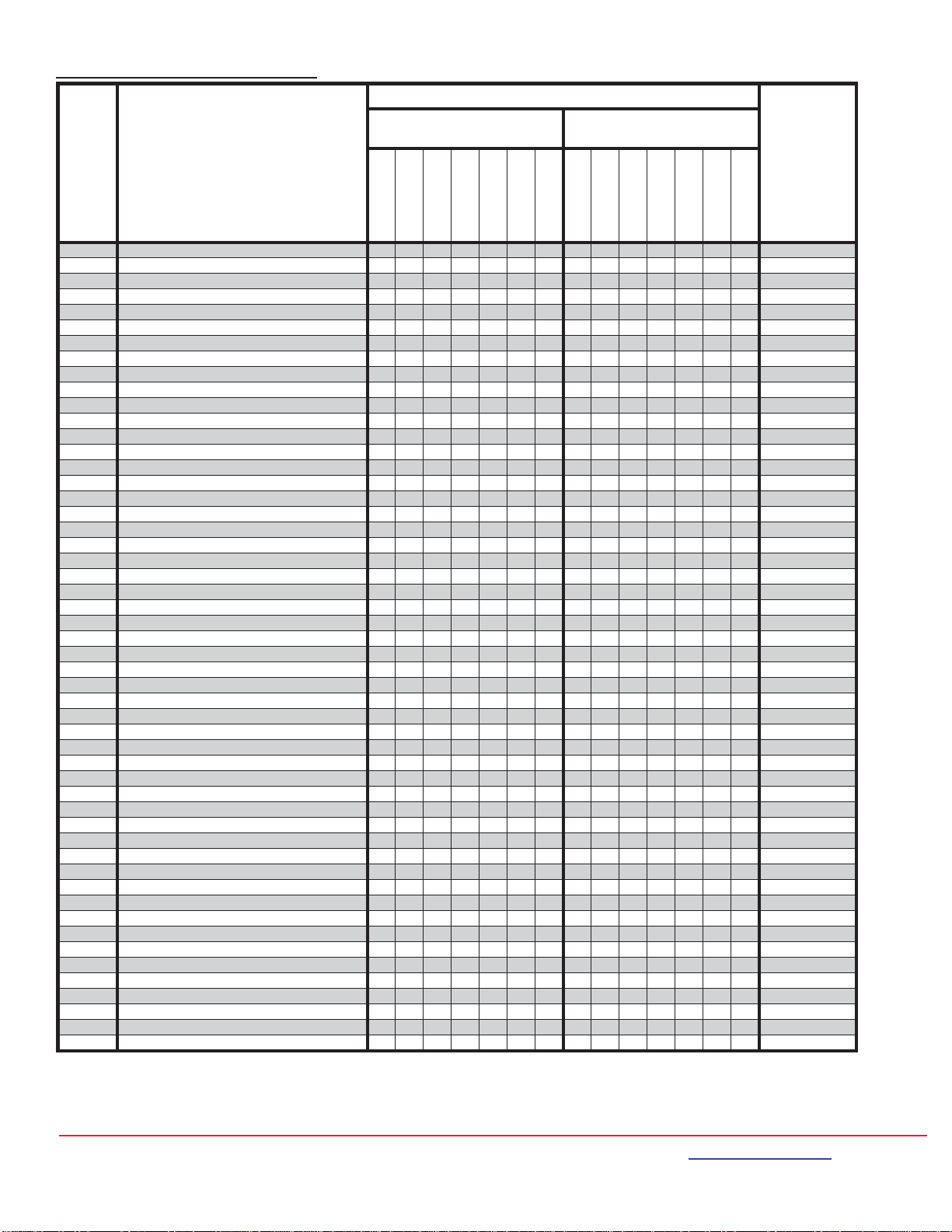
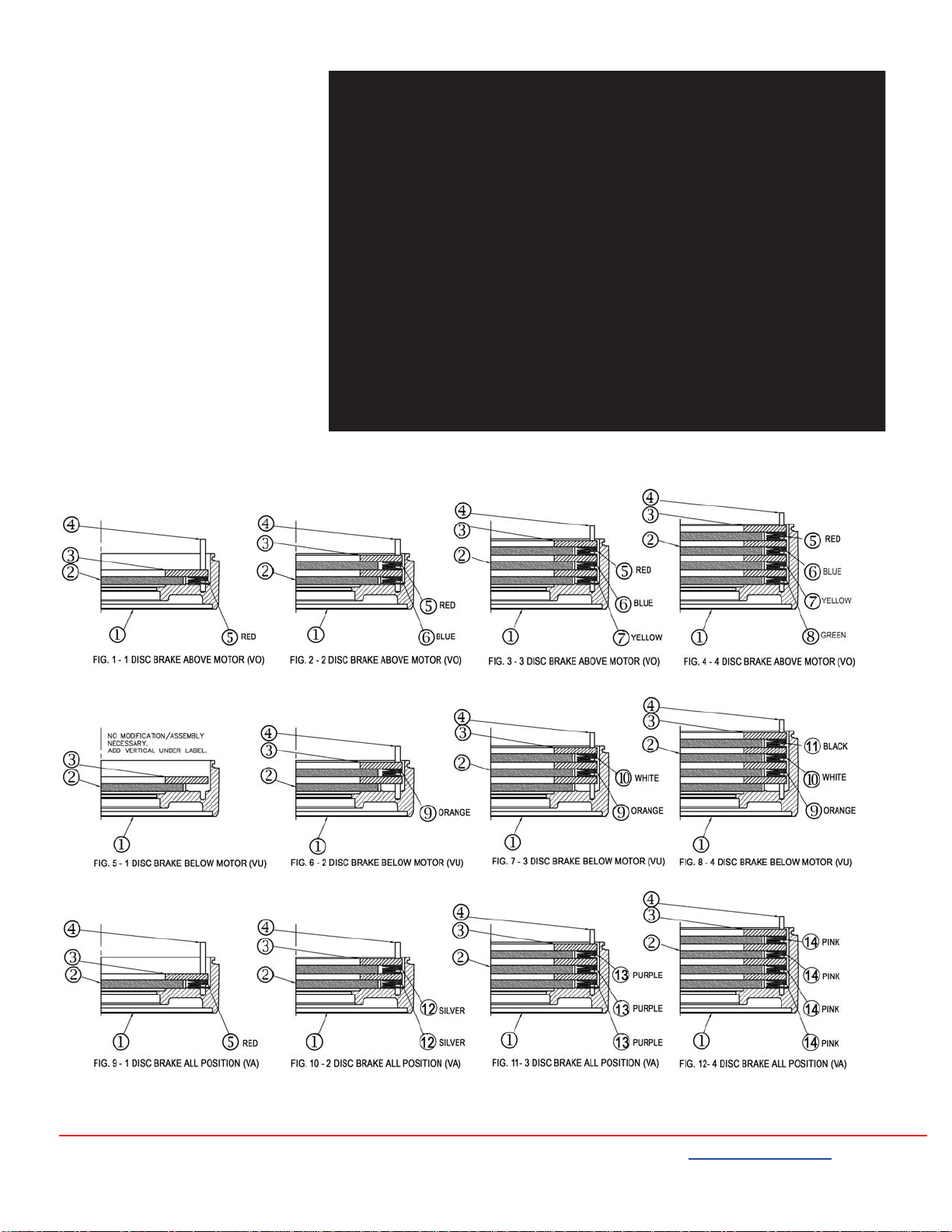
REPLACEMENT PARTS LIST (See Figure 2)
ITEM
NO. DESCRIPTION
MODEL
PART NO.
IP56 (NEMA 4) Endmount
without seal IP56 (NEMA 4) Endmount
with seal
71010-EC6S
71015-EC6S
71025-EC6S
72035-EC6S
72050-EC6S
73075-EC6S
74105-EC6S
71010-SC6S
71015-SC6S
71025-SC6S
72035-SC6S
72050-SC6S
73075-SC6S
74105-SC6S
1 Bracket assembly, 1&2 disc 1111 K070579-XXX
1 Bracket assembly, 1&2 disc with hub seal 1111 K070579-XXX
1 Bracket assembly, 3 disc 1 K070580-XXX
1 Bracket assembly, 3 disc with hub seal 1 K070580-XXX
1 Bracket assembly, 4 disc 1 1 K070581-XXX
1 Bracket assembly, 4 disc with hub seal 1 1 K070581-XXX
7 Handle, manual release 11111111111111H070422-002
11 Spring, return manual release 11111111111111G070846-001
12 Cam, manual release 11111111111111H070393-001
13 Screw, retaining, cam 11111111111111W001045-043
17 Post, pivot 11111111111111W002005-168
19 Stud post, magnet assembly/cover 22222222222222H070395-001
25 Disc, rotating friction 11223441122344H070394-001
26 Disc, stationary 11223441122344K070560-001
27 Spring, pivot 11111111111111G070847-001
28 Bolt, torque spring 22222222222222W001007-069
32 Pressure plate assembly, three phase 11111111111111H070423-001
37 Bushing, flanged 33333333333333W013007-061
42 Spring, torque, silver 2 2 G070848-001
42 Spring, torque, gold 222222 222222 G070849-001
43 Washer, flat 33333333333333W004002-008
44 Nut, adjustment 33333333333333W003013-005
46 Washer, magnet assembly base 22222222222222W004004-018
50A Magnet Assembly, three phase 11111111111111H070402-XXX
50 Magnet frame, three phase 11111111111111K070567-001
51 Coil, magnet, three phase 33333333333333H020003-XXX
54 Clamp, cable 11111111111111W021008-005
55 Screw, cable clamp 11111111111111W001038-143
59 Washer, shock absorber 22222222222222G070850-001
60 Washer, capture 22222222222222W004004-017
61 Nut, nylock magnet assembly 22222222222222W003001-020
65 O-ring, bracket/cover 11111111111111W006001-036
67 Cover, cast iron 11111111111111K070554-001
70 Sealing washer 22222222222222W011002-010
71 Nut, cover 22222222222222W003001-020
84 Nameplate, metal 11111111111111K070574-001
85 Drive screw 22222222222222W001012-048
86 Release label 11111111111111G070852-001
87 Capplug, 1/2 NPT 1111111W008003-001
87 Pipe plug, 1/2 1111111 W010002-004
88 Pipe plug, 1/8 11111111111111W010002-004
91 Bracket gasket 1111111 K070250-005
99 Hub assembly 1 disc 1 1 1 H070409-XXX
99 Hub assembly 2 disc (35lb-ft) 1 H070412-XXX
Hub assembly 2 disc (50lb-ft) 1 H070414-XXX
99 Hub assembly 3 disc 1 H070417-XXX
99 Hub assembly 4 disc 1 H070420-XXX
99 Hub assembly 1 disc w/seal 1 1 1 H070410-XXX
99 Hub assembly 2 disc (35lb-ft) w/seal 1 H070413-XXX
Hub assembly 2 disc (50lb-ft) w/seal 1 H070415-XXX
99 Hub assembly 3 disc w/seal 1 H070418-XXX
99 Hub assembly 4 disc w/seal 1 H070421-XXX
XXX - Part number depends upon brake model number
Table 1. Parts List

4740 W. ELECTRIC AVE. • MILWAUKEE, WISCONSIN 53219 • 414/672-7830 • FAX 414/672-5354 • www.dingsbrakes.com
BK4773S-3 (6/2017) 7
EXPLODED VIEW
(See Table 1)
Figure 2 - Exploded View of Brake

4740 W. ELECTRIC AVE. • MILWAUKEE, WISCONSIN 53219 • 414/672-7830 • FAX 414/672-5354 • www.dingsbrakes.com
BK4773S-3 (6/2017) 8
VERTICAL MOUNTING
Installation and Adjustment
Installation and adjustment of the
vertically mounted brake is the same as
on the standard model.
Friction Disc Replacement
When replacing friction discs, follow
procedure outlined on page 3 with this
addition:
Care must be taken to insure proper
insertion of disc separating springs.
Springs are color coded for easy
identification, and reference is made to
spring color (See table to the right &
diagram below). Since the installation
order of the disc springs is dependent on
brake mounting position (above or below
motor), it is important to consult the
correct diagram for spring location.
This manual suits for next models
14
Table of contents
Other Dynamics Industrial Equipment manuals
Popular Industrial Equipment manuals by other brands

Ormazabal
Ormazabal velatia cpg.0 General instructions

Siemens
Siemens CP 5624 operating instructions

GREER Company
GREER Company MicroGuard RCI 510 troubleshooting manual

XtraVac
XtraVac CM1440B Operations & parts manual

Zimmer
Zimmer GG4000 Series Installation and operating instructions

Full Spectrum Laser
Full Spectrum Laser MUSE MOPA user manual